Table of Contents
Advertisement
SERVICE MANUAL
Ver. 1.0 2016.12
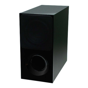
• SA-WCT800 is the active subwoofer in HT-CT800.
• All of the units included in the HT-CT800 (SA-WCT800/
SA-CT800/Remote control) are required to confi rming
operation of SA-WCT800. Check in advance that you
have all of the units.
• For the TEST MODE for this unit, refer to the service manual of HT-CT800.
SPECIFICATIONS
POWER OUTPUT (reference)
130 W (at 4 ohms, 80 Hz)
Speaker system
Subwoofer speaker system, Bass
reflex
Speaker
160 mm (6 3/8 in) cone type
Power requirements
120 V AC, 60 Hz (US, CND)
220 V - 240 V AC, 50 Hz/60 Hz
(AEP, UK)
Power consumption
On: 25 W
Standby mode: 0.5 W or less
Dimensions (approx.) (w/h/d)
190 mm × 382 mm × 386 mm (7 1/2 in x
15 1/8 in x 15 1/4 in) (not including
projection portion)
Mass (approx.)
7.8 kg (17 lb 3 1/8 oz)
Wireless receiver section
Communication system
Wireless Sound Specification version
2.0
Frequency band
2.4 GHz (2.4000 GHz - 2.4835 GHz)
Modulation method
Pi/4 DQPSK
Design and specifications are subject to
change without notice.
9-896-352-01
2016L33-1
Sony Video & Sound Products Inc.
©
2016.12
SA-WCT800
responsible for the operation of this device
Copyrights and Trademarks
or its compliance with safety and
regulatory standards. Please note that the
This system incorporates Dolby* Digital
use of this accessory with iPod or iPhone
and the DTS** Digital Surround System.
may affect wireless performance.
* Manufactured under license from Dolby
"BRAVIA" logo is a trademark of Sony
Laboratories.
Corporation.
Dolby and the double-D symbol are
trademarks of Dolby Laboratories.
"ClearAudio+" is a trademark of Sony
**For DTS patents, see http://
Corporation.
patents.dts.com. Manufactured under
license from DTS Licensing Limited. DTS,
WALKMAN® and WALKMAN® logo are
DTS-HD, the Symbol, & DTS and the
registered trademarks of Sony
Symbol together are registered
Corporation.
trademarks of DTS, Inc. © DTS, Inc. All
Rights Reserved.
"PlayStation" is a registered trademark or
trademark of Sony Interactive
®
The BLUETOOTH
word mark and logos are
Entertainment Inc.
registered trademarks owned by Bluetooth
SIG, Inc. and any use of such marks by Sony
MPEG Layer-3 audio coding technology
Corporation is under license. Other
and patents licensed from Fraunhofer IIS
trademarks and trade names are those of
and Thomson.
their respective owners.
Windows Media is either a registered
This system incorporates High-Definition
trademark or trademark of Microsoft
Multimedia Interface (HDMI™) technology.
Corporation in the United States and/or
The terms HDMI and HDMI High-Definition
other countries.
Multimedia Interface, and the HDMI Logo
This product is protected by certain
are trademarks or registered trademarks of
intellectual property rights of Microsoft
HDMI Licensing, LLC in the United States
Corporation. Use or distribution of such
and other countries.
technology outside of this product is
prohibited without a license from Microsoft
The N Mark is a trademark or registered
or an authorized Microsoft subsidiary.
trademark of NFC Forum, Inc. in the United
States and in other countries.
Opera® Devices SDK from Opera Software
ASA. Copyright 1995-2016 Opera Software
Android, Google Play and Chromecast are
ASA. All rights reserved.
trademarks of Google Inc.
Apple, the Apple logo, iPhone, iPod, iPod
touch, and Retina are trademarks of Apple
Inc., registered in the U.S. and other
countries. App Store is a service mark of
Apple Inc.
Wi-Fi®, Wi-Fi Protected Access® and Wi-Fi
Alliance® are registered trademarks of Wi-
"Made for iPod," and "Made for iPhone"
Fi Alliance.
mean that an electronic accessory has
been designed to connect specifically to
Wi-Fi CERTIFIED™, WPA™, WPA2™ and Wi-
iPod or iPhone, respectively, and has been
Fi Protected Setup™ are trademarks of Wi-
certified by the developer to meet Apple
Fi Alliance.
performance standards. Apple is not
US Model
Canadian Model
AEP Model
UK Model
LDAC™ and LDAC logo are trademarks of
or certification marks of the Digital Living
Sony Corporation.
Network Alliance.
LDAC is an audio coding technology
developed by Sony that enables the
"TRILUMINOS" and "TRILUMINOS" logo are
transmission of High-Resolution (Hi-Res)
a registered trademark of Sony
Audio content, even over a Bluetooth
Corporation.
connection. Unlike other Bluetooth
compatible coding technologies such as
This product incorporates Spotify software
SBC, it operates without any down-
which is subject to 3rd party licenses found
conversion of the Hi-Res Audio content*,
here*:
and allows approximately three times
https://developer.spotify.com/esdk-
more data** than those other technologies
third-party-licenses/
to be transmitted over a Bluetooth wireless
network with unprecedented sound
Spotify and Spotify logos are trademarks of
quality, by means of efficient coding and
the Spotify Group.*
optimized packetization.
* Depending on the country and region,
* excluding DSD format contents
this function may not be available.
**in comparison with SBC (Subband
All other trademarks are trademarks of
Coding) when the bitrate of 990 kbps
their respective owners.
(96/48 kHz) or 909 kbps (88.2/44.1 kHz) is
selected
This product contains software that is
subject to the GNU General Public License
("GPL") or GNU Lesser General Public
License ("LGPL"). These establish that
customers have the right to acquire,
modify, and redistribute the source code of
said software in accordance with the terms
of the GPL or the LGPL.
For details of the GPL, LGPL and other
software licenses, please refer to [Software
License Information] in [System Settings] of
the [Setup] menu on the product.
The source code for the software used in
this product is subject to the GPL and LGPL,
and is available on the Web. To download,
please access the following:
URL:
http://oss.sony.net/Products/Linux
Please note that Sony cannot answer or
respond to any inquiries regarding the
content of this source code.
"DSEE" is a trademark of Sony Corporation.
DLNA™, the DLNA Logo and DLNA
CERTIFIED™ are trademarks, service marks,
ACTIVE SUBWOOFER
Advertisement
Table of Contents

Related Manuals for Sony SA-WCT800


Summary of Contents for Sony SA-WCT800
- Page 1 AEP Model UK Model • SA-WCT800 is the active subwoofer in HT-CT800. • All of the units included in the HT-CT800 (SA-WCT800/ SA-CT800/Remote control) are required to confi rming operation of SA-WCT800. Check in advance that you have all of the units.
-
Page 2: Table Of Contents
LES DIAGRAMMES SCHÉMATIQUES ET LA LISTE DES PIÈCES SONT CRITIQUES POUR LA SÉCURITÉ DE FONC- TIONNEMENT. NE REMPLACER CES COMPOSANTS QUE PAR DES PIÈCES SONY DONT LES NUMÉROS SONT DON- NÉS DANS CE MANUEL OU DANS LES SUPPLÉMENTS PUBLIÉS PAR SONY. -
Page 3: Servicing Notes
All of the units included in the HT-CT800 (SA-WCT800/SA- Destination CT800/Remote control) are required to confi rming operation of Destination Part No. code SA-WCT800. Check in advance that you have all of the units. US, CND models 4-684-829-0[] (UC2) AEP model 4-684-831-0[]... - Page 4 SA-WCT800 WIRELESS CONNECTION (LINK) WORK OF BAR SPEAK- NOTE OF REPLACING THE ELECTRICAL PARTS ON ER AND SUBWOOFER EACH BOARDS FOR REPAIRING When the parts below is replaced, the wireless connection (LINK) Among mounted electrical parts on each boards, only parts that of the Bar speaker and Subwoofer will be disconnected.
- Page 5 SA-WCT800 BOND FIXED POSITION OF ELECTRICAL PARTS When the parts that fi xed on the board by the bond have been removed, fi x the parts by using the bond (ADHESIVE (SC608Z2)) in the mounting to the board. (Refer to the fi gure below) ]: Bond application portion –...
-
Page 6: Disassembly
SA-WCT800 SECTION 2 DISASSEMBLY • This set can be disassembled in the order shown below. 2-1. DISASSEMBLY FLOW 2-2. AMP BLOCK 2-8. SUB LED BOARD, FRONT PANEL ASSY (Page 6) (Page 11) 2-9. LOUDSPEAKER (SP1) 2-3. SUB-MAIN BOARD (Page 12) (Page 7) 2-4. -
Page 7: Sub-Main Board
SA-WCT800 2-3. SUB-MAIN BOARD Note 1: When the SUB-MAIN board is replaced, refer to “WIRELESS CONNECTION (LINK) WORK OF BAR SPEAKER AND SUBWOOFER” and “SPREADING OF COMPOUND” on page 4. top side Note 3: Fix the cable so that it does not come in contact with the heat sink. -
Page 8: Power Cord (Ac1)
SA-WCT800 2-4. POWER CORD (AC1) lock side cord bushing (FBS001) power cord (AC1) 95 +5, -0 mm top side to SUB-POWER board 5 cord bushing (FBS001) rear side 4 Unlock. Note: When installing the power cord block, check the direction and position of claw of the cord bushing (FBS001) and install correctly. -
Page 9: Sub-Power Board
SA-WCT800 2-5. SUB-POWER BOARD top side 3 connector (CN7201) Note 1: Before connect this connector, rear side refer to “CAPACITOR ELECTRICAL DISCHARGE PROCESSING” on page 3. 6 SUB-POWER board Note 2: When installing the SUB-POWER board, align the two ribs and two holes. -
Page 10: Rf Modulator (Rf1)
SA-WCT800 2-6. RF MODULATOR (RF1) Note: When the RF modulator (RF1) is replaced, refer to “WIRELESS CONNECTION (LINK) WORK OF BAR SPEAKER AND SUBWOOFER” on page 4. top side 5 Remove the RF modulator block RF modulator in the direction of the arrow. -
Page 11: Sub Led Board, Front Panel Assy
SA-WCT800 2-8. SUB LED BOARD, FRONT PANEL ASSY 1 Insert a flat-head screwdriver into the two slits on the bottom of the unit, and open a gap between the front 2 Insert the jig into the space and slowly panel block and speaker cabinet. -
Page 12: Loudspeaker (Sp1)
SA-WCT800 2-9. LOUDSPEAKER (SP1) Note 1: When installing the loudspeaker (SP1), make the position of terminals as shown in the figure below. 1 six screws top side (BVTP4 terminals position 4 loudspeaker (SP1) 2 Lift up the loudspeaker block in the direction of the arrow. -
Page 13: Troubleshooting
SA-WCT800 SECTION 3 TROUBLESHOOTING 1. ON/STANDBY indicator fl ashes in red (PROTECT) Note: When the volume level is “0”, power of amplifi er block is turned off, and amplifi er protect diagnosis is not performed. Set the volume level than “1”. - Page 14 SA-WCT800 2. ON/STANDBY indicator does not light up (Power is not turned on) ON/STANDBY indicator does not light up. (Power is not turned on) Replace the damaged fuse or fusible resistor on the SUB-POWER board. The voltage of the following is about...
- Page 15 SA-WCT800 3. The sound is not outputted The sound is not outputted. There is no problem of flexible flat cable (FFC1) contact between RF modulator Replace the flexible flat cable (RF1) and connector (CN702) on the (FFC1). SUB-MAIN board. Check the mounted state of area surrounding IC7400 on the SUB-MAIN board do not short- The waveform of the following is normal.
- Page 16 SA-WCT800 MEMO...
-
Page 17: Diagrams
SA-WCT800 SECTION 4 DIAGRAMS THIS NOTE IS COMMON FOR PRINTED WIRING BOARDS AND SCHEMATIC DIAGRAMS. • Waveforms (In addition to this, the necessary note is printed in each block.) – SUB-MAIN Board – For Printed Wiring Boards. For Schematic Diagrams. -
Page 18: Schematic Diagram - Sub-Main Board (1/2)
SA-WCT800 4-1. SCHEMATIC DIAGRAM - SUB-MAIN Board (1/2) - • See page 17 for Waveforms. • See page 24 for IC Block Diagrams. • See page 26 for IC Pin Function Description. SUB-MAIN BOARD (1/2) CN7400 CL7471 3.3V CL7472 CL7473... -
Page 19: Schematic Diagram - Sub-Main Board (2/2)
SA-WCT800 4-2. SCHEMATIC DIAGRAM - SUB-MAIN Board (2/2) - • See page 17 for Waveforms. • See page 24 for IC Block Diagrams. SUB-MAIN BOARD (2/2) CN702 JL7490 DC_DET JL7513 CLIP JL7486 R7522 SL7200 JL7505 DRIVER_SD DOUT_RX Q7200 JL7497 R7526... -
Page 20: Printed Wiring Board - Sub-Main Board
SA-WCT800 4-3. PRINTED WIRING BOARD - SUB-MAIN Board - • : Uses unleaded solder. SUB-MAIN BOARD SUB-MAIN BOARD (COMPONENT SIDE) (CONDUCTOR SIDE) (HEAT SINK) CL7478 C7240 CL7471 SL7200 CL7479 JL7203 (CHASSIS) C7123 CN7407 Q7200 CL7473 FFC1 CL7474 (CHASSIS) R7241 R7402... -
Page 21: Printed Wiring Board - Sub-Key Board
SA-WCT800 4-4. PRINTED WIRING BOARD - SUB-KEY Board - 4-6. PRINTED WIRING BOARD - SUB LED Board - • : Uses unleaded solder. • : Uses unleaded solder. SUB-KEY BOARD SUB LED BOARD (SIDE A) (SIDE A) S7011 S7010, 7011... -
Page 22: Schematic Diagram - Sub-Power Board
SA-WCT800 4-8. SCHEMATIC DIAGRAM - SUB-POWER Board - • See page 24 for IC Block Diagrams. SUB-POWER BOARD (US, CND) (AEP, UK) JL904 C902 C903 C906 C908 ET931 0.001 0.001 0.0022 0.0022 (CHASSIS) 250V 250V 250V 250V CN901 F901 LF901... -
Page 23: Printed Wiring Board - Sub-Power Board
SA-WCT800 4-9. PRINTED WIRING BOARD - SUB-POWER Board - • : Uses unleaded solder. SUB-POWER BOARD IC931 R945 R977 R978 C932 C971 R987 R971 C936 R938 D941 C978 Q931 C931 Q952 JL936 D942 D930 R935 R975 R965 ET932 (CHASSIS) R952... - Page 24 SA-WCT800 • IC Block Diagrams – SUB-MAIN Board – IC7104 SI-3010KM-TLA IC7105 BD9E102FJ-GE2 BOOT 1 BOOTREG VIN 2 PGND DRIVER SOFT – LOGIC START VREG SLOPE VOUT EN 3 VREG3 COMP UVLO SLLM AGND 4 – – IC7108 MM3411A33URE CE 1...
- Page 25 SA-WCT800 IC7203 TAS5614LA-S GVDD_AB 1 BST_A BST_B VDD 2 OC_ADJ 3 RESET 4 OUT_A ANALOG PWM & TIMING GATE- INPUT_A 5 LOOP FILTER – CONTROL DRIVE OUT_A RECEIVER PVDD_AB PVDD_AB PVDD_AB INPUT_B 6 ANALOG PWM & TIMING GATE- RECEIVER OUT_B...
- Page 26 SA-WCT800 • IC Pin Function Description SUB-MAIN BOARD IC7400 MB9AF142LBPMC1-G-JNE2 (SYSTEM CONTROLLER) Pin No. Pin Name Description Power supply terminal (+3.3V) DC_DET Speaker DC detection signal input terminal “L”: speaker DC is detected Shutdown signal input from the digital power amplifi er, power detect circuit and thermal detect...
-
Page 27: Exploded Views
SA-WCT800 SECTION 5 EXPLODED VIEWS Note: • -XX and -X mean standardized parts, so • The mechanical parts with no reference The components identifi ed by mark 0 they may have some difference from the number in the exploded views are not sup- or dotted line with mark 0 are critical for original one. -
Page 28: Amp Section
SA-WCT800 5-2. AMP SECTION Note 1: When the complete SUB-MAIN board (Ref. No. 52) is replaced, refer to “WIRELESS CONNECTION (LINK) WORK OF BAR SPEAKER AND SUBWOOFER” and “SPREADING OF COMPOUND” on page 4. Note 2: When the RF modulator (Ref. No. RF1) is replaced, refer to “WIRELESS CONNECTION (LINK) WORK... -
Page 29: Electrical Parts List
6-550-585-01 TRANSISTOR 2PC4081R-115 Q7202 8-729-013-22 TRANSISTOR HN1A01FU < DIODE > Q7203 6-550-586-01 TRANSISTOR 2PA1576R-115 D7102 6-503-775-01 DIODE CRH02 (T5R, SONY, XM) Q7401 6-550-978-01 TRANSISTOR RN1902 D7401 6-502-961-01 DIODE DA2J10100L Q7403 6-552-892-01 TRANSISTOR LSCR523UBFS8TL < EARTH TERMINAL > < VIBRATOR >... - Page 30 DIODE RR264M-400 0 D938 6-503-731-01 DIODE SARS10 0 D939 6-503-037-01 DIODE DZ2J24000L 0 D941 8-719-083-71 DIODE UDZSUSTE-1730B 0 D942 6-503-775-01 DIODE CRH02 (T5R, SONY, XM) D965 6-501-849-01 DIODE FMX-22SL D967 6-503-978-01 DIODE RB068L100TE25 0 D972 6-502-264-01 DIODE KDZTR18B D973 8-719-083-71 DIODE UDZSUSTE-1730B <...
- Page 31 SA-WCT800 MEMO...
- Page 32 SA-WCT800 REVISION HISTORY Ver. Date Description of Revision 2016.12 How to search for a contact point of signal lines or the like in DIAGRAMS SECTION If a contact point of a BLOCK DIAGRAM, PRINTED WIRING BOARD or SCHEMATIC DIAGRAM is shown in a different page, use the PDF fi...
Need help?
Do you have a question about the SA-WCT800 and is the answer not in the manual?
Questions and answers