Table of Contents
Advertisement
Quick Links
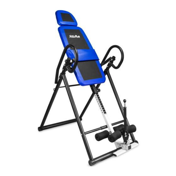
GRAVITY INVERSION THERAPY TABLE
ITEM: 96117
OWNER'S MANUAL AND SAFETY INSTRUCTIONS
SAVE THIS MANUAL: KEEP THIS MANUAL FOR SAFETY WARNINGS, PRECAUTIONS, ASSEMBLY,
OPERATING, INSPECTION, MAINTENANCE AND CLEANING PROCEDURES. WRITE THE PRODUCT'S
SERIAL NUMBER ON THE BACK OF THE MANUAL NEAR THE ASSEMBLY DIAGRAM (OR MONTH
AND YEAR OF PURCHASE IF PRODUCT HAS NO NUMBER)
FOR QUESTIONS PLEASE CALL OUR CUSTOMER SUPPORT: 909.628.0880 MON-FRI 9AM TO 3PM PST
Advertisement
Table of Contents

Subscribe to Our Youtube Channel
Related Manuals for Xtreme Power 96117


Summary of Contents for Xtreme Power 96117
- Page 1 GRAVITY INVERSION THERAPY TABLE ITEM: 96117 OWNER’S MANUAL AND SAFETY INSTRUCTIONS SAVE THIS MANUAL: KEEP THIS MANUAL FOR SAFETY WARNINGS, PRECAUTIONS, ASSEMBLY, OPERATING, INSPECTION, MAINTENANCE AND CLEANING PROCEDURES. WRITE THE PRODUCT’S SERIAL NUMBER ON THE BACK OF THE MANUAL NEAR THE ASSEMBLY DIAGRAM (OR MONTH AND YEAR OF PURCHASE IF PRODUCT HAS NO NUMBER) FOR QUESTIONS PLEASE CALL OUR CUSTOMER SUPPORT: 909.628.0880 MON-FRI 9AM TO 3PM PST...
-
Page 2: Important Safety Information
IMPORTANT SAFETY INFORMATION GENERAL SAFETY WARNINGS Read all safety warnings and instructions. Failure to follow the warnings and instructions may result in serious injury. Save all warnings and instructions for future reference. SAFETY The warnings, precautions, and instructions discussed in this instruction manual cannot cover all possible conditions and situations that may occur. -
Page 3: Product Information
PRODUCT INFORMATION The XtremepowerUs inversion therapy table is the secret super power to your health and fitness routine. This inversion table aims to combat nasty back aches, pains, and strains – but its benefits also extend to improving posture and circulation and increasing your flexibility. The XtremepowerUs inversion table was also designed with your comfort in mind. -
Page 4: Features And Specifications
FEATURES AND SPECIFICATIONS HEADREST BED FRAME HANDLEBAR PIVOT ARM ADJUSTABLE BOOM REAR U-FRAME ADJUSTMENT KNOB FOAM FOOT REST HEEL HOLDER FRONT FRAME FEATURES: Stimulate circulation; Elongate spine; Relieve pressure; Strengthen muscle; Increase flexibility Easy assembly & foldable; Heavy-duty steel frame with big non-slip bases Material: PU Leather Adjustable User Heights: 4'10"... - Page 5 PARTS LIST AND COMPONENTS...
- Page 6 ASSEMBLY STEP 1 Use the hex screw (14) and the flat fillet (15) to assemble the front preventing bracket (1). Adjust the angle, insert ASFE bar (4) into the back bracket’s (2) bores on the side. Following the direction shown above. Insert the hook into the bore.
- Page 7 ASSEMBLY STEP 2 Use the cross flat head screw (20) to mount the head table to the back bracket, then lock it. Use the hex screw (16) and flat fillet (15), nut (18) to assemble and lock the iron piece of the back bracket (5) and Z type bracket (12)
- Page 8 ASSEMBLY STEP 3 Use the cross flat head screw (20) to mount the head table to the back bracket (5), then lock it. Use the hex screw (16) and flat fillet (15), nut (18) to assemble and lock the iron piece of the back bracket 95) and Z type bracket (12).
- Page 9 ASSEMBLY STEP 4 Use the hex screw (14), the flat fillet (15), nut (18) to lock the horse (9) which is adjusted based on foot size with the height adjusting bracket (6).
- Page 10 ASSEMBLY STEP 5 Insert the height adjusting pipe (6) into the back bracket (5). Insert the drawing pin (22) and the draw pin with ring (21) into the related bore based on required height, then lock it tightly.
- Page 11 ASSEMBLY STEP 6 Use the hex screw (14), the flat fillet (15), nut (18) to assemble the left and right handrail (10) with the back bracket (2). To be safe, insert the pin with ring (21) into the rotating gear’s bore.
-
Page 12: Operation
OPERATION... -
Page 13: Warranty
WARRANTY PLEASE READ THE FOLLOWING CAREFULLY THE MANUFACTURER AND/OR DISTRIBUTOR HAS PROVIDED THE PARTS LIST AND ASSEMBLY DIAGRAM IN THIS MANUAL AS A REFERENCE TOOL ONLY. NEITHER THE MANUFACTURER OR DISTRIBUTOR MAKES ANY REPRESENTATION OR WARRANTY OF ANY KIND TO THE BUYER THAT HE OR SHE IS QUALIFIED TO MAKE ANY REPAIRS TO THE PRODUCT, OR THAT HE OR SHE IS QUALIFIED TO REPLACE ANY PARTS OF THE PRODUCT.
Need help?
Do you have a question about the 96117 and is the answer not in the manual?
Questions and answers