Table of Contents
Advertisement
Quick Links
Advertisement
Table of Contents

Subscribe to Our Youtube Channel
Related Manuals for ISOIL ISOMAG ML4-F1


Summary of Contents for ISOIL ISOMAG ML4-F1
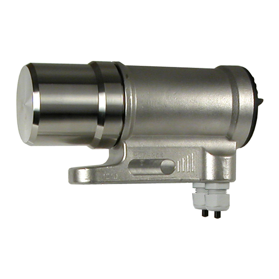
- Page 1 OPERATING AND INSTALLATION MANUAL CONVERTER ML4-F1...
-
Page 2: Table Of Contents
INDEX Introduction _______________________________________________________________________________pag.3 Symbols Used on the manual ________________________________________________________________pag.4 Technical characteristics ____________________________________________________________________pag.5 Electrical characteristics ____________________________________________________________________pag.5 Environmental conditions of use______________________________________________________________pag.5 Operative temperature _____________________________________________________________________pag.5 Overall dimensions ________________________________________________________________________pag.6 Electrical connections_______________________________________________________________________pag.7 Grounding instructions _____________________________________________________________________pag.7 Power supply converter ____________________________________________________________________pag.7 Electrical connections: input-output cables _____________________________________________________pag.8 Electrical connections: sensor cables __________________________________________________________pag.9 Inputs/outputs ___________________________________________________________________________ pag.10 Expansion modules _______________________________________________________________________ pag.11 Digital Input ____________________________________________________________________________ pag.12... -
Page 3: Introduction
INTRODUCTION This manual is integral part of the product. Read carefully the instructions contained since they give important indications for the safe use and maintenance. Technical information and relative products in this manual could undergo modifications without any previous notice. The flow meter must be used for what it has been built for. -
Page 4: Symbols Used On The Manual
Symbol Used on the manual ATTENTION DANGER ELECTRIC SHOCK WARNING PRECAUTIONS 4F1_EN_IS_0_3_5X.doc... -
Page 5: Technical Characteristics
TECHNICAL CHARACTERISTICS ELECTRIC CHARACTERISTICS Classification of the instrument: class I, IP 67, category of installation II Power supply Power supply current Pmax versions voltage 18÷30 Vdc 10 W INPUT/OUTPUT ISOLATION Input/output are insulated up to 500V The output 4÷20 mA and the output 24 Vdc are electrically connected ENVIRONMENTAL CONDITIONS OF USE The instrument can be installed inside or outside buildings Altitude: from –200 a 6000 m (from -656 to 19685 feet) -
Page 6: Overall Dimensions
OVERALL DIMENSIONS 4F1_EN_IS_0_3_5X.doc... -
Page 7: Electrical Connections
ELECTRICAL CONNECTIONS GROUNDING INSTRUCTIONS For the correct operation of the meter it’s NECESSARY that sensor and liquid are equipotential, so ALWAYS connect sensor and converter to the ground CONVERTER POWER SUPPLY before connecting the power supply, verify that the mains voltage falls between the limits indicated on the tag plate ATTENTION: the converters on dc power supply line are not protected against the inversions of polarity. -
Page 8: Electrical Connections: Input-Output Cables
ELECTRICAL CONNECTIONS: INPUT / OUTPUT CABLES OUTPUT 4÷20 MAINS POWER "A" RS485 PROFIBUS "B" RS485 PROFIBUS JACK FOR IF21 C. OUTPUT 1 E. OUTPUT 1 + INPUT 2 C. OUTPUT 3 - INPUT 2 E. OUTPUT 3 C. OUTPUT 2 E. -
Page 9: Electrical Connections: Sensor Cables
ELECTRICAL CONNECTIONS: SENSOR CABLES Dangers voltage: - 60 Vdc max - 250 V max commutation coil's circuit COIL 1 COIL 2 COMMON ELECTRODE 2 ELECTRODE 1 CABLES FROM SENSOR 4F1_EN_IS_0_3_5X.doc... -
Page 10: Inputs/Outputs
INPUTS / OUTPUTS Technical characteristic of OUTPUTS Output 1-2 17 (Out 1) 21 (Out 2) Max voltage 30 Vdc Max load:100 mA @24Vdc, Max. frequency: 1250 Hz. 18 (Out 1) 22 (Out 2) Output 3-4 / Input 2-3 Technical characteristic of OUTPUTS Max voltage 30 Vdc 19 (Out 3) Max load:100 mA @24Vdc,... - Page 11 (Output 0/4..mA) Power supply 18 ÷ 30 VDC Max load resistive to the output: 800 ohm with 24Vdc of power supply Minimum load recommended 500 Ohm Settling time : 5ms ATTENTION: The power supply of 0-4/20 mA is the same of that of 0/4..20mA OUT entire instruments , therefore is not insulated from it.
- Page 12 HOW WORK THE INPUT Input electric wiring Tmin Speed rate 10 K 20 Hz 110 ms 25 (+) 50 Hz 45 ms 60 Hz 40 ms 5/33 Vdc (ON) 80 Hz 30 ms 0/1,5 Vdc (OFF) 150 Hz 15 ms 300 Hz 10 ms 26 (-)
- Page 13 INPUT OPERATION STAGE (GENERIC FUNCTIONS) Auto-calibration Tmin<T<1sec. = autocalibration T > 1 sec. = Autozero AUTOCALIB. OFF Necessary conditions for enable the function 3-40 V • POS. 5.5 ENABLED • POS. 5.7-5.8-5.9 batch functions assign to input 1-2-3 (optional) DISABLED •...
- Page 14 OPERATION STAGE ON INPUT 1OR 2 OR 3 (BATCH FUNCTION) Start batch from remote input Necessary conditions for enable the function 3-40 V 0-1,5 V • POS. 5.7 ENABLE or POS. 5.8 or 5.9 on batch Opening Closing • POS. 6.1 ÷ 6.4 on end batch valve valve BATCH...
- Page 15 OPERATION STAGE ON INPUT 1 and 2 or 1 and 3 (BATCH FUNCTION) Start batch on remote input 1 stop from output selection formula 00 o 01 from remote input 2 Necessary conditions for enable the function Start 3-40 V 0-1,5 V •...
- Page 16 VISUALIZATION PAGES Flow rate value Analogical bar of flow rate variations % full scale Flow direction +/- See: anomalies codes and Date/time or alarm interpretation of flags Direct / reverse totalizer C=Calibration S=Simulation Sampling rate Flow speed Push to change visualisation Scale (1=low);...
-
Page 17: Flags Interpretation And Led
Flags interpretation and LED FLAGS INTERPRETATION FLAGS FLAG DESCRIPTION Alarm max activated Alarm min activated - Interruption coils circuit - Segnal error - Empty pipe Calibration running Simulation Pulse output saturation ( reduce TIME PULSE ) LED INTERPRETATION PERMANENT LIGHT: initialisation FLASHING LIGHT ( 1 sec.): normal function FLASHING LIGHT (<1 SEC.): alarm on The LED signals the real alarm status only if the display visualizes one of... -
Page 18: Keyboard
KEYBOARD SHORT PRESSING (< 1 SECOND): It increases the numeric figure or the parameter selected by the cursor It goes to the previous subject on the menu batch start/stop (when enabled) LONG PRESSING (> 1 SECOND): It decreases the numeric figure or the parameter selected by the cursor It goes to the next subject on the menu SHORT PRESSING (<... -
Page 19: Access Codes
FACTORY PRE-SETTINGS ACCESS CODES ACCESS CODES Some functions in the converter are enabled by the access codes. The information of this manual are related to all the The converter is delivered with access code L2: functions available with L2 level. All the functions available through higher level are protected and reserved to the service. - Page 20 ML4F1 Functions (for detail functions with symbol “*”see the manual from page 25) Attention: The function in grey colour are visualized on display only with other active functions or with optional modules Insert ND of sensor ( 0-3000 ) 1.2 Calibration data of sensor visualized on sensor’s label 1.3 Type of sensor: Enter the first two characters of the serial number of the sensor 1.4 Position for insertion sensors: 0=1/8DN, 1=1/2DN, 2=7/8DN 1.5 Factory parameter...
- Page 21 5.1* Total direct (positive) flow totalise reset enable 5.2* Partial direct (positive) flow totalise reset enable Functions assigned 5.3 Reset totalise of pulse from digital input (see page 13) On input 1 5.4 Totalise counting lock command (see page 13) 5.5* Autozero calibration external command 5.6 Range change external command (se pos.
- Page 22 Menu 9: Menu visualized only IF batch is active (see from pag. 31) 9.1* Number of batch cycles to be done to define the value of compensation. 9.2* % limit of compensation threshold 9.3* Compensation value 9.4* Prebatch value 9.5* Auto-batch 9.6* Automatic selection of batch formula 9.7* Static consent of batch 10.1* Enable the calibration of the converter...
- Page 23 ACCESS TO THE CONFIGURATION MENUES The access to the configuration menu can take place in two different modes: Through the “Quick start menu” where it is possible to access directly to some of the principal functions Through the “Main menu” where it is possible to access to all function with access code ≤...
- Page 24 EXAMPLE: modifying the full scale value from 4dm³/s to 5dm³/s. from “Main Menu” (quick start menu enable) Enter in the “Quick start menu” Access to the “Main Menu” X 5 TIMES Access to the “Scale” menu Access to the function “Fs1” Push repeatedly Confirm the new value...
-
Page 25: Functions Description
FUNCTIONS DESCRIPTION (description of the functions with access code< 3) Function enabled only with another enabled function or with optional module Identification of the function (not visualized on display) MENU 1.SENSOR * (POS. 1) Nominal diameter of sensor [ND= XXXX] Converter request Menu visualized on the converter ( from 1 to 11) Synthetic description of the function... - Page 26 Cubic centimetre Cubic inch Gram Millilitre American gallon Kilogram Liter British gallon Cubic decimeter Cubic foot Decalitre Standard barrel Ounce Hectolitre Oil barrel Pound Cubic metre Cubic yard short tons KAmerican gallon KBritish gallon When a mass unit of measure is set, the specific gravity function is automatically enabled by the system.
- Page 27 and a variation form 10% to 100% exceeding the acceleration threshold and then immediately sent to the output. In actual fact there is always a minimum time between the measure acquisition and the outputs update. (POS. 3.4) Peak cut off threshold [PEAK THR=% XXX] Anomalous signal pick cut off threshold set.
- Page 28 MENU 5.INPUTS (POS. 5.1-5.2) Modify/reset totalizer enable [T/P+RESET=ON/OFF] From visualisation pages, proceed in the following mode: Push the key , Set the L2 CODE if required and then push the key from visualization page, at the required “RESET TOTALIZ.?” Push the key and then the key to confirm or any other key to cancel this operation...
-
Page 29: Batch
T. OFF phase = T. total cycle - pulse duration N.B. : If duty cycle value is set to 0, the pulses emissions is synchronized with the flow rate ; set this value in case you need the pulses like “frequency out” (POS. - Page 30 (POS. 9.3) Compensation value [V.COM.=XX.XXX] This value, expressed in the same selected volume unit of measure, is the result of the difference between the batch value set and the quantity of product really supplied due to the system delays: closing valves, stop pumps, stop motors, etc. Attention: if you need to set manually the value of compensation, preset to ZERO the Number of batch samples (POS.
-
Page 31: Enable Batch
BATCH FUNCTION. ENABLE BATCH Enable one of the following functions to enable and program the batch on the converter: POS. 5.7-5.8-5.9: START/STOP batch from input POS. 6.1-6.2-6.3-6.4: assign one of the functions to one of two output Some examples of operation of such functions are visualized from page 14 VISUALIZATION PAGE WITH BATCH FUNCTION ENABLE Programming formula n°... -
Page 32: Start Stop Batch
START STOP BATCH START: it is possible activate the start of batch in two different way: from remote input: assigning the functions of start/stop batch to the input 1 (POS. 5.7) or input 2-3 (POS. 5.8-5.9) and using the input/s like visualized from page 14. from keyboard: short pressing of the key N.B.: the start of batch from keyboard is always on the descent front (release of the key) and is not available with the function of batch consent (POS. -
Page 33: Causes And Actions To Be Taken
Alarm messages, causes and actions to be taken Messages ANOMALIES ACTION TO TAKE NO ALARMS All works regularly ----- Check the maximum flow rate threshold set and the MAX ALARM The flow rate is higher than the maximum threshold set process conditions Check the minimum flow rate threshold set and the MIN ALARM... - Page 34 DECLARATION OF CONFORMITY Isoil Industria SpA it declares under the own responsibility that the product: Model converters ML4F-1 Model sensors MS 500 – MS 501 – MS 600 – MS 1000 – MS 2410- MS 2500 – MS 3700 MS 3770 – MS 5000...
- Page 35 4F1_EN_IS_0_3_5X.doc...
- Page 36 N o r t h A me r i c a D i s t r i b u t i o n : F L O MO T I O N S Y S T E MS I n c . 3 N .
Need help?
Do you have a question about the ISOMAG ML4-F1 and is the answer not in the manual?
Questions and answers