Table of Contents
Advertisement
OPERATING AND MAINTENANCE MANUAL
ELECTROMAGNETIC FLOWMETER
CONVERTER
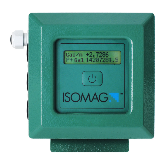
MODEL: ML 145
Release number: 145_EN_IS_R0_3.00.0XXX.docx – The characters of file name in
bolt type indicate the software version which the manual refers to; it is visualized at the
instrument start up, or by specific function on DIAGNOSTIC menu.
Advertisement
Table of Contents

Related Manuals for ISOIL ISOMAG ML 145


Summary of Contents for ISOIL ISOMAG ML 145
- Page 1 OPERATING AND MAINTENANCE MANUAL ELECTROMAGNETIC FLOWMETER CONVERTER MODEL: ML 145 Release number: 145_EN_IS_R0_3.00.0XXX.docx – The characters of file name in bolt type indicate the software version which the manual refers to; it is visualized at the instrument start up, or by specific function on DIAGNOSTIC menu.
-
Page 2: Table Of Contents
INDEX INTRODUCTION ......................3 SAFETY INFORMATIONS ................... 3 TECHNICAL CHARACTERISTICS ................5 ELECTRIC CHARACTERISTICS ..............5 ENVIRONMENTAL USE CONDITIONS ............... 5 TORQUES ...................... 5 OVERALL DIMENSIONS AND WEIGHTS ............6 CONVERTER POWER SUPPLY..................7 MEASUREMENT SETTINGS ..................11 POWER CONSUMPTION ................12 ELECTRICAL CONNECTIONS ................... -
Page 3: Introduction
INTRODUCTION These operating instructions and description of device functions are provided as part of the scope of supply. They could be modified without prior notice. The improper use, possible tampering of the instrument or parts of it and substitutions of any components not original, renders the warranty automatically void. - Page 4 The Operating Instructions provide detailed information about the converter. If you are unclear on anything in these Operating Instructions, you must call the ISOIL service department. Repairs may only be performed if a genuine spare parts kit is available and this repair work is expressly permitted.
-
Page 5: Technical Characteristics
TECHNICAL CHARACTERISTICS ELECTRIC CHARACTERISTICS Instrument classification: class I, IP 67, overvoltage category II, rated pollution degree 2 Power supply Power supply version Power supply frequency power 18-30V LITHIUM BATTERY 3.6V-19Ah 200mW RECHARGEABLE * Voltage variations must not exceed ±10% of the nominal one. ENVIRONMENTAL USE CONDITIONS The converter can be installed internally or externally ... -
Page 6: Overall Dimensions And Weights
OVERALL DIMENSIONS AND WEIGHTS CABLEGLAND PG11 PG11 CAP QUICK CONNECTOR LAYOUT AND QUANTITY IN ACCORDING TO ORDER CODE Aluminium housing weight: 3Kg; Stainless steel housing weight: 3.5kg Weights refer to the converter without battery (each battery weights 0.1kg), which can be provided with 6 batteries maximum and without display, blind configuration. -
Page 7: Converter Power Supply
CONVERTER POWER SUPPLY ML145 can be supplied in three different mode: by batteries by mains voltage OPTIONAL by solar panel (APL) OPTIONAL Below are shown the Terminal on PCB of the three different power supply Solar panel APL Main voltage Batteries... - Page 8 POWER SUPPLY BY BATTERIES B1 CONVERTER BATTERY B2 CONVERTER BATTERY To replace the batteries contact the service Note : Lithium batteries are subject to special transportation regulations according to “Regulation of Dangeroug Goods, UN3090 and UN 3091”. Special documentation is required to observe there regulations.
- Page 9 POWER SUPPLY BY MAINS VOLTAGE (OPTIONAL) Before connecting the power supply, verify that the mains voltage is within the limits indicated on the data plate. For the connections use only approved conductors (unsheathed as few as possible), with fire-proof properties, whose section varies from 0.25mm to 2.50mm , based on distance/power;...
- Page 10 POWER SUPPLY SOLAR PANEL APL (OPTIONAL) Solar Panel Connector ML145 board (example) The APL module allows to power up the instruments of Flowiz family through a photovoltaic module. The system is composed by : One photovoltaic panel that converts directly sunlight into electrical energy •...
-
Page 11: Measurement Settings
MEASUREMENT SETTINGS The ML 145 converter can be programmed to measure in four different profiles: FLOWRATE PROFILE VARIABLE CONSTANT VARIABLE Measures at maximum sample rate CONTINUOS SAMPLING Max S.R. Max S.R. Max S.R. Automatic Sample rate according to flow profile SMART SAMPLING 5 Sec. -
Page 12: Power Consumption
POWER CONSUMPTION The batteries consumption depends from the setting of the followings elements: main board, sampling interval (measure profile), sensor diameter, frequency of data delivery, amount of data collected, interface activities (display). Special software to calculate the consumption is available; here below a simple scheme to evaluate the different “consumption’s rate”... - Page 13 POWER TOOL SOFTWARE Power tool is a software which allows to evaluate the converter battery life. The estimation is done with easy guided procedure Low power consumption: a number of design strategies have been employed to achieve exceptionally low power consumption. However, the length of time between battery changes depends on a quality/status of batteries, the frequency of sampling and logging.
-
Page 14: Electrical Connections
ELECTRICAL CONNECTIONS INTERNAL VIEWS OF THE CONVERTER SOCKET FOR ALTERNATIVE POWER SUPPLY (SOLAR PANEL OR COMMERCIAL BATTERIES) SWITCH ON/OFF CONVERTER DIP-SWITCHES TERMINAL SOCKETS FOR BATTERIES TERMINAL SOCKETS FOR IF23 The sensor, hardwired inputs and outputs are connected to the converter through the terminal blocks. - Page 15 TERMINAL BLOCKS M1 OUTPUTS COMMON ELECTRODES COILS INPUT 4÷20 OUT OUT1 OUT2 LEGEND E1-2: electrode 1-2 B1-2: coil 1-2 C: common SH: Cable shield, electrically connected to ground and to the housing...
-
Page 16: Sensor-Converter Connections
SENSOR-CONVERTER CONNECTIONS SEPARATE VERSION WITH NORMAL CABLES ALL SENSORS SEPARATE VERSION WITH CONNECTORS C+SH ALL SENSORS CABLES MUST BE PLACED INSIDE A METALLIC CONDUIT AND ELECTRICALLY CONNECTED TO THE CONVERTER HOUSING AND GROUND (EARTHED)! MAX CABLE LENGTH: 20m NOTICE: sudden movements of the electrode cable can cause noise on the measure. -
Page 17: Optional Digital Input
OPTIONAL DIGITAL INPUT INPUTS INSULATION Inputs are insulated up to 500V ELECTRIC WIRING SW : switch for internal input power supply, see above its location 3.3V 3.3K Input ON/OFF INPUT FUNCTIONS Several functions of the converter can be controlled through the application of an input voltage (see menu input);... -
Page 18: Optional Digital Outputs
OPTIONAL DIGITAL OUTPUTS OUTPUTS INSULATION outputs are insulated up to 500V DIGITAL OUTPUT Technical characteristics (OUT1) (OUT2) Opto-insulated output (Opto-MOS) Maximum switching voltage: 40V /28V~ Maximum switching current: 100mA Maximum Ron = 70 Maximum switching frequency (load ... - Page 19 DISPLAY FLAGS FLAGS At ‘Power on’ of the converter, the user will see the following display screen. In the top right hand corner there a range symbols. symbols interpreted from table below. Interpretation of the flashing LED can be made from the LED Interpretation table at the bottom of this page.
-
Page 20: Access To The Converter Keypad
ACCESS TO THE CONVERTER KEYPAD KEYPAD SHORT PRESSING (< 1 SECOND): Change the display of the process data LONG PRESSING (> 1 SECOND): Wake up display SCREENS DISPLAYED Note: The user will see the screen displayed (below) at power on. Use the key as indicated to move between the screens. -
Page 21: Flow Rate Visualization
FLOW RATE VISUALIZATION The ML 145 can show a 5 digit character display for flow rate units. The maximum flow rate value that can be displayed is 99999 (irrespective of and subsequent decimal point positioning), the minimum is 0.0001 The converter’s maximum allowable flow rate is based on the following formula calculation relating to the pipe Nominal Diameter: ND x ND x 0.008 The result of above calculation gives the maximum flow rate at a liquid flow... -
Page 22: Access To The Configuration Menus
ACCESS TO THE CONFIGURATION MENUS The converter’s configuration menus can be accessed only by ISOCON interface ACCESS TO THE CONFIGURATION MENUS BY ISOCON INTERFACE Isocon allow to set all the converter functions; see suitable manual for more details. (Cable and software required) Being the housing closure dependent by the installer, the IP degree may be compromised, so follow the torques mentioned. - Page 23 : “Quick start menu” function modification. Full scale value 1 EXAMPLE (Fs1) from 4dm³/s to 5dm³/s. Access the function “Fs1” Enter in the “Quick start menu” Push the key repeatedly to move To increase the value press the the cursor to the value to modify upper key leave the quick start menu and Confirm the new value...
- Page 24 EXAMPLE: “Main menu” function modification. Full scale value 1 (Fs1) from 4dm³/s to 5dm³/s. (Quick start menu enabled) Access to the “Main Menu” Press the button indicated Enter in the “Quick start pressing to enter the Main menu menu” indicated page screen from the Quick From any page of the start-up menu page...
-
Page 25: Security On Functions Access
SECURITY ON FUNCTIONS ACCESS ACCESS CODE Functions in the converter main menu are enabled by the access codes. The information of this manual is related to all the functions available with the L2 level. All the functions available through higher level are protected and reserved to the service. L2 code = 000000 disable the request of L2 code L2 customized (6 digits freely chosen by the user) you can program all the functions up to L2;... -
Page 26: Ml 145 Main Menu Functions
ML 145 MAIN MENU FUNCTIONS (functions with access code< 3, those with symbol “*” see from page 29) Attention: The menu functions in grey colour are visualized on display only with other active functions or with optional modules F U N C T I O N ’ S L I S T Insert ND of sensor (0-3000) Calibration data of sensor visualized on sensor's label Sensors model: Enter the first two characters of the serial number of the sensor... - Page 27 5.1* Total direct (positive) flow totalise reset enable 5.2* Partial direct (positive) flow totalise reset enable 5.3* Total reverse (negative) flow totalise reset enable 5.4* Partial reverse (negative) flow totalise reset enable 5.5 Totalise counting lock command 5.6* Autozero calibration external command 5.7 Input power supply ( ON = input power supply from internal battey) 5.8 Alarm from external signal (i.e.
- Page 28 9.1* Date and time set 9.2* Automatic data logger enable 9.3 Choice of single (off) or double (on) interval 9.4 Interval time 1 for the data logging function 9.5 Interval time 2 for the data logging function 9.6 Interval period 2 for the data logging function 9.7 Interval 2 start loggin time 9.8 Interval 2 stop loggin time 9.9 Enables the direct total totalizer...
-
Page 29: Functions Description
FUNCTIONS DESCRIPTION (description of the functions with access code< 3) Identification of the function (not visualized on display) MENU 1.SENSOR (POS. 1.1) Nominal sensor diameter [ND= XXXX] LIVELLO ACCESSO: 2 Converter request Immissione del diametro nominale del sensore.Deve ……….. Menu visualized on the converter (from 1 to 11) Synthetic description of the function MENU 1 - SENSOR (POS. - Page 30 Available mass and volume units Cubic inch Ounce Cubic centimetre American gallon Millilitre Pound Imperial Gallon short tons Litre Cubic foot Cubic decimetre Standard barrel Decalitre Oil barrel Gram Hectolitre Imperial Kgallons Kilogram Cubic metre US Kgallons Acre feet USA Mega Gallons Imperial Mega Gallon When a unit of mass is selected, the specific gravity function is automatically enabled.
- Page 31 MENU 5 - INPUTS (POS. 5.1-4) Enable reset partial/total totalizers [T+-/P+- reset= ON/OFF] When this function is ON, the totalizers could be zeroed remotely. (POS. 5.6) Autozero calibration external command enable [Calibration=ON/OFF] This function enables/disables the automatic zero calibration system. When this function is active, applying a voltage on the meter’s on/off input terminals performs an autozero calibration cycle.
- Page 32 USING DATA LOGGER BY ISOCON INTERFACE Data are stored on micro SD card; the organization is based on “tree-structure”: the system create a daily folder where it save events and data logger . The data can be downloaded using ISOCON interface. The measure sampling interval is influenced by the data logger interval;...
- Page 33 EXAMPLES Events download To read events from SD memory card: flag the Show file option and click on the related reading command. Confirm (or change to view past events, if there are) the file name and click OK. Data logger download To read data logger from SD memory card: flag the Show file option and click on the related reading command.
- Page 34 Board temperature, measure unit and value. Blank to future expansion Battery 2 status, symbol and value Battery 1 status, symbol and value Measure cycles/hour, symbol and value Blank to future expansion Partial net value totalizer, measure unit and value Total net value totalizer, measure unit and value Partial negative totalizer, measure unit and value...
- Page 35 Note: it is recommended the date synchronization between converter and pc to perform correctly the events and logger reading operations. File download To read any file from SD memory card: flag the Show file option and click on the related reading command.
-
Page 36: Alarm Messages, Causes And Corrective Actions
Alarm MESSAGES, CAUSES AND CORRECTIVE ACTIONS In case of alarms/anomalies check immediately the wiring status. to see the each any alarm message push the key Number/quantity of alarms Alarm message CODE MESSAGE CAUSE ACTION NO ALARMS ----- ----- CALIBRATION ERROR Internal calibration error If the error is persistent, replace the board The SD card installed is missing, not valid or not... -
Page 37: System Error Codes (Start-Up/Events Log)
SYSTEM ERROR CODES (start-up/events log) (they may be summed together in hexadecimal codes as for example: 0002+0004+0008 = 000E) CODE ANOMALIES DESCRIPTION ACTION 0001 Keyboard error (key stuck detected) 0002 Hardware parameters stored in F-RAM not valid 0004 Sensor parameters stored in F-RAM not valid 0008 Converter parameters stored in F-RAM not valid ADDRESS TO SERVICE... -
Page 38: Appendix 1 Display Rotation Procedure
APPENDIX 1 DISPLAY ROTATION PROCEDURE Pic.4 Pic.5 Fixing screw of board Pic.1 Display Verify the absence of power supply, set the Rotate the display to the desired location, converter in stand-by, remove batteries verify the correct set of the seal, the cleaning of the contact surfaces and place the display in ... -
Page 39: Appendix 2 Battery Substitution
APPENDIX 2 BATTERY SUBSTITUTION FIXING SCREW OF BATTERY GROUP FIXING SCREW BOARD - Verify the absence of power supply - Set the converter in Stand-by (menu 10) - Extract the battery group unscrewing the frame screws - Remove the battery connectors - Mount the new batteries frame - Re-connect the batteries group connectors Batteries connectors... -
Page 40: Isomag Return Material Form
SERVICE: return form for instrument repair or calibration ISOMAG RETURN MATERIAL FORM AND CLEANING UP CERTIFICATE RMA n°_______ Shipping Address: ISOIL INDUSTRIA S.p.A. Via Piemonte, 2 35044 MONTAGNANA (Padova, Italy) Dear Friend, to improve the SERVICE QUALITY and the SAFETY, please read, complete and attach this document (RMA) to the material you intend to send. - Page 41 Please note that the instruments sender will be charged for any necessary cleaning costs. Additionally, we reserve the right to send the instruments back to the sender for cleaning! Please kindly state the observed failure and, eventual causes. Sensor: MS______________ Serial number:__________________________ Failure description:_______________________________________________ Converter: ML______________ Serial number:______________________...
-
Page 42: Transportation Document
TRANSPORTATION DOCUMENT (Road part – In accordance with ADR) Sender Refer document DDT (Delivery note) n. :___ of:_______ Destination Description of the goods ONU Number UN 3091 Official Description METAL LITHIUM BATTERY IN EQUIPMENT Class Group of packing Tunnel Code restriction Packing ____________________ Total quantity of dangerous goods: net weight (each... -
Page 43: Conformity Declaration
CONFORMITY DECLARATION ISOIL Industria spa declares that the product line: converter model: ML 145 and sensor models: MS 501 – MS 600 – MS 1000 – MS 2410 – MS 2500 – MS 3770 – MS 3800 – MS 5000...
Need help?
Do you have a question about the ISOMAG ML 145 and is the answer not in the manual?
Questions and answers