Huawei NE05E Series Quick Installation Manual
19inch&21inch cabinet
Hide thumbs
Also See for NE05E Series:
- Hardware manual (547 pages) ,
- Quick installation manual (30 pages) ,
- Quick installation manual (24 pages)

Subscribe to Our Youtube Channel
Related Manuals for Huawei NE05E Series


Summary of Contents for Huawei NE05E Series
- Page 1 NE05E&NE08E Series Quick Installation Guide(19inch&21inch cabinet) Issue: 05 Date: 2020-08-31 HUAWEI TECHNOLOGIES CO., LTD.
- Page 2 The purchased products, services and features are stipulated by the contract made between Huawei and the customer. All or part of the products, services and features described in this document may not be within the purchase scope or the usage scope.
-
Page 3: Installation Flow
Installation Flow... - Page 4 Precautions NOTE This document provides simple and distinctive guidelines for quick hardware installation of the NE05E&NE08E(NE05E-SR/S2/SE/SF/SG/SH/SI/SQ&NE08E-S6/S6E/S9). Based on the height of a device, the NE05E-SR/S2/SE/SF/SG/SH/SI/SQ are considered 1 U devices, and the NE08E-S6/S6E are considered 2 U devices, and the NE08E-S9 are considered 3 U devices.
-
Page 5: Tools For Installation
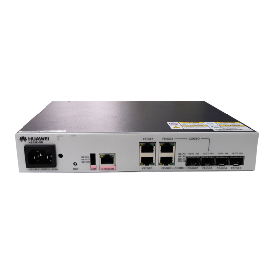
Tools for Installation Level Bar Tape Measure Philips Screwdriver Flathead Screwdriver Punching Wire pliers (M2-M6) (M2-M6) Network Cable Paper Knife Ratchet Crimp Diagonal Pliers Cable Cutter Crimping Pliers Tool Wire Stripper Cord end Sharp-nose Pliers Coax Stripper Marker Pen terminal crimper Bayonet Wrench Adjustable Wrench Binding Strap... - Page 6 Introduction to the 1U-height Chassis NE05E-S2 NM interface Power supply Antistatic jack interface PGND point (Console interface) interface Clock and time interface FE/GE optical Alarm interface GE optical interface interface SHDSL interface T1 interface FE/GE electrical interface NE05E-SE/NE05E-SF 10GE optical interface Power supply NM interface PGND point...
- Page 7 NE05E-SG/NE05E-SH/NE05E-SI/NE05E-SQ NM interface Power supply interface GE optical interface PGND point (Console interface) Clock interface FE/GE optical Alarm interface Time interface interface Electrical interface E1 interface Clock interface Antistatic jack interface NM interface Power supply interface (Console interface) 10GE optical interface FE/GE optical interface Alarm interface FE/GE electrical interface...
- Page 8 Introduction to the 2U-height Chassis NE08E-S6 Power supply interface Antistatic jack interface NM interface Clock interface (Console interface) Time interface Alarm interface GE optical interface PGND point E1 interface Electrical interface NE08E-S6E Power supply interface Antistatic jack interface NM interface Clock interface (Console interface) Time interface...
- Page 9 Introduction to the 3U-height Chassis NE08E-S9(DC) NM interface Power supply interface Antistatic jack interface Clock interface (Console interface) Time interface Alarm interface GE optical interface PGND point E1 interface Electrical interface NE08E-S9(AC) NM interface Power supply interface Antistatic jack interface Clock interface (Console interface) Time interface...
-
Page 10: Installing The Chassis
Installing the Chassis Scenario I: Installing the Chassis in the 19-inch Cabinet Installing the floating nut Floating nuts Mount bar (Use a Flathead Screwdriver if no mount bar is available) Installation holes for the floating nut: The three When fixing the floating nuts, keep a distance of at holes with even spacing equal a 1-U height. - Page 11 Scenario I: Installing the Chassis in the 19-inch Cabinet Connecting the PGND cable NOTE The cabinet column houses ground screw holes. One end of the ground cable is fixed at the device, and the other end can be fixed at a close grounding point or grounding bar in the equipment room based on the actual requirements.
- Page 12 Scenario II: Installing the Chassis in an ETSI Cabinet Installing the floating nut Mounting rail of the ETSI cabinet Floating nut 25mm Mount bar (Use a Flathead Screwdriver if no 25mm mount bar is available) When fixing the floating nuts, keep a distance of at A 1 U device corresponds to holes 1-2, and a 2 least 25 mm on both the left and right sides of the NE U device corresponds to holes 1-3.
- Page 13 Scenario II: Installing the Chassis in an ETSI Cabinet Connecting the PGND cable NOTE The cabinet column houses ground screw holes. One end of the ground cable is fixed at the device, and the other end can be fixed at a close grounding point or grounding bar in the equipment room based on the actual requirements.
-
Page 14: Connecting And Routing Cables
Connecting and Routing Cables Common Cables for the Chassis AC power cable DC power cable PGND cable Fiber Shielded network cable E1 cable (120-ohm ) E1 cable (75-ohm) Installing the Power Cable Installing the AC Power Cable the cable tie NOTE •Insert the power plug, and use the cable tie to fix the plug connected to the device, preventing the plug from getting loose or falling off. - Page 15 Installing the Power Cable Installing the DC Power Cable 1U-height DC chassis 1U-height chassis 2U-height chassis (NE05E-SQ) use a screw to fix the OT BGND power cable terminal of the DC power cable Positive pole: + -48V power cable BGND power cable at the DC power interface Negative pole: - Positive pole: +...
- Page 16 Connecting the E1 Cable NOTE When installing and routing cables, refer to the engineering document on site to install and connect the E1 cable, service network cable, and fiber at the opposite end. CAUTION •The NE05E-SH must use the matching E1 cables. The 75-ohm 8 x E1 cable of other types of NE equipment cannot be used for the NE05E-SH.
-
Page 17: Connecting Fibers
Connecting Fibers WARNING Laser When handling optical fibers, do not stand close to or look into the optical fiber outlet directly with naked eyes. NOTE •It is recommended to connect the fibers to optical interfaces from the left to right. •... - Page 18 Connecting the Network Management Cable NOTE •The NMS cable is a serial cable and has different pin arrangement than a common network cable. •For details about connecting a serial cable, see Installation the "Making a Serial Cable" in the Guide ETH/OAM Connecting the External Clock/Time Cables NOTE...
- Page 19 Cable Layout Effect of the Chassis AC Equipment: DC Equipment: NOTE •Connect the cables of the same type to the interfaces on the chassis in a sequence from left to right. •Routing cables upward is recommended. •The preceding figure shows the cable layout effect of the NE05E-SI and NE08E-S6 equipment installed in a 19-inch cabinet.
- Page 20 Checking Cable Connectivity Checking Connectivity of E1 Cables NM center Loopback Transmission network 1. An hardware installation engineer powers on the device, sets up optical paths, and informs a software commissioning engineer in the network management (NM) center that the device is powered on and optical paths are set up.
-
Page 21: Installation Checklist
Installation Checklist Item The chassis are positioned in the proper place as prescribed by the engineering design specific to the site. When the chassis is installed in a 19-inch cabinet, make sure that the chassis does not come into contact the front door and that the cables are not pressed against the front door when it is closed. Each chassis component does not have any paint drop, damage, or stain. -
Page 22: Powering On The Equipment
Powering On the Equipment Powering On the Equipment Check the voltage and the fuse capacity of the external power supply NOTE For running an AC NE05E-SQ, you must turn on the switches of both AC power modules operating in 1+1 backup mode. Standard Voltage of the Input Power Supply Allowed Voltage Range for Equipment... - Page 23 Check the power-on status Use the NE05E-SI as an example for an AC device: The board hardware is faulty Indicator State Description State Description Indicator On and green The power supply is normal. The power supply fails. STAT On and green The board is working normally.
- Page 24 Checking Tail Fiber Connection External cable Fiber jumper connected to the OUT port Optical power Optical power meter meter NOTE •To check tail fiber connection, you need to check the deviation of the optical power between an optical interface on the board and the peer interface on the ODF. If the optical power meter reads a value less than or equal to dB, it indicates that the tail fiber connection is correct.
- Page 25 Appendixes Assembling OT Terminals Material: OT terminals (ring terminals) , heat-shrinkable tube and cable. Press the end of the contact terminal on the Strip a part of the jacket off the cable to expose conductor by using the crimping tool. the conductor with a length of L1.
- Page 26 AC/DC power system (ETP4830-4815AF power system) •To ensure that the power supply of the equipment is not interrupted, you can also connect the device to batteries. Then, if the mains supply is interrupted, the device can be powered by batteries. •A storage battery array consists of four 12 V -40 Ah storage batteries.
- Page 27 HW-100-48AC14D-1 Power System The HW-100-48AC14D-1 power system supports AC power ranging from 90 V to 264 V, and outputs -48 V DC power for NE05E-S2/SE/SF/SG/SH in natural heat dissipation mode. Colour of cables Pole Black Bule Single channel of -48 V input power Two channels of -48 V input power To provide two channels of -48 V input power, remove the terminal of one channel and connect the channel to the available binding post in the terminal of the other...
- Page 28 ETP4830-B1A2 Power System The ETP4830-B1A2 external power system converts input 220 V AC power to -53.5 V DC power and supplies power to the NE. NE08E ETP4830-B1A2 220 V AC power input interface Interfaces and air breakers on the front panel of the ETP4830-B1A2 Interface Number of Type...
Need help?
Do you have a question about the NE05E Series and is the answer not in the manual?
Questions and answers