Advertisement
Quick Links
H
O
Hot Runner System Installation Guide
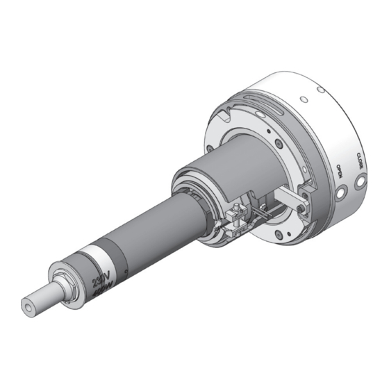
Service and Maintenance / Single Axis Valve Gate Nozzle 16SVH
10.3.2 Single Axis Valve Gate Nozzle 16SVH
Doc007360.png
NOTICE
To ensure long life and continued flawless operation of the actuator, we recommend using a service medium that
complies with the requirements of classification 21/18/13 pursuant to ISO 4406.
Master Language is English
RESTRICTED: Property of Synventive.
For limited third party distribution based on need and intended use.
T
R
U
N
N
Hot Runner System Installation Guide
E
R
T
E
C
Technical Data
Valve pin operation
Operation medium
Pressure range
Flowrate
Reaction time
Valve pin stroke:
Adjustment
Closing force
Opening force
Connection
Valve pin
Valve pin diameter
Attachment
Heating Power
Zone 1
(From a nozzle length of
100 mm)
Zone 2
(From a nozzle length of
120 mm)
Zone 3
(From a nozzle length of
370 mm)
Head
EN
- 379 -
H
N
O
L
O
G
hydraulic
40 - 60 bar (580 - 870 psi)
2.5 l/min
~0,5 s
14 mm
± 1 mm
Via adjustment threads from
outside.
4984 N / 40 bar (580 psi)
4043 N / 40 bar (580 psi)
M12x1,5 (8-L)
Ø 8 mm
Quick coupling, anti-rotation
The numbering of the heating
zones starts at the nozzle tip
and ends at the nozzle head.
400 Watt
558 - 1030 Watt
1188 - 1230 Watt
800 plus 680 Watt
SVC-17-0001_EN-Rev11
All rights reserved. Errors and omissions excepted
© 2019 Synventive Molding Solutions
Y
Advertisement

Related Manuals for Synventive 16SVH

Summary of Contents for Synventive 16SVH
- Page 1 Hot Runner System Installation Guide Service and Maintenance / Single Axis Valve Gate Nozzle 16SVH 10.3.2 Single Axis Valve Gate Nozzle 16SVH Technical Data Valve pin operation Operation medium hydraulic Pressure range 40 - 60 bar (580 - 870 psi) Flowrate 2.5 l/min...
- Page 2 Hot Runner System Installation Guide Service and Maintenance / Single Axis Valve Gate Nozzle 16SVH Technical Data / Exploded View - Cooling Unit CU16SVH01 NOTICE If the mold temperature is 80 °C (176 °F) or more, the Cooling Unit CU16SVH01 is required.
- Page 3 Hot Runner System Installation Guide Service and Maintenance / Single Axis Valve Gate Nozzle 16SVH 10.3.2.1 Single Axis Valve Gate Nozzle 16SVH Parts List In this section the nozzle parts are identified with the numbers indicated in the following figure.
- Page 4 Hot Runner System Installation Guide Service and Maintenance / Single Axis Valve Gate Nozzle 16SVH Actuator HYC2314S01 Parts List Doc003305.png Pos. Qty. Description Part Number Actuator housing HYC2314CH01 Piston D23 HYC2314PI01 Gasket locator HYC2314GL01 Gasket locator cover HYC2314GC01 Suspension ring...
-
Page 5: Assembly Tools
Hot Runner System Installation Guide Service and Maintenance / Single Axis Valve Gate Nozzle 16SVH Assembly Tools In this section the Stripping and Mounting Tool parts are identified with the numbers indicated in the following figure. Nozzle Disassembly Tool Pos. - Page 6 Hot Runner System Installation Guide Service and Maintenance / Single Axis Valve Gate Nozzle 16SVH Safety Instructions for the Service at the Single Axis Valve Gate Nozzle 16SVH Hot Surfaces Hazard Contact between the skin and hot surfaces could result in burns.
- Page 7 Hot Runner System Installation Guide Service and Maintenance / Single Axis Valve Gate Nozzle 16SVH 10.3.2.2 Dismounting the Hydraulic Cylinder Housing and Sealing 1) Remove the socket head cap screw (16). 2) Remove the dasher and grounding cable. Doc007414.png 3) Unlocked the Hexagon socket cap screws.
- Page 8 Hot Runner System Installation Guide Service and Maintenance / Single Axis Valve Gate Nozzle 16SVH 7) Remove the isolation nut (1). 8) Lift the complete actuator housing (8) from the guide sleeve (9). Doc007285.png 9) Unscrew the suspension ring (HYC2314SR01).
- Page 9 Hot Runner System Installation Guide Service and Maintenance / Single Axis Valve Gate Nozzle 16SVH 12) At the 3 pistons (02) loosen and remove the gasket locators (03) with the wrench ATCYL1005 (T5). 13) Pull the pistons (02) out of the cylinder housing (01).
- Page 10 Hot Runner System Installation Guide Service and Maintenance / Single Axis Valve Gate Nozzle 16SVH 10.3.2.3 Assembly of the Cylinder Housing HYC2314S01 on the Nozzle Assembly of the Pistons into the Actuator HYC2314S01 NOTICE After disassembly of the sealing elements, the original seals should be replaced as required by Synventive.
- Page 11 Hot Runner System Installation Guide Service and Maintenance / Single Axis Valve Gate Nozzle 16SVH 5) Fit the shaft of the piston (02) into the mounting tool (T2). 6) Place the calibration sleeve (T1) into the bore in the cylinder housing (01).
- Page 12 Hot Runner System Installation Guide Service and Maintenance / Single Axis Valve Gate Nozzle 16SVH 11) Place the gasket locator (03) (04) on the shaft of the piston (02). 12) Turn the gasket locator (03) into the cylinder housing (01) thread with the wrench ATCYL1005 (T5) up to the mechanical stop.
- Page 13 Hot Runner System Installation Guide Service and Maintenance / Single Axis Valve Gate Nozzle 16SVH Mounting the Actuator Housing HYC2314S01 on the Single Axis Valve Gate 16SVH 1) Mount the actuator housing (1, Part of HYC2314S01) with the pistons (2, Part of HYC2314S01) into the related holes of the suspension ring (5, Part of HYC2314S01).
- Page 14 Hot Runner System Installation Guide Service and Maintenance / Single Axis Valve Gate Nozzle 16SVH 7) Keep the suspension ring showen like the right side figure (Doc007377.png). Doc007377.png NOTICE If the suspension ring is not exactly aligned with the large recess to the cooling strip, place the bearing ring (HYC2314SR01) in the shortest path to the position shown in figure Doc007377.png.
- Page 15 Hot Runner System Installation Guide Service and Maintenance / Single Axis Valve Gate Nozzle 16SVH 9) Screw in the isolation nut (1) at the nozzle head top (3). 10) Check the clearance of the cooling bar (6). Doc007291.png 11) Fix the nozzle at the isolation nut (1) in a vice.
- Page 16 Hot Runner System Installation Guide Service and Maintenance / Single Axis Valve Gate Nozzle 16SVH 13) Mount the parallel pin and lock it with the socket head cap screw. Doc007430.png 14) Check the position of the cooling bar (6) on the actuator (8).
- Page 17 Hot Runner System Installation Guide Service and Maintenance / Single Axis Valve Gate Nozzle 16SVH 10.3.2.4 Dismounting and Mounting of the Nozzle Dismounting of the Nozzle and Heater from the Head Body 1) Remove the socket head cap screw (16).
- Page 18 Hot Runner System Installation Guide Service and Maintenance / Single Axis Valve Gate Nozzle 16SVH 7) Remove the isolation nut (1). 8) Lift the complete actuator housing (8) from the guide sleeve (9). Doc007285.png 9) Screw the 2 hexagon socket screws (18) out of the guide sleeve (9), heater band and bridge (4).
- Page 19 Hot Runner System Installation Guide Service and Maintenance / Single Axis Valve Gate Nozzle 16SVH 11) Fix the nozzle (11) at the head body (23) in a vice. NOTICE Refer to the procedure section 10.1.4.2 Disassembly Nozzle 16E including „Disassembling the Nozzle Heater“ and „Disassembling the Nozzle Tip and Nozzle Body“...
- Page 20 Hot Runner System Installation Guide Service and Maintenance / Single Axis Valve Gate Nozzle 16SVH 10.3.2.5 Dismounting and Mounting of the Thermocouple Dismounting of the Thermocouple NOTICE For dismounting and mounting the thermocouple there is not a need to have the cylinder housing dismounted.
- Page 21 Hot Runner System Installation Guide Service and Maintenance / Single Axis Valve Gate Nozzle 16SVH Mounting of the Thermocouple NOTICE For dismounting and mounting the thermocouple there is not a need to have the cylinder housing dismounted. 1) Guide the thermocouple (22) through the heater band (14) into the thermocouple hole of the head body (23).
- Page 22 Hot Runner System Installation Guide Service and Maintenance / Single Axis Valve Gate Nozzle 16SVH 10.3.2.6 Grounding of the Single Axis Valve Gate Nozzle Danger to Life by Electric Shock The Single Axis Valve Gate Nozzle has to be properly grounded to prevent serious personal injury or death.
- Page 23 Hot Runner System Installation Guide Service and Maintenance / Single Axis Valve Gate Nozzle 16SVH 10.3.2.7 Valve Pin Height Adjustment 1) Unscrew the socket set screw (19). 2) Close the valve guide by pressure on the hydraulic connection (A). 3) Adjust valve pin position with a suitable pin in holes of the adjustment bushing (HYC2314AB01).
- Page 24 Hot Runner System Installation Guide Service and Maintenance / Single Axis Valve Gate Nozzle 16SVH 10.3.2.8 Disassembling the Single Axis Valve Gate Nozzle out of the Mold NOTICE The Single Axis Valve Gate Nozzle is located on the fit diameters of the nozzle tip and the lower part of the cylinder housing in the mold.
Need help?
Do you have a question about the 16SVH and is the answer not in the manual?
Questions and answers