Table of Contents
Advertisement
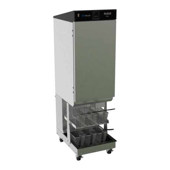
Frozen Food Dispenser
Taylor Model R200
Place this chapter in the Frozen Food
section of the Equipment Manual.
Manufactured exclusively for
®
McDonald's
by
Taylor Company
750 N. Blackhawk Blvd.
Rockton, IL 61072
Phone: (815) 624-8333
Toll Free Number
Outside Illinois:
1 (800) 228-8309
Inside Illinois:
1 (800) 851-5639
Fax: (815) 624-8000
Table of Contents
Introduction ........................................................................................................................................................................... 1
Unpacking and Installation.................................................................................................................................................... 1
Intended Use ........................................................................................................................................................................ 1
Specifications........................................................................................................................................................................ 1
Safety.................................................................................................................................................................................... 2
Equipment Safety ................................................................................................................................................................. 4
Dispenser Assembly ............................................................................................................................................................. 6
Disassembly, Defrost, and Cleaning..................................................................................................................................... 9
Dispenser Startup ................................................................................................................................................................. 9
Operation ............................................................................................................................................................................ 10
User Function Menu Structure ............................................................................................................................................ 13
Configuration (Config) Functions Menu Structure............................................................................................................... 14
Service Functions Menu Structure...................................................................................................................................... 16
Error Detection.................................................................................................................................................................... 20
Troubleshooting .................................................................................................................................................................. 21
Calibrations and Adjustments ............................................................................................................................................. 28
Parts Identification .............................................................................................................................................................. 31
Refrigeration System .......................................................................................................................................................... 42
Disposal of Equipment ........................................................................................................................................................ 47
Electrical Diagram............................................................................................................................................................... 48
Limited Warranty on Equipment.......................................................................................................................................... 49
Limited Warranty on Parts .................................................................................................................................................. 51
Warranty information is contained in this Equipment Manual. Refer to the warranty information listed in the Limited Warranty on
Equipment and Limited Warranty on Parts sections and to the warranty classifications listed in the Parts Identification/Function
section when service is performed on your machine.
It is recommended that the operator take the necessary time to carefully read through the complete warranty information.
Thoroughly understand your warranty protection before you begin operation.
For any questions pertaining to the Taylor warranty, please contact Taylor Company, Rockton, Illinois 61072.
This manual is for the exclusive use of licensees and employees of McDonald's Corporation
©2005 McDonald's Corporation
All Rights Reserved
04/07/20 (Original Publication)
(Updated 04/21/20)
EM SD11
.
The United States of America
089363-MCD
Printed in
Advertisement
Table of Contents

Subscribe to Our Youtube Channel
Related Manuals for Taylor McDonald's R200


Summary of Contents for Taylor McDonald's R200
-
Page 1: Table Of Contents
It is recommended that the operator take the necessary time to carefully read through the complete warranty information. Thoroughly understand your warranty protection before you begin operation. For any questions pertaining to the Taylor warranty, please contact Taylor Company, Rockton, Illinois 61072. This manual is for the exclusive use of licensees and employees of McDonald's Corporation ©2005 McDonald's Corporation... - Page 2 This manual is copyrighted with all rights reserved. Under the copyright laws, this manual may not be copied, in whole or part, without the written consent of Taylor Company. Product names mentioned herein are for identification purposes only, and may be trademarks and/or registered trademarks of their respective...
-
Page 3: Introduction
INTRODUCTION SPECIFICATIONS This manual contains important information on the proper Electrical Requirements: installation, operation, and care of the RAM R200 Frozen Domestic: Food Dispenser. Following the instructions and • 120VAC., 60 Hz, 7.8A, 1 phase procedures in this document will ensure that your International: Dispenser provides years of reliable service. -
Page 4: Safety
• If the supply cord is damaged, it must be replaced by a Taylor service technician in order to avoid a hazard. Failure to follow these instructions may result in electrocution. Contact your local authorized Taylor... - Page 5 The user is responsible for delivering the machine to the appropriate collection facility, as specified by your local code. For additional information regarding applicable local disposal laws, please contact the municipal waste facility and/or local authorized Taylor distributor.
-
Page 6: Equipment Safety
EQUIPMENT SAFETY Important: Turn the power switch OFF and disconnect the dispenser power cord from the wall outlet before cleaning, moving, • or servicing the dispenser. Inspect the dispenser on a regular basis to identify potential problems before they occur. •... - Page 7 Equipment Safety Cont. Figure-3 Label is on the rear access panel and applies to the Figure-1 US Only cabinet insulation and refrigerant. Label is on the rear access panel and applies to the drum CAUTION, RISK OF FIRE KEEP OPEN FLAME FROM motor and accumulator assemblies within the enclosure.
-
Page 8: Dispenser Assembly
DISPENSER ASSEMBLY Note: Before assembling the Dispenser, it is recommended that all parts be cleaned, sanitized, dry, and handled in a sanitary manner. Refer to the Cleaning Procedures (page 9) for more information. Figure-7 Pivot Block Figure-5 Fry Guide Install the fry guide under the cabinet outlet, sliding it onto the mounting rails. - Page 9 Dispenser Assembly Cont. Figure-9 Drum Figure-11 Hopper Assembly Install the drum into the hopper, making sure the square opening in the drum is pointed toward the rear of the hopper. Install the fry diverter in the hopper by sliding the fry diverter tabs into the slots located on the inside hopper wall.
- Page 10 Caution: Do not store hash-browns on the drum below the rack. This can damage the Dispenser. Insert the four rods of the hash-brown rack into the holes in the side of the hopper, then lower the rack onto the fry diverter.
-
Page 11: Disassembly, Defrost, And Cleaning
Dry all components and reassemble the Dispenser DISASSEMBLY, DEFROST, AND CLEANING (page 6). Move Dispenser back into place. Notice: The Dispenser must be accessible from all sides Important! These cleaning instructions are intended as a for routine cleaning and maintenance. A minimum of 1 in. guide. -
Page 12: Operation
The operator panel consists of two groups of controls: the Warning: Pinch Hazard. Personnel should take care not hopper controls and system controls with data display. It to place hands or fingers near the drum inside the hopper is used to make basket load size selections and to while this machine is in operation. - Page 13 forward over the basket sensor. The accumulator Defrost Cabinet Daily: doors will open and close, discharging product into Turn the power switch off, then open the cabinet door to the waiting basket. allow the Dispenser to defrost for 1 hour or until free of frost.
- Page 14 While in Sensor Bypass mode the Dispenser will Low and Empty Hopper Warnings otherwise appear to operate normally, refilling the The RAM R200 Frozen Food Dispenser is equipped with accumulator housings automatically after each dispense a low product sensor. When the product level in the cycle with the selected load of fries.
-
Page 15: User Function Menu Structure
USER FUNCTION MENU STRUCTURE Press the Menu button to find the desired menu, then press the OK button to select the menu. • Use the Up and Down arrow buttons to find the desired function. • Press the OK button to select the desired function. •... -
Page 16: Configuration (Config) Functions Menu Structure
CONFIGURATION (CONFIG) FUNCTIONS MENU STRUCTURE Press the Menu button to find the desired menu then press the OK button to select the menu. • Use the Up and Down arrow buttons to find the desired function. • Press the OK button to select the desired function. •... - Page 17 Function Name Description Step Down (Euro only) Allows the load size step down time periods to be changed. Times shown in minutes. Display shows Large to Medium and Medium to Small load size step down times. Note: Times shown are default times. •...
-
Page 18: Service Functions Menu Structure
SERVICE FUNCTIONS MENU STRUCTURE Press the Menu button to find the desired menu then press the OK button to select the menu. • Use the Up and Down arrow buttons to find the desired function. • Press the OK button to select the desired function. •... - Page 19 Function Name Description Refrig Monitor Displays the present state of the refrigeration Refrig. Cycle Timeout Door:_ system. Out:_ Back:_ Refrigeration Cycle: • “Wait” = In short cycle delay or in Bypass mode. • “Cool” = Initial cooling cycle. • “On” = Normal refrigeration cycle, compressor on. •...
- Page 20 Function Name Description Sensor Monitor Displays the present state of the Basket Sensor_ Basket Sensor. Basket State Weigh cycle “Sensor:_” * indicates sensor is reading a basket present. “Basket State” indicates present basket cycle. • “None” - No basket is present. •...
- Page 21 Function Name Description Test Outputs Turns on and off outputs for diagnostic Output selection Refrig timeout purposes. Out:_ Display shows a flashing Refrig: • Up and Down arrow buttons change the output selection (Refrig, Drum, or Accum). • OK button selects the output. Display will show selected output and a flashing Out: •...
-
Page 22: Error Detection
ERROR DETECTION The main display will read **Error** and state the error which has occurred (e.g. Weighing Issue). If an error does occur, it is normally reset by pushing the OK button. If the failure continues, turn the power switch off and unplug the power cord from the wall outlet. -
Page 23: Troubleshooting
TROUBLESHOOTING The following is a list of errors that may occur, probable causes, and corrective action that may eliminate the problem. If after performing the corrective action the problem persists, contact a service technician. Drum Won’t Turn (Error 1) The controller has detected a CURRENT ERROR FOR THE DRUM MOTOR. The drum motor current draw is monitored by the controller. - Page 24 NVRAM. Contact a service technician for assistance. NV Data Bad and Internal Issue – Contact Taylor Company. † Note: Cooling Slow, Cooling Failed, and Refrig. Error are refrigeration errors. These errors, while requiring corrective action, will not disable the fry dispensing portions of the machine.
- Page 25 Troubleshooting cont. Problem Probable Cause Corrective Action Drum is binding in the hopper. Hopper not installed correctly. Inspect hopper for proper assembly and placement. Drum motor wires are not Check the drum motor connectors are secure at the drum motor secure.
- Page 26 Restrictions to weighing system Verify magnet block is secure and no foreign object is attached to Error 4 movement: In the back of the the magnet. (Weighing Issue) cont. Dispenser. Check behind the accumulator mechanism for any foreign object which may be restricting movement of the assembly. Calibration has been changed Reset Dispenser parameters (defaults) using the Parameter or lost.
- Page 27 Faulty feedback or refrigeration Verify that there are no wiring problems first then replace the Error 7 (Refrigeration Error) relay. feedback (SW3) and refrigeration (SW2) relays. Error must be reset using the Held Errors parameter Faulty controller (rare). Input (from feedback relay SW2) problem on the controller. This in the Clear Functions is not common.
- Page 28 Drive wheel screw or clevis pin Use the Accum parameter in the Test Outputs section of the Accumulator doors not has broken or detached. Service menu to manually operate the accumulator motor and closing doors. If neither door operates or if the doors move only slightly, (one or both accumulator suspect the drive wheel assembly.
- Page 29 Broken or damaged drum. Inspect the drum and drum socket for damage, verify the drum Drum not turning motor shaft turns with the hopper and drum removed. Replace drum. Unable to make a load size Reset Dispenser parameters (defaults) using the Parameter selection, calibration has been function in the Clear Functions section of the Service Menu, then lost.
-
Page 30: Calibrations And Adjustments
A Configuration or Service password can be set and/or CALIBRATIONS AND ADJUSTMENTS changed from both the Configuration Function menu (page 28) or the Service Function menu (page 28) using Scale Calibration the operator panel on the front of the Dispenser. The RAM R200 Frozen Food Dispenser has a scale which weighs and dispenses frozen fries. - Page 31 Small and the current target weight for the small setting Temperature Probe Calibration displayed. Press the Up and Down arrow buttons to The RAM R200 Frozen Food Dispenser uses a single change between Small, Medium, and Large. Press the temperature probe mounted to the wall of the cabinet OK button to select the desired load size.
- Page 32 Adjust the probe temperature to match the actual temperature using the Up arrow to raise the displayed temperature or the Down arrow to lower the displayed temperature. Note: Displayed temperature is adjusted in increments of 0.1°F (0.06°C). Once the displayed temperature matches the thermometer temperature, press the OK button to save the calibration and exit the function.
-
Page 33: Parts Identification
PARTS IDENTIFICATION Dispenser Cabinet Assembly Item Qty. Part # Description 292246 On/Off Switch (15A Circuit Breaker) 295748 Top Cover 294824 Screw Truss head Phillips #10-32x1/2” 295820 Keypad, Membrane 295723 Frame, Operator Panel 213262 Screw Truss Head Slotted 10-32x3/8” R2 00 213140 Washer, Lock, #10 089351 REV... - Page 34 Dispenser Cabinet Exterior (rear view) Item Qty. Part # Description 295821 Display Control PCB On/Off Switch 292246 (15A Circuit Breaker) 293399 Power Cord (Dom.120V) Power Cord (Int. 240V Euro) 294129 295777 Upper Back Panel 295653 Handle, Plastic 294824 Screw, Truss Head, #10-32 x 3/8” 295681 Kit, Bumper, Wall (set of 2) 295779...
- Page 35 Dispenser Cabinet interior (rear view) Item Qty. Part # Description 295821 Display Control PCB On/Off Switch 292246 (15A Circuit Breaker) 295397 Controller PCB Screw, Grounding 202795 293401 Upper Terminal Block 380051 Power Supply, Universal Low Fry Sensor Assembly page 40 293405 Refrigeration Relay 213262...
- Page 36 Interior Cabinet Components Figure-22 Item Part# Description Item Part# Description 294407 Door Switch Housing, Accumulator (Before Serial #s 20FR2001B02418 and 295714 295853 Kit, Probe, Temperature 20PR2001B00197) 295824 P-Clip, Probe Housing, Accumulator (After 295234 Spacer 294416 Serial #s 20FR2001B02417 and 295239 Snap Bushing 20PR2001B00196) 295699...
- Page 37 Weighing System Assembly (Before Serial No. 20FR2001B02418 and 20PR2001B00197) Linkage Assembly 25 26 Figure-23 Item Part# Description Item Part# Description 293322 Weldment, Arm Support 293323 Link, Accumulator, Push 290635 Screw, Shoulder, ¼”x ¼”, #10-24 294009 Kit Acc Motor Includes item 3 & 7 294693 Kit, Drive Wheel 290525...
- Page 38 Weighing System Assembly (After Serial No. 20FR2001B02417 and 20PR2001B00196) Linkage Assembly Figure-24 Item Qty Part# Description Item Qty Part# Description 294350 Accumulator Door, RH 290517 Flange Bearing 3/4" ID x 1" OD x1/2" 294351 Accumulator Door, LH 213356 Retaining Ring, E-Style, 1/2" 294009 Kit Acc Motor Includes item 5 and 6 310196...
- Page 39 Weighing System Assembly (Cont.) (After Serial No. 20FR2001B02417 and 20PR2001B00196) Item Part# Description 213262 Screw SocketHead Cap #10-32 x ⅜" Magnet (Available in Kit 380049 only) 380049 Kit, Block, Magnet Mount (includes Magnet) 213139 Washer, Flat, #10 213136 Screw SocketHead Cap #10-32 x1-¼" 293596 Collar, Accumulator Shaft, White 203257...
- Page 40 Dispensing System Assembly (Before Serial No. 20FR2001B02418 and 20PR2001B00197) Figure-25 Item Part# Description Item Part# Description 295380 Mechanical Panel 294775 Kit, NCWS Base 213559 Screw, Truss HD, 10-32x1/2” SST 213140 Washer, Lock ,Reg Spr, ZP #10.ipt Assembly, Drum Motor w/ Mount Screw, SH Cap, included in 294775 Assembly, Weighing System 213143...
- Page 41 Dispensing System Assembly (After Serial No. 20FR2001B02417 and 20PR2001B00196) Figure-26 Item Part# Description Item Part# Description 295380 Mechanical Panel 294775 Kit, NCWS Base 213559 Screw, Truss HD, 10-32x1/2” SST 213140 Washer, Lock ,Reg Spr, ZP #10.ipt Assembly, Drum Motor w/ Mount Screw, SH Cap, included in 294775 Assembly, Weighing System 213143...
- Page 42 Drum Motor Assembly Figure-27 Item Part# Description Item Part# Description 292546 Motor, Gear, Brushless, 24 VDC 292546 Motor, Gear, Brushless, 24 VDC 202797 Bracket, Mount, Drum motor. 202797 Bracket, Mount, Drum motor. 213140 Washer, Lock, #10 213140 Washer, Lock, #10 Low Fry Sensor Assembly Figure-28 Item...
- Page 43 Controller Board Figure-29 Controller PCB - Part# 295397 Item Description Item Description Power Input +24VDC Accum Home Encoder Basket Sensor Power Input (Ground) High Pressure Switch Relay Drum Motor +24VDC Low Fry Sensor Accum Motor +24VDC Refrigeration Control Probe Drum Motor NCWS Board Accum Motor Display Board...
-
Page 44: Refrigeration System
Required Maintenance REFRIGERATION SYSTEM Daily: General Operation Shut off, clean, defrost, and inspect cabinet (see page 9). The RAM R200 employs a cold wall system. Through the Monthly: refrigeration process, heat is transferred to the Clean and inspect the condenser filter. Replace as condensing unit at the bottom of the cabinet, where it is necessary. - Page 45 Refrigeration System Components Item Qty. Part # Description 294339 Compressor Domestic R404A (120V 1/2HR) 294723 Compressor International R404A (240V 1/2HR ) 295258 Compressor International R290 only (240V 1/2HP) 292501 Filter Drier 295782 Bracket, Support Compressor 295596 Condenser 295707 Screw, Sheet Metal, #8x1/2” 295603 Fan Shroud 295773...
- Page 46 REFRIGERATION SPECIFICATIONS Refrigerant: Model R200: R404A - 2.5 oz. (354 g) Model R200: R290 - 5.15 oz. (146 g) Suction Pressure: 3 psi to 7 psi at -3°F to 3°F (21 kPa to 48 kPa at -19°C to -6°C) Operating Temperature: 5°F to 0°F (-15°C to -18°C) Factory Temperature Set Point = 0°F (-18°C) Factory Differential Set Point: 5°F (3°C) High-Pressure Switch - trips at 425 psi (2,930 kPa)
- Page 47 Refrigeration Circuit - R200 Refrigeration Circuit - R200 Figure-31...
- Page 48 Refrigeration Circuit - R200 (Cont.) Figure-32...
-
Page 49: Disposal Of Equipment
DISPOSAL OF EQUIPMENT Before dismantling the equipment, all food should be removed and the equipment thoroughly cleaned. Dismantling of the equipment must be carried out by qualified personnel in accordance with the manufacturer’s instructions. Dispose of the equipment in accordance with local regulations. It is important to observe the regulations and laws for disposing of environmentally unfriendly materials. -
Page 50: Electrical Diagram
ELECTRICAL DIAGRAM Figure-33... -
Page 51: Limited Warranty On Equipment
Two (2) years In addition, during the two (2) year period commencing on the date of original installation of the Product, Taylor will also provide, through an authorized Taylor distributor or service agency, all service needed to replace the failed defective part at no charge for the service. - Page 52 LEGAL REMEDIES The owner must notify Taylor in writing, by certified or registered letter to the following address, of any defect or complaint with the Product, stating the defect or complaint and a specific request for repair, replacement, or other correction of the Product under warranty, mailed at least thirty (30) days before pursuing any legal rights or remedies.
-
Page 53: Limited Warranty On Parts
Taylor warrants the Parts against failure due to defect in materials or workmanship under normal use and service as follows. All warranty periods begin on the date of original installation of the Part in the Taylor unit. If a Part fails due to defect during the applicable warranty period, Taylor, through an authorized Taylor distributor or service agency, will provide a new or remanufactured Part, at Taylor’s option, to replace the failed defective Part at no charge for the Part. - Page 54 Taylor. 5. Replacement of wear items designated as Class “000” Parts in the Taylor Operator’s Manual, as well as any release sheets and clips for the Product’s upper platen assembly.
- Page 55 LEGAL REMEDIES The owner must notify Taylor in writing, by certified or registered letter to the following address, of any defect or complaint with the Part, stating the defect or complaint and a specific request for repair, replacement, or other correction of the Part under warranty, mailed at least thirty (30) days before pursuing any legal rights or remedies.
- Page 56 089363-MCD...
Need help?
Do you have a question about the McDonald's R200 and is the answer not in the manual?
Questions and answers
Forgot set password, how to reset password
To reset the password for the Taylor McDonald's R200, follow these steps:
1. Press the Menu button until the display reads User Menu.
2. Use the Up or Down arrow buttons to change the function to Calibrate, then press OK.
3. The display will show Set Password and “--------”.
4. Enter a new password using the basket load size buttons and Up/Down arrow buttons.
5. Press OK when finished.
6. The display will now read Repeat Password and “--------”.
7. Re-enter the password sequence and press OK to save and exit.
To cancel a set password, access the Set Password menu and follow the steps to reset it.
This answer is automatically generated