Yaesu FT-2DR Technical Supplement
144/430 mhz dual-band digital transceiver
Hide thumbs
Also See for FT-2DR:
- Operating instructions manual (173 pages) ,
- Operating manual (173 pages) ,
- Instruction manual (80 pages)
Advertisement
Quick Links
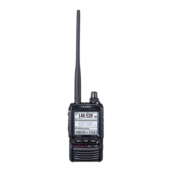
144/430 MHz Dual-Band Digital Transceiver
FT2DR/DE
Introduction
This manual provides the technical information necessary for ser-
vicing the FT2DR/DE 144/430 MHz Dual Band Digital Trans-
ceiver.
Servicing this equipment requires expertise in handing surface-
mount chip components. Attempts by non-qualified persons
to service this equipment may result in permanent damage not
covered by the warranty, and may be illegal in some countries.
Two PCB layout diagrams provided for each double-sided
board in this transceiver. Each side of the board is referred to
by the type of the majority of components installed on that side
("Side A" or "Side B"). In most cases one side has only chip
components, and the other has either a mixture of both chip and
leaded components (trimmers, coils, electrolytic capacitors,
ICs, etc.), or leaded components only.
While we believe the information in this manual to be correct,
YAESU assumes no liability for damage that may occur as a
result of typographical or other errors that may be present. Your
cooperation in pointing out any inconsistencies in the technical
information would be appreciated.
Caution
Risk of explosion if battery is replaced by an incorrect
type. Dispose of used batteries according to the instruc-
tions.
Important Note
This transceiver was assembled using Pb (lead) free
solder, based on the RoHS specification.
Only lead-free solder (Alloy Composition: Sn-3.0Ag-
0.5Cu) should be used for repairs performed on this
apparatus. The solder stated above utilizes the alloy
composition required for compliance with the lead-free
specification, and any solder with the above alloy com-
position may be used.
TECHNICAL SUPPLEMENT
Specifications
Exploded View & Miscellaneous Parts
Block Diagram
Alignment
Board Unit (Schematics, Layouts & Parts)
RF Unit
CNTL Unit
SUB Unit
USB Unit
ENC Unit
MIC Unit
EH060M90C
©2016 YAESU MUSEN CO., LTD.
Contents
Advertisement

Subscribe to Our Youtube Channel
Related Manuals for Yaesu FT-2DR


Summary of Contents for Yaesu FT-2DR
- Page 1 ICs, etc.), or leaded components only. While we believe the information in this manual to be correct, YAESU assumes no liability for damage that may occur as a result of typographical or other errors that may be present. Your cooperation in pointing out any inconsistencies in the technical information would be appreciated.
- Page 2 Specifications General Frequency Range: A Band RX 0.52 - 1.71 MHz (AM Radio) 1.8 - 30 MHz (SW Radio) 30 - 76 MHz (USA version) 30 - 88 MHz (EXP/EU version) 76 - 108 MHz (USA version) 88 - 108 MHz (EXP/EU version) 108 - 137 MHz (Air Band) 137 - 174 MHz (144 MHz HAM) 174 - 222 MHz (VHF Band)
- Page 3 Specifications Transmitter RF Power Output: 5 W (@ 7.2 V DC or EXT DC ) Modulation Type: F1D, F2D, F3E : Variable Reactance modulation F7W: 4 FSK (C4FM) Spurious Emission: USA/EXP version At least 60 dB below (@TX Power HI, L3) At least 50 dB below (@TX Power L2, L1) European version At least 60 dB below (@TX Power HI, L3, L2)
- Page 4 ⑪ RA603400A SHEET(EN514) SEAL(REAR) CNTL-UNIT ⑫ RA1359400 ⑥ ⑪ MASK SHEET ⑥ RA6023800 COVER(REAR) REF. YAESU P/N Description Qty. U9900277 PAN HEAD TAPTITE-B M2X3 #3 3KA ① RA1011800 STUD ⑫ ② ⑫ ③ U07230102 PAN HEAD SCREW M2X3NI #1 RA1084800 WASHER 4.3X2.0...
- Page 5 Block Diagram BLOCK DIAGRAM-1 FT2DR/DE Technical Supplement...
- Page 6 Also, the icy. Also, YAESU must reserve the right to change test equipment must be thoroughly warmed up be- circuits and alignment procedures in the interest of fore beginning.
- Page 7 Alignment Internal System Alignment Routine In the alignment process, each adjustment is se- lected by rotating the DIAL knob. The alignment This uses a programmed routine in the transceiver is performed by: pressing the [ V/M ] key injecting a which simplifies many previously complex discrete signal of the required frequency and level;...
- Page 8 Alignment Tight Squelch Adjustment (TIGH SQL) A-Band 430 MHz Band Adjustment Connect the test equipment as shown in Figure 2: Receiver Sensitivity Adjustment (TUNE DEV) RX Alignment Setup. Connect the test equipment as shown in Figure 2: Rotate the DIAL knob to select the Alignment RX Alignment Setup.
- Page 9 Alignment TX Power (HI) Adjustment (HI POWER) TX Power (L1) Adjustment (L1 POWER) Connect the test equipment as shown in Figure 1: Connect the test equipment as shown in Figure 1: TX Alignment Setup. TX Alignment Setup. Rotate the DIAL knob to select the Alignment ...
- Page 10 Alignment A-Band 50 MHz Band Adjustment CTCSS TX Deviation Adjustment (TONE DEV) Connect the test equipment as shown in Figure 1: Press the [ BAND ] key to select the 50 MHz Ama- TX Alignment Setup. teur band. Rotate the DIAL knob to select the Alignment Menu "TONE DEV".
- Page 11 Alignment A-Band 144 MHz Band Adjustment Tight Squelch Adjustment (TIGH SQL) Connect the test equipment as shown in Figure 2: Press the [ BAND ] key to select the 144 MHz Ama- RX Alignment Setup. teur band. Rotate the DIAL knob to select the Alignment Menu "TIGH SQL".
- Page 12 Alignment Tight Squelch Adjustment (TIGH SQL) TX Power (HI) Adjustment (HI POWER) Connect the test equipment as shown in Figure 2: Connect the test equipment as shown in Figure 1: RX Alignment Setup. TX Alignment Setup. Rotate the DIAL knob to select the Alignment ...
- Page 13 Alignment TX Power (L1) Adjustment (L1 POWER) CTCSS TX Deviation Adjustment (TONE DEV) Connect the test equipment as shown in Figure 1: Connect the test equipment as shown in Figure 1: TX Alignment Setup. TX Alignment Setup. Rotate the DIAL knob to select the Alignment ...
- Page 14 Alignment B-Band 430 MHz Band Adjustment Squelch Threshold Adjustment (THLD SQL) Connect the test equipment as shown in Figure 2: NOTICE: Do not touch the following Alignment RX Alignment Setup. Menus in B-Band 430 MHz Band Adjustment: Rotate the DIAL knob to select the Alignment "PLL REF "...
- Page 15 Alignment B-Band 144 MHz Band Adjustment FM S-Meter Full-Scale Adjustment (S9 LEVEL) Connect the test equipment as shown in Figure 2: NOTICE: Do not touch the following Alignment RX Alignment Setup. Menus in B-Band 144 MHz Band Adjustment: Rotate the DIAL knob to select the Alignment "PLL REF"...
- Page 16 Alignment Squelch Threshold Adjustment (THLD SQL) FM S-Meter Full-Scale Adjustment (S9 LEVEL) Connect the test equipment as shown in Figure 2: Connect the test equipment as shown in Figure 2: RX Alignment Setup. RX Alignment Setup. Rotate the DIAL knob to select the Alignment ...
- Page 17 RF Unit (Lot. 1-2) Circuit Diagram RF-1 FT2DR/DE Technical Supplement...
- Page 18 RF Unit (Lot. 1-2) Parts Layout Side A Side B RF-2 FT2DR/DE Technical Supplement...
- Page 19 RF Unit (Lot. 3) Circuit Diagram RF-3 FT2DR/DE Technical Supplement...
- Page 20 RF Unit (Lot. 3) Parts Layout Side A Side B RF-4 FT2DR/DE Technical Supplement...
- Page 21 RF Unit (Lot. 4-6) Circuit Diagram RF-5 FT2DR/DE Technical Supplement...
- Page 22 RF Unit (Lot. 4-6) Parts Layout Side A Side B RF-6 FT2DR/DE Technical Supplement...
- Page 23 RF Unit (Lot. 7-) Circuit Diagram RF-7 FT2DR/DE Technical Supplement...
- Page 24 RF Unit (Lot. 7-) Parts Layout Side A Side B RF-8 FT2DR/DE Technical Supplement...
- Page 25 RF Unit Parts List DESCRIPTION VALUE TOL. MFR'S DESIG YAESU P/N VERS. LOT SIDE LAY ADR PCB with Components CS2353702 USA: A2U CS2353703 EXP: B3 CS2353704 EU: B2 CS2353705 EU: C2 CS2353706 AUS: H2 C 1001 CHIP CAP. 1.5pF GRM1554C1H1R5BA01D...
- Page 26 RF Unit Parts List DESCRIPTION VALUE TOL. MFR'S DESIG YAESU P/N VERS. LOT SIDE LAY ADR C 1080 CHIP CAP. 22pF GRM1552C1H220JA01D K22178220 C 1081 CHIP CAP. 22pF GRM1552C1H220JA01D K22178220 C 1082 CHIP CAP. 0.022uF GRM155B11C223KA01D K22128806 C 1083 CHIP CAP.
- Page 27 RF Unit Parts List DESCRIPTION VALUE TOL. MFR'S DESIG YAESU P/N VERS. LOT SIDE LAY ADR C 1148 CHIP CAP. 1.5pF GRM1554C1H1R5BA01D K22178288 W/O CE LABEL 2- C 1149 CHIP CAP. GRM1552C1H9R0BA01D K22178296 C 1150 CHIP CAP. 0.01uF GRM155B11E103KA01D K22148834 C 1151 CHIP CAP.
- Page 28 RF Unit Parts List DESCRIPTION VALUE TOL. MFR'S DESIG YAESU P/N VERS. LOT SIDE LAY ADR C 1224 CHIP CAP. 6.3V GRM155B30J105KE18D K22088803 C 1225 CHIP CAP. 6.3V GRM155B30J105KE18D K22088803 C 1226 CHIP TA.CAP. 47uF TMCP0G476MTRF K78060050 C 1228 CHIP CAP.
- Page 29 RF Unit Parts List DESCRIPTION VALUE TOL. MFR'S DESIG YAESU P/N VERS. LOT SIDE LAY ADR C 1307 CHIP CAP. 0.033uF GRM155B11A333KA01D K22108803 C 1308 CHIP CAP. 0.033uF GRM155B11A333KA01D K22108803 C 1308 CHIP CAP. 0.022uF GRM155B11C223KA01D K22128806 C 1310 CHIP CAP.
- Page 30 RF Unit Parts List DESCRIPTION VALUE TOL. MFR'S DESIG YAESU P/N VERS. LOT SIDE LAY ADR C 1383 CHIP CAP. 0.5pF GRM1554C1HR50BA01D K22178285 C 1384 CHIP CAP. 0.001uF GRM155B11H102KA01D K22178809 C 1385 CHIP CAP. 27pF GRM1552C1H270GA01D K22179726 C 1386 CHIP CAP.
- Page 31 RF Unit Parts List DESCRIPTION VALUE TOL. MFR'S DESIG YAESU P/N VERS. LOT SIDE LAY ADR C 1457 CHIP CAP. 0.001uF GRM155B11H102KA01D K22178809 C 1458 CHIP CAP. 10pF GRM1552C1H100BA01D K22178297 C 1458 CHIP CAP. 9.5pF GRM1552C1H9R5BA01D K22179730 C 1459 CHIP CAP.
- Page 32 RF Unit Parts List DESCRIPTION VALUE TOL. MFR'S DESIG YAESU P/N VERS. LOT SIDE LAY ADR C 1537 CHIP CAP. 6.3V GRM155B30J105KE18D K22088803 C 1538 CHIP CAP. 6.3V GRM155B30J105KE18D K22088803 C 1541 CHIP CAP. 4.7uF AMK105BJ475MV-F K22068801 C 1544 CHIP CAP.
- Page 33 RF Unit Parts List DESCRIPTION VALUE TOL. MFR'S DESIG YAESU P/N VERS. LOT SIDE LAY ADR D 1046 DIODE 1SV281(TPH3.F) G2070620 D 1047 DIODE 1SV281(TPH3.F) G2070620 D 1048 DIODE 1SV325(TPH3.F) G2070848 D 1049 DIODE 1SV325(TPH3.F) G2070848 D 1050 DIODE 1SV325(TPH3.F)
- Page 34 RF Unit Parts List DESCRIPTION VALUE TOL. MFR'S DESIG YAESU P/N VERS. LOT SIDE LAY ADR J 1003 CONTACT IPS-4099T-01Y900 S5000402 J 1004 CONTACT IPS-4099T-01Y900 S5000402 J 1005 CONTACT IPS-4099T-01Y900 S5000402 J 1006 CONTACT IPS-4099T-01Y900 S5000402 L 1001 M.RFC 0.01uH...
- Page 35 RF Unit Parts List DESCRIPTION VALUE TOL. MFR'S DESIG YAESU P/N VERS. LOT SIDE LAY ADR L 1074 M.RFC 2.2uH LK1005 2R2K-T L1691716 L 1075 M.RFC LK1005 1R0K-T L1691715 L 1076 COIL E2 0.25-1.85-8.5T-L L0022576 L 1077 COIL E2 0.28-1.0-4.5T-R...
- Page 36 RF Unit Parts List DESCRIPTION VALUE TOL. MFR'S DESIG YAESU P/N VERS. LOT SIDE LAY ADR Q 1024 TRANSISTOR 2SC5646A(TAPE) G3356468 Q 1025 TRANSISTOR 2SC5646A(TAPE) G3356468 Q 1026 MB15A01PFV1-G-BND-EFE1 G1092545 Q 1027 TRANSISTOR DTC143ZM G3070400 Q 1028 TRANSISTOR DTC143ZM G3070400...
- Page 37 RF Unit Parts List DESCRIPTION VALUE TOL. MFR'S DESIG YAESU P/N VERS. LOT SIDE LAY ADR Q 1098 TRANSISTOR 2SA2029 T2L Q/R G3120298 Q 1099 TRANSISTOR EMB3 T2R G3070303 Q 1100 TRANSISTOR DTC144EM T2L G3070309 Q 1101 TRANSISTOR EMG2 T2R...
- Page 38 RF Unit Parts List DESCRIPTION VALUE TOL. MFR'S DESIG YAESU P/N VERS. LOT SIDE LAY ADR R 1052 CHIP RES. 1/16W RMC1/16S 103JTH J24189037 R 1053 CHIP RES. 1/16W RMC1/16S 221JTH J24189017 R 1054 CHIP RES. 1/16W RMC1/16S 681JTH J24189023 R 1055 CHIP RES.
- Page 39 RF Unit Parts List DESCRIPTION VALUE TOL. MFR'S DESIG YAESU P/N VERS. LOT SIDE LAY ADR R 1119 CHIP RES. 1/16W RMC1/16S 183JTH J24189040 R 1120 CHIP RES. 1/16W 0.5% RR0510P-471-D J24189111 R 1121 CHIP RES. 1/16W 0.5% RR0510P-103-D J24189143 R 1122 CHIP RES.
- Page 40 RF Unit Parts List DESCRIPTION VALUE TOL. MFR'S DESIG YAESU P/N VERS. LOT SIDE LAY ADR R 1193 CHIP RES. 1/16W RMC1/16S 101JTH J24189013 R 1194 CHIP RES. 1/16W RMC1/16S 105JTH J24189061 R 1195 CHIP RES. 1/16W RMC1/16S 471JTH J24189021 R 1196 CHIP RES.
- Page 41 RF Unit Parts List DESCRIPTION VALUE TOL. MFR'S DESIG YAESU P/N VERS. LOT SIDE LAY ADR R 1267 CHIP RES. 1/16W RMC1/16S 102JTH J24189025 R 1268 CHIP RES. 1/16W RMC1/16S 153JTH J24189039 R 1269 CHIP RES. 330k 1/16W RMC1/16S 334JTH...
- Page 42 RF Unit Parts List DESCRIPTION VALUE TOL. MFR'S DESIG YAESU P/N VERS. LOT SIDE LAY ADR R 1337 CHIP RES. 1/16W RMC1/16S 103JTH J24189037 R 1338 CHIP RES. 4.7k 1/16W RMC1/16S 472JTH J24189033 R 1339 CHIP RES. 1/16W RMC1/16S 103JTH...
- Page 43 CNTL Unit (Lot. 1-2) Circuit Diagram FT2DR/DE Technical Supplement CNTL-1...
- Page 44 CNTL Unit (Lot. 1-2) Parts Layout Side A Side B FT2DR/DE Technical Supplement CNTL-2...
- Page 45 CNTL Unit (Lot. 3-6) Circuit Diagram FT2DR/DE Technical Supplement CNTL-3...
- Page 46 CNTL Unit (Lot. 3-6) Parts Layout Side A Side B FT2DR/DE Technical Supplement CNTL-4...
- Page 47 CNTL Unit (Lot. 7-) Circuit Diagram FT2DR/DE Technical Supplement CNTL-5...
- Page 48 CNTL Unit (Lot. 7-) Parts Layout Side A Side B FT2DR/DE Technical Supplement CNTL-6...
- Page 49 C 2112 CHIP CAP. 0.001uF GRM155B11H102KA01D K22178809 C 2113 CHIP CAP. 0.001uF GRM155B11H102KA01D K22178809 C 2114 CHIP CAP. 22uF 6.3V GRM188R60J226MEA0D K22084807 C 2116 CHIP CAP. 0.001uF GRM155B11H102KA01D K22178809 ø Please contact YAESU when replacing the CNTL-UNIT. CNTL-7 FT2DR/DE Technical Supplement...
- Page 50 CNTL Unit Parts List DESCRIPTION VALUE TOL. MFR'S DESIG YAESU P/N VERS. LOT SIDE LAY ADR C 2118 CHIP CAP. 0.22uF GRM155B31A224KE18D K22108808 C 2119 CHIP TA.CAP. 100uF TMCMC1C107MTRF K78120098 C 2120 CHIP CAP. 0.001uF GRM155B11H102KA01D K22178809 C 2121 CHIP CAP.
- Page 51 CNTL Unit Parts List DESCRIPTION VALUE TOL. MFR'S DESIG YAESU P/N VERS. LOT SIDE LAY ADR C 2219 CHIP CAP. 0.001uF GRM155B11H102KA01D K22178809 C 2220 CHIP CAP. 0.001uF GRM155B11H102KA01D K22178809 C 2221 CHIP CAP. 0.1uF GRM155B11A104KA01D K22108802 D 2001 DIODE...
- Page 52 RMC1/16S 101JTH J24189013 R 2011 CHIP RES. 390k 1/16W RMC1/16S 394JTH J24189056 R 2012 CHIP RES. 1/16W 0.5% RR0510P-102-D J24189119 R 2013 CHIP RES. 1/16W 0.5% RR0510P-102-D J24189119 ø Please Contact YAESU when replacing this part. CNTL-10 FT2DR/DE Technical Supplement...
- Page 53 CNTL Unit Parts List DESCRIPTION VALUE TOL. MFR'S DESIG YAESU P/N VERS. LOT SIDE LAY ADR R 2018 CHIP RES. 1/16W RMC1/16S 473JTH J24189045 R 2021 CHIP RES. 1/16W RMC1/16S 103JTH J24189037 R 2023 CHIP RES. 1/16W RMC1/16S 223JTH J24189041 R 2029 CHIP RES.
- Page 54 CNTL Unit Parts List DESCRIPTION VALUE TOL. MFR'S DESIG YAESU P/N VERS. LOT SIDE LAY ADR R 2137 CHIP RES. 1/16W RMC1/16S 473JTH J24189045 R 2138 CHIP RES. 1/16W RMC1/16S 105JTH J24189061 R 2139 CHIP RES. 4.7k 1/16W RMC1/16S 472JTH...
- Page 55 CNTL Unit Parts List DESCRIPTION VALUE TOL. MFR'S DESIG YAESU P/N VERS. LOT SIDE LAY ADR R 2235 CHIP RES. 1/16W RMC1/16S 103JTH J24189037 R 2243 CHIP RES. 1/16W RMC1/16S 103JTH J24189037 R 2244 CHIP RES. 1/16W RMC1/16S 473JTH J24189045 R 2245 CHIP RES.
- Page 56 CNTL Unit Parts List DESCRIPTION VALUE TOL. MFR'S DESIG YAESU P/N VERS. LOT SIDE LAY ADR X 2004 XTAL NX3225SA 16MHz 16.000MHZ H0103415 X 2005 XTAL NX3215SA 32.768kHz 32.768KHZ 7P H0103399 X 2006 TCXO 18.432MHz TTS18NSE-A11 18.432M H9501220 CNTL-14 FT2DR/DE Technical Supplement...
- Page 57 SUB Unit Circuit Diagram FT2DR/DE Technical Supplement SUB-1...
- Page 58 SUB Unit Parts Layout Side A Side B FT2DR/DE Technical Supplement SUB-2...
- Page 59 SUB Unit Parts List DESCRIPTION VALUE TOL. MFR'S DESIG YAESU P/N VERS. LOT SIDE LAY ADR C 3001 CHIP CAP. 6.3V GRM155B30J105KE18D K22088803 C 3002 CHIP CAP. 0.0047uF GRM155B11H472KA01D K22178838 C 3003 CHIP CAP. 0.0047uF GRM155B11H472KA01D K22178838 C 3004 CHIP CAP.
- Page 60 SUB Unit Parts List DESCRIPTION VALUE TOL. MFR'S DESIG YAESU P/N VERS. LOT SIDE LAY ADR Q 3008 TRANSISTOR DTC144EM T2L G3070309 Q 3009 TRANSISTOR DTC144TM T2L G3070401 Q 3010 TRANSISTOR DTC144EM T2L G3070309 Q 3011 TRANSISTOR DTC144TM T2L G3070401...
- Page 61 SUB Unit Parts List DESCRIPTION VALUE TOL. MFR'S DESIG YAESU P/N VERS. LOT SIDE LAY ADR R 3063 CHIP RES. 4.7k 1/16W RMC1/16S 472JTH J24189033 R 3064 CHIP RES. 1.5k 1/16W RMC1/16S 152JTH J24189027 R 3065 CHIP RES. 1/16W RMC1/16S 471JTH...
- Page 62 USB Unit Circuit Diagram Parts Layout Side A Side B Parts List DESCRIPTION VALUE TOL. MFR'S DESIG YAESU P/N VERS. LOT SIDE LAY ADR J 4001 CONNECTOR AXJ436540G-M P1091456 USB-1 FT2DR/DE Technical Supplement...
- Page 63 ENC Unit Circuit Diagram Parts Layout Side A Side B ENC-1 FT2DR/DE Technical Supplement...
- Page 64 MIC Unit Parts Layout Parts List DESCRIPTION VALUE TOL. MFR'S DESIG YAESU P/N VERS. LOT SIDE LAY ADR PCB withComponents CS2394101 C 0001 CHIP CAP. 0.001uF GRM188B11H102KA01D K22174821 MC0001 MICROPHONE ELEMENT PFO-T6022P-1.5 M3290060 ENC-2 FT2DR/DE Technical Supplement...
- Page 65 Copyright 2016 YAESU MUSEN CO., LTD. All rights reserved No portion of this manual may be reproduced without the permission of YAESU MUSEN CO., LTD.
Need help?
Do you have a question about the FT-2DR and is the answer not in the manual?
Questions and answers