Table of Contents
Advertisement
MANUAL Introduction
The manual is written in sequence for the beginner. If you are a first time user spend some time
working through it and understanding where and how the information are put together so that it will
be easy to find what you are looking for. If you are an expert, use this guide to jump to the right
chapter. Is has a lot of information and may be frustrating to find the answers if you don't know
where to look.
NB! Make sure you have read the Terms and Conditions on the website
www.spitronics.co.za
before you install this ECU. By installing the ECU you automatically agree to these conditions.
1.TITAN Introduction
This chapter discusses the TITAN ECU as a product, how it is designed, and how it operates in
general.
2.Safety Precautions
This chapter discusses the all the safety precaution to the user and the product. Very important
to read!!
3.Requirements
This chapter discusses the requirements for the ECU to run on the engine and the PC
specifications to communicate with the ECU.
4.Hardware Installation
This chapter discusses the how to do the wiring and physical installation of the ECU. Be sure to
read the precautions during this faze!!
5.Software Installation
This chapter discusses the how to install the software and drivers to connect to the ECU.
6.Software Operation and Setup
This chapter discusses the operation of the tuning software and how to set the parameters up for
each specific engine.
7.Other Setup duties and Information
This chapter discusses other settings and equipment setup around the ECU.
8.Startup Procedure
This chapter discusses the basic sequence of actions to prevent damage during the startup faze.
9.Tuning Principles
This chapter discusses tuning information after the engine has been started. This is to enhance
performance and economy and correct operation of the ECU.
10.Fault Finding
This chapter discusses the symptoms and remedies of known faults.
11.Specifications
This is a list of specifications for the TITAN ECU.
12.Firmware Programmer
This chapter discusses how to upgrade or change the TITAN ECU Firmware.
Advertisement
Table of Contents

Related Manuals for Spitronics TITAN Standard

Summary of Contents for Spitronics TITAN Standard
- Page 1 Is has a lot of information and may be frustrating to find the answers if you don’t know where to look. NB! Make sure you have read the Terms and Conditions on the website www.spitronics.co.za before you install this ECU. By installing the ECU you automatically agree to these conditions. 1.TITAN Introduction This chapter discusses the TITAN ECU as a product, how it is designed, and how it operates in general.
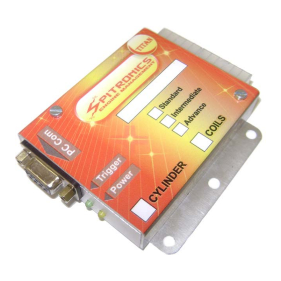
- Page 2 TITAN ECU Welcome Congratulations on your purchase of the TITAN Engine Control Unit (ECU). We are sure that you will be satisfied with this robust, compact and user friendly controller, which was designed to meet today’s requirements. This ECU was developed around the people involved with Management Computers.
- Page 3 The different models are as follows: TITAN Standard This is the most basic and cost effective form of the ECU. It is a single channel trigger, (Magnetic or Hall input,) one coil output and two batch injector outputs. The injectors are pulsed 180°...
- Page 4 injectors and coils. Sensor inputs can be 60-2, 36-1, 24T+TDC and just about any kind of hall or magnetic setup on the engine. Coil driver outputs can be for single or wasted spark coils. It can do idle control and launch control is standard. All wiring harnesses use screened cables for neatness of installation and to prevent interference from other electronics or electromagnetic pulses, which may otherwise cause erratic behavior of the ECU.
- Page 5 that goes up, down and up again. Impossible with weights! Also easy nowadays is to install a turbo. Now you have to retard the time under boost. Easy! So please do a little homework and save yourself a lot of hassles and money of course. And please read the manuals! Features •...
- Page 6 scared of the terms and the electronics. If you worked on a program like Windows Excel, you should be able to breeze through this. On a carburetor you had a low pressure fuel pump which only job was to fill the bowl with the help of a needle and seat.
-
Page 7: Safety Precautions
the engine, a vacuum will form in the ventury sucking harder on the idle jets and main jets and so make the cranking mixture rich enough for starting. The moment the engine starts, a vacuum canister will force the choke butterfly open slightly causing air to flow freely through the ventury. As the engine heats up the choke butterfly will open completely also releasing the bottom throttle to its normal position. -
Page 8: Operator Safety
ECU. It will hang the ECU and damage coils or drivers. This does not apply to Spitronics USB converters. • Make sure that relay pin numbers of the relay correspond with the drawing. A different relay may damage the ECU. -
Page 9: Engine Requirements
• Ensure a proper earth between battery negative and chassis and also between battery negative and the engine. Do not earth the engine on the body or the body on the engine. • Do not put cutout switches from coil negative to ground as this may burn the coil permanently. -
Page 10: Hardware Installation
This software is developed under the latest Delphi environment. It requires a lot of processing speed and may not run on older computers. 4. Hardware Installation 4.1 Compatibility to the old EMU series 4.2 Harness Selection 4.3 Jumper Selection 4.4 Installing Procedure of the ECU 4.5 Injectors 4.6 Sensors 4.7 Idle Control... -
Page 11: Jumper Selection
4.3 Jumper Selection The TITAN ECU has standard harnesses for all engine configurations. The two basic groups of sensors require 12V for Hall and Optic sensors and 5V for Magnetic sensors. This selection between the supply voltages is done by jumper settings. There is also a stronger pull-up resistor required for the hall or Optic sensors and they are also selected with the Jumpers. - Page 12 • Ensure that the enclosure of the ECU is grounded with at least two metal screws onto the metal body of the car. If the ECU is not bolted directly onto an earthed metal surface, you MUST make sure that you run a 4mm ground wire to one of the ECU’s bolt holes, otherwise your ECU will not power up and you will damage the MAP sensor permanently.
- Page 13 4.5.5 Throttle Body Injection With this method, injectors are situated at the throttle body. Spitronics do a Weber 2 Injector and a Holley 4 Injector conversion. With these conversions injectors is situated on the top of the butterfly.
- Page 14 ensure the correct injectors are on the correct drivers. On the CD are drawings for this injector wiring. 4.5.6 Micro Fueling Injector The ECU allows for the use of dual injectors per cylinder as explained in the Setup. Wiring is done in two ways which differ also with the firmware loaded into the ECU.
- Page 15 sensor, it means that the red wire of your meter is on the positive of the sensor. If it is the other way round, then the black wire is on the positive of the sensor. 4.6.2 Hall & Optic sensors 1.
-
Page 16: Throttle Position Sensor
• Remember this is a guideline to black box testing and not a failsafe operation. Note point 4 above and rather consult the specifications from the manufacturer or vehicle diagrams. 4.6.3 Throttle Position Sensor • The TPS must operate through the whole range of the throttle movement to ensure that the ECU can measure the whole of the movement. -
Page 17: Map Sensor
4 Wire Lamda Sensor Wiring Black Lamda Lamda From ECU Blue Grey White Fuse Box 4 Wire Lambda White Testing a Lambda Sensor for the Correct Pin-Outs Test the resistance with an Ohm Meter between 2 pins at a time. The element normally has the same colors and has a resistance of 6 to 12 Ohm. -
Page 18: Idle Control
MPX4250AP - 2.5 Bar MPX4115AP - 1 Bar (number view) MAP Sensor SPITRONICS 1 or 2.5 BAR ENGINE MANAGMENT • Then there is also a surface mount sensor which is 5V and comes in 1Bar and 3Bar. These ones will be mounted on the unit’s PCB or a separate housing. No further info available at this time. -
Page 19: Throttle Adjustment
Warning! Make sure that the Diode stipe is on the right side as damage will ocur if connected wrong. Ign+ Controler Diode 1N4007 Green Yellow This Diode will prevent current feedback from the Idle vave which will keep the EMU running when switched off Yellow GP Output 1 Green GP Output 2 To Fan etc... -
Page 20: Launch Control
4.8 Launch Control Launch control is standard software on all 3 ECU boxes. The buttons however can be bought optional or made up by you. The launch limits consist of an additional rev limiter which is lower than the engine protection limiter. It will retard the timing to a value near TDC and will enrich the fuel mixture by a set percentage. -
Page 21: Additional Wiring
From GP1 or GP2 4Cyl High Imp 15 Ohm 4Cyl High Imp 15 Ohm Mosfet Switch Inj 2 Black Inj1 White Secondary Injectors Primary Injectors From GP1 or GP2 4Cyl Low Imp 3 Ohm 4Cyl Low Imp 3 Ohm Mosfet Switch Inj 2 Black NB! Connect the Positive to the Inj1 White... - Page 22 To Revcounter RPM Output Green Resistor Option 1 1K Ohm Electronic 0.25W revcounters From Ignition + Coil Negative Rev Counters may not work with the above connection because they require a spike rather than a ground signal. In this case the rev counter must be connected to coil negative. Then you will have to calibrate the rev counter or try the circuit below.
- Page 23 connections in the harness to ease with installation. The pin-outs are just for reference. Please follow the labels on the wiring harness when connecting up your new ECU. All wires are grouped gether for ease of installation. Harness Connector Pin View Figure shows a view of the 12pin Female Plug on the ECU harness.
- Page 24 Injector 2 - RPM Trigger Output to ground Gen Purpose Out 2 - 4.11 Coil Selection It is important to know which coil is on the engine as a faulty setting here may destroy the ECU driver or coil. Always start the ECU with a disconnected 10Way connecter till you set the Trigger Level Output to the correct setting.
-
Page 25: Setting Timing
Coil B Coil A From Fuse Box From Fuse Box Trigger Trigger 220 Ohm Pull-Up Resistor From EMU - Coils 4.12 Setting Timing 4.12.1 Setting Distributor Timing and Rotor Fazing This setup for distributors with Rotors requires 2 settings. One is to align the rotor with actual crank degrees and the other is to align the software with the sensor timing. - Page 26 Distributor To Plug From Coil Rotor Distributor To Plug 25°BTDC From Coil Rotor Distributor To Plug From Coil Rotor Rotate the engine so that the static timing mark is at 25° BTDC. If the marks does not go that far take the 12°...
- Page 27 Software Sensor Timing This setting, Timing Sensor °BTDC, will tell the software at what degrees the sensor is situated. The ECU will calculate from this position where to advance or retard the timing to ensure that the Map Timing is accurate with the actual timing on the engine. In the PC software you must enter the Timing Sensor °BTDC for the specific distributor.
- Page 28 included) multiply by 2 divide by the no of cylinders. This means that a 60-2 gear for a 6 cylinder engine is 60*2/6=20. If the teeth between the sensor and slot is ex 25 then you set it at 5 (teeth – pitch) and change the coil wires in sequence.
- Page 29 4.12.3 Setting Toyota 24Pulse + TDC Timing This is a standard setup for most Toyota engines. There is a 24 teeth gear and a TDC reference signal. If it has a Rotor and single coil, first do rotor fazing as described above under Rotor Fazing. Then put the engine on the TDC mark.
-
Page 30: Fuel Supply
24 Tooth Gear TDC Pulse Gear 4.12.4 Setting Nissan Optic Slots Timing This is a standard setup for most Nissan engines. There is a metal disk with 360 fine slots and large slots equaling the number of cylinders. It has two optical sensors. The ECU uses only the large slots. -
Page 31: Pc Software Installation
When you start the software for the first time, it will prompt you to accept the Terms & Conditions as laid out by Spitronics Micro Ignitions cc. Read these conditions carefully and if you agree you may except the terms and continue to work on the ECU. If you press cancel the program will close. -
Page 32: Button Description
When using other than Spitronics cables, you have to break out pin 1,4,6,7,8 & 9 as they are used for other inputs and outputs such as for programming the ECU as well as the launch control buttons. See drawing. - Page 33 Connect the optional serial cable or RS232 converter cable to your laptop or PC and to the ECU. (Remember to break out pins 1,4,6,7,8 & 9 if it is not a Spitronics USB converter) Switch the ignition on and check if the yellow LED is on. Open the ECU PC software. If the ECU is connected the PC software will pick it up on the Com port automatically and connect to it.
- Page 34 for tuning. When the user changes the maps, the processor will immediately start working with the new data changed in the RAM. Laptop TITAN ECU RS232 Write to ECU button Changes FLASH Tempory Tempory Permanent Working Working Storage Read from Memory Memory Memory...
- Page 35 6.4.3 Loading a Map from the hard disk onto an ECU First connect to the ECU. Then press the Open file button. Then press the Write to ECU button. The data will now be written into the ECU flash memory. Note that the serial number is not written in the process although for this session the serial number is the same as the Map serial number.
- Page 36 6.5 Selecting Different Pages in the Software 6.6 Start (F1) 6.7 Setup (F2) 6.8 Maps (F3) 6.9 Logger (F4) 6.10 Manual (F5) Press on any of these buttons to activate the different pages in the software. By pressing the alt button you will see the hot keys for these buttons. The function keys are easier to press during driving.
-
Page 37: Version Numbers
6.6.1 Version Numbers The designer reserve the right to do changes to existing designs and harnesses as he keeps on developing software and hardware. The market change all the time as new ideas submerges. The ECU has a version number system so that the user knows which drawings, and also which Tuning MAP goes with which ECU firmware. - Page 38 ECU must be programmed with Ver. 2.1 PC software. Older version software than Ver.1.13 will open and change parameters but will not be able to save the data. From Ver.1.14 software will also warn if incompatible ECU firmware is used. The alphabetic number will indicate later version changes in the ECU or PC but does not change the protocol of Ver.2.1 software.
-
Page 39: Map Information
Click on the setup tab to get information on the configuration of your engine. Most parameters are being preset before the ECU has been shipped. Ensure that these settings are correct as some may damage components on your engine or the ECU itself. Click on of these icons to adjust different settings in the setup page. -
Page 40: Engine Configuration
6.7.1.2 Engine Configuration Cylinders – 2,3,4,5,6,8 or 12 cylinders can be typed in this block, depending on the engine specific ECU. Most ECU firmware will over-write this block at start-up. Map sensor – adjusts the map sensor range that you use e.g. 1bar = 10, 2.5bar=25. If you have a 2.5 bar sensor but you only use 0.5 bar boost, enter a value of 15 for 1.5 bar and calibrate the MAP sensor so that you are able to make full use of the complete vacuum range for correction adjustment. - Page 41 Example: RPM for a shift light, RPM or TPS to switch nitrous on, water temp to control a fan relay. Also set the appropriate values in the min and max blocks e.g. shift light – min 5000 max 8000. The light will switch on at 5100 RPM’s and switch off at 8100 RPM’s. If the min value is smaller than the max value, the relay will switch on between the limits.
-
Page 42: Timing Configuration
6.7.2.1 Timing Configuration Maximum Timing – this is the max timing allowed by all the timing maps combined. Coil time – 2ms to 5ms. This is the maximum charge time that the user can select. The ECU will vary the charge time automatically according to vacuum load from 2ms to the user selected value. If the ECU heats up it is a result of too large charge times. - Page 43 6.7.3 Fuel Setup (Alt 3) 6.7.3.1 Fuel Configuration Start enrichment – Set a value in milliseconds here for start enrichment. This enrichment is added to the calculated fuel when the engine is started. It will then be phased out in a certain RPM’s.
-
Page 44: Accelerator Pump
the throttle position in conjunction with RPM is used to calculate engine vacuum. It is a bit more difficult to tune but can be done. A disadvantage is that it cannot compensate for sea level correction. The TPS is calibrated as normal to allow the tuner to make use of the full graph. Then the TPS signal is projected in the Map sensor’s graphs. -
Page 45: Active Sensors
The RPM correction maps are divided in four groups of map values. A low, cruise, high cruise and high map. The Low map – this is the map for low throttle cruising or idle The Cruise map – this is the map for normal cruising The High Cruise map –... - Page 46 Then click on the Write to ECU button. When you switch the ECU off and on again, the TPS bar should indicate 0% when pedal is released and 100% when pedal is pressed. Remember that idle control will only take place when the TPS is less than the value set in the Fuel cutoff TPS block.
- Page 47 6.7.4.3 Idle Control Before adjusting the idle control you must select which type of valve is on the engine. Remember if it is a stepper control (4 to 6 wire), then you require the external electronic driver. Also remember to set the relevant GP outputs to Idle Control. Idle control can be used for two-wire and non spring loaded three-wire valves.
- Page 48 6.7.4.4 Lambda Configuration This block is used to set control parameters for the ECU to use the lambda signal to adjust fuel enrichment while driving. Note that lambda sensor correction will only operate when the engine temperature is above 60°C. The target volts are the set point for the ECU to achieve during fuel correction.
- Page 49 6.7.5.1 Launch Control The launce control is activated by a push button on the dashboard to activate and a button on the clutch pedal if automatic latch up operation is required. Once the RPM’s go over 4000 then these 3 parameters will take effect. The new rev limiter will cut the fuel and spark. The timing will be retarded and the fuel mixture will be enriched.
- Page 50 If you are not sure on the injector sizes, first tune the engine with only the primary injectors. Choose a certain RPM and load on manifold pressure and set the Vacuum Limit field higher so that the secondary injectors stay off. Now start with 50% value in the Compensation % field. Reduce the Vacuum Limit so that the secondary injectors start operating.
-
Page 51: Vacuum Gauge
6.7.6.1 RPM Gauge RPM - This is the current engine revolutions. 6.7.6.2 Time Gauge TIMING - This is the calculated timing of all the timing maps and will be the same as seen on the timing light. 6.7.6.3 Vacuum Gauge VACUUM - This is the vacuum value from the MAP sensor. - Page 52 6.7.6.5 Water Air & Battery Indicator Bar These 3 bars will indicate water and air temperatures and also the battery voltage as it is supplied to the ECU. 6.7.6.6 Injector Time and % Indicator Bar This ms bar indicates the time in milliseconds that the injectors are opened. For a 4-stroke engine this is measured over 2 revolutions and for a 2-stroke engine it is measured over 1 revolution.
- Page 53 6.8.4 Correction Maps (Alt 4) 6.8.5 Data Logger (F4) 6.8.6 Manual (F5) Click on the Maps tab to get information on the tuning maps of your engine. Startup Maps are being preset before the ECU has been shipped. These maps may require to be adjusted to suit your engine.
- Page 54 You can click on the mouse button and adjust with a mouse by simply dragging the graph. You may switch the real-time tracking on so that the green adjustment bar will follow the blue active bar. Then you will adjust the value where the RPM’s is at the time. Notice the graph below 400 RPM’s is set to the cranking timing.
- Page 55 6.8.2.1 Main Jet Setting The base line fuel is calculated by the ECU and not mapped in a look-up table like matrix systems. Calculations alone cannot compensate for all deviations in and engine. The ECU uses correction graphs to compensate for all kinds of deviations. The Main Jet adjusts global fuel supply to the injectors much like the main jet in a carburetor would.
- Page 56 6.8.2.2 Idle Jet Setting The Idle jet setting adjusts global idling fuel supply to the injectors much like the idle jet in a carburetor would. Calculations at idle uses a part of the main jet setting, and gradually fade away as the vacuum signal decreases under load.
- Page 57 When the Pink vacuum bar moves between these zones, a different graph is selected on the Fuel RPM Map below. You can click on the mouse button and adjust with a mouse by simply dragging the graph. You may switch the real-time tracking on so that the green adjustment bar will follow the blue active bar.
- Page 58 These two graphs will manipulate the target voltage with a certain percentage. As we use a narrow band sensor it is not recommended using this feature. It is ideal for a wideband sensor with a linear voltage output. Then you can activate the sensor to control over all load conditions. 6.8.4 Correction Maps (Alt 4) 6.8.4.1 Temperature Correction map This map is to set the water temperature correction mostly for cold starting.
- Page 59 the accelerator in. If there is a flat spot, the mix is too lean. Always adjust the minimum mix to just eliminate the flat spot effect. The yellow bar indicates actual water temperature of engine 6.8.4.2 Air Temperature Correction map This map is used to set the air temperature compensation for Fuel and Timing.
- Page 60 First select the appropriate signal you would like to record by checking the box next to it. Check the Interval block to decide the resolution of the samples. For quick real-time logging you can log the data on the map by pressing the buttons.
- Page 61 Alternately you can record the data to a file by pressing the button. Select a filename which the data must be saved in. Once a recording file is active or a Log file is opened, this bar will be displayed on all the map pages.
-
Page 62: Jump Starting The Engine
The Log file can be opened and replayed at a later stage by pressing the button. This feature will also allow the file to be mailed to the tuner for remote fault finding. To do adjustments remotely firs load in the engine map and then open the file. Play it back and do adjustment. -
Page 63: Start-Up Procedure
1,4,6,7,8 &9 are broken out of the communications connector if you are not using a Spitronics USB Converter cable. 5. Now switch the Ignition off and connect the Laptop to the unit. Switch it on again. Start the PC software and connect to the ECU. The engine data like the water temp sensor should be displayed. - Page 64 11. You may now crank the engine without the 10 way connector. Check that the Green LED flashes. Also look at the RPM signal on the timing map. It should show 200 to 300 rpm constant. If it shows erratic and run wild, do not try to start. First find the fault. It must be constant.
- Page 65 9.1 Fuel Settings for Starting the Engine The ECU has n few sequences how to start the engine. An engine requires an initial prime pulse of fuel to start the moment the engine is cranked, then a richer mixture during cranking. Once it started, it also requires a certain amount of richer mixture than idling to get it going till normal idle settings can take over.
- Page 66 To start the engine the first time, use the main jet slider. Start with a low value and increase it until the engine start. If it starts adjust the main jet so that it can idle. Always go for the leanest position (bottom) on the slider not to over fuel the engine.
- Page 67 decreased. Increase the idle jet 4 to 6 pulses higher when the engine is lean. The lambda should now read on the rich side. Too rich will also cause the engine to lose RPM’s or the vacuum bar to move to the right. Increase the mixture to see where is the furthest point to the right on the lambda bar to determine the sensor maximum.
- Page 68 9.4.3 Setting the Idle in Drive for an Automatic Gearbox Put the gearbox in drive. The vacuum bar should move a bit to the right. This is due to load on the engine by the torque converter. Now adjust the vacuum map graph around the vacuum bar till it idles at the right mix again.
-
Page 69: Battery Voltage Compensation
The TPS % must be below this value. Set a value small enough to activate when the throttle is released. If no TPS are installed, uncheck the TPS under active sensors. Then this feature will only work with the next 2 functions. The vacuum signal must be lower than this value to activate the feature. -
Page 70: Fault Finding
subtract cranking fuel for startup. The main problem is wiring. If positive wires supply different circuits, the voltage will vary with current flowing through the common wires. As the injectors and ECU are supplied by separate circuits it is very important to follow the wiring instruction during installation. - Page 71 b. It may be that ignition timing is setup incorrectly. Then firing occurs at the wrong time and failing to ignite the fuel mix. Check again the timing setup for the specific engine. c. The plugs may be old or dead. Replace. 5.
- Page 72 2. Too lean mixture. Try increasing the main jet value. 3. Incorrect rotor fazing or timing. Check with a timing light. 4. Incorrect magnetic trigger polarity. 5. Check the micro fueling and boost limiter blocks and see if the settings there are correct. A symptom will be that the milliseconds bar on the real time block will jump to 0.
-
Page 73: Specifications
10.1.14 Engine lack power, idle erratic, or runs lean 1. The fuel pressure is erratic. This may be due to the pump sucking air on the in feed which causes cavitations and loss of pressure. This happens more frequent when the engine is hot. - Page 74 The ECU can sense any crank or cam sensors. Popular types are 60-2, 36-1, 36-2, Nissan Optic, Toyota 24+TDC, Rotary, Spitronics Optic and lot more. These are program specific, and are combined with the type of ECU firmware loaded by the Agent. Some sensors may not be incorporated in programs before but can be done on request.
-
Page 75: Installation
• Always disconnect the 10 Way output harness from the ECU. When the programmer is connected all the outputs are switch to the high state which means that coils and injectors will be switched on. This may damage the coil drivers or coils and fill the engine with fuel. •... -
Page 76: Operation
12.3 Operation To program the TITAN ECU first connect the Programmer to the ECU Com Port. Connect only the 12 Way connector and earth the ECU. Switch the ignition on. Click on the button to connect. The download button will become active, click on it. Now use the Browse button to select the correct HEX file on the hard disk or CD. - Page 77 Select the Files of Type to be Intel Hex (*.hex) then go to Look in: to search for the correct file. Click Open when it is selected. Click Download to program the ECU.
- Page 78 Click the disconnect button when it is finished and switch the ignition off. Disconnect the programmer and connect the USB to RS232 Converter cable. Do not connect the 10 Way cable before you run through the startup procedure. This will ensure that load the right firmware and not to damage the ECU.
Need help?
Do you have a question about the TITAN Standard and is the answer not in the manual?
Questions and answers