
Subscribe to Our Youtube Channel
Related Manuals for LXNAV Airdata indicator


Summary of Contents for LXNAV Airdata indicator
- Page 1 Rev #02 Version 1.0 November 2020 Airdata indicator User Manual Version 1.0 LXNAV d.o.o. • Kidričeva 24, 3000 Celje, Slovenia • tel +386 592 33 400 fax +386 599 33 522 info@lxnav.com • www.lxnav.com Page 1 of 18...
-
Page 2: Table Of Contents
Rev #02 Version 1.0 November 2020 Important notices Limited warranty Packing lists ADI basics The ADI at a glance 3.1.1 ADI features 3.1.2 Interfaces 3.1.3 Technical data System description Push buttons SD card Switching on the unit User input 4.4.1 Navigating menus 4.4.2 Checkbox... -
Page 3: Important Notices
This ADI product is warranted to be free from defects in materials or workmanship for two years from the date of purchase. Within this period, LXNAV will, at its sole option, repair or replace any components that fail in normal use. Such repairs or replacement will be made at no charge to the customer for parts and labour, the customer shall be responsible for any transportation cost. -
Page 4: Packing Lists
Rev #02 Version 1.0 November 2020 Packing lists Airdata indicator (ADI) Power supply cable OAT probe Page 4 of 18... -
Page 5: Adi Basics
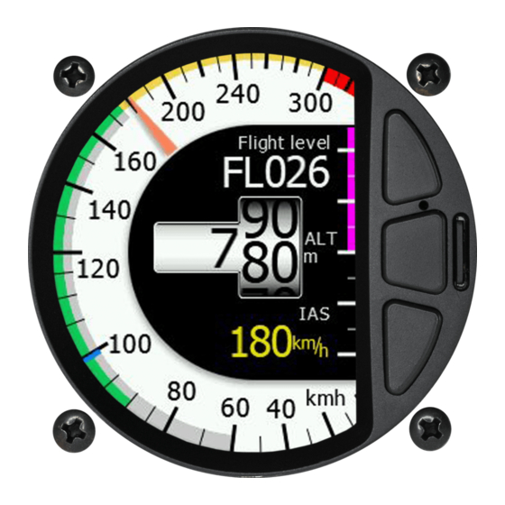
ADI basics 3.1 The ADI at a glance The Airdata indicator or ADI is standalone unit designed to measure and indicate airspeed, altitude and outside air temperature. The unit has standard dimensions that will fit into the instrument panel with an opening of 57 mm diameter. -
Page 6: System Description
November 2020 System description 4.1 Push buttons Airdata indicator has three push buttons. It detects short or long presses of the push button. A short press means just a click; a long press means pushing the button for more than one second. -
Page 7: Navigating Menus
Rev #02 Version 1.0 November 2020 4.4.1 Navigating menus When you press middle button for longer time, you will get into setup menu. Press upper and lower button to move focus. Quickly press middle button to enter submenu. Long press middle button to exit submenu or select Exit option in menu. -
Page 8: Spin Control
Rev #02 Version 1.0 November 2020 4.4.4 Spin control Spin control is used to select a numerical value. Press middle button to enter edit mode. Currently selected value will be highlighted in blue. Use upper and lower button to increase or decrease value. -
Page 9: Operating Modes
November 2020 Operating modes The Airdata indicator has only one main screen, quick menu for QNH and setup mode. When powered on, main screen will be shown. Short press any button to access QNH menu. Long press middle button to enter setup mode 5.1 Main screen... -
Page 10: Setup Mode
Rev #02 Version 1.0 November 2020 While flying QNH display will looks like next picture. QNH display will be automatically closed few seconds after last button was pressed. 5.3 Setup mode Long press middle button to enter setup mode. Setup is used to configure your Airdata indicator. -
Page 11: Display
Rev #02 Version 1.0 November 2020 5.3.1 Display Use this menu to set brightness, customize numerical parameters, set theme color and needle size. Display row 1 and Display row 2 are used to select values which are shown in top row or bottom row. -
Page 12: Airspeed
Rev #02 Version 1.0 November 2020 5.3.2 Airspeed In this menu user can define speed markings, airspeed calibration table and method for true airspeed calculation. 5.3.2.1 Speeds ADI allows user to define all the speed markings for the dial. Please refer to aircraft manual to enter appropriate speeds. -
Page 13: Tas Method
OAT probe. 5.3.5 Battery Airdata indicator can also shows battery information in case it is running on batteries. Select battery type from the list or enter values manually. Page 13 of 18... -
Page 14: Warnings
Rev #02 Version 1.0 November 2020 5.3.6 Warnings The indicator can display warnings for user defined altitudes and speeds. Warning will be displayed in center of the screen with red blinking background and critical parameter written in the middle of the screen. 5.3.6.1 Altitude warning Two altitude warnings can be defined. -
Page 15: Units
Rev #02 Version 1.0 November 2020 5.3.7 Units In this menu you can define system of measure for all the data. Select from predefined sets or change each unit separately. 5.3.8 System Time In this menu the user can set the local time and date. Available is also an offset from UTC. UTC is used within the recorder. -
Page 16: Wiring And Static Ports
No connection Ground RS232 RX (data in) RS232 TX (data out) Ground 6.2 Pressure ports connections Two ports are on the back of Airdata indicator P static pressure port and P pitot or static total total pressure port. Page 16 of 18... -
Page 17: Installation
Version 1.0 November 2020 Installation The Airdata indicator requires a standard 57mm cut-out. Power supply scheme is compatible to any FLARM device with RJ12 connector. On the back it is fitted with two pressure ports for total pressure and static pressure. -
Page 18: Revision History
Rev #02 Version 1.0 November 2020 Revision history Date Comments September 2020 Initial release November 2020 Updated Ch. 4.2 Page 18 of 18...
Need help?
Do you have a question about the Airdata indicator and is the answer not in the manual?
Questions and answers