Advertisement
Quick Links
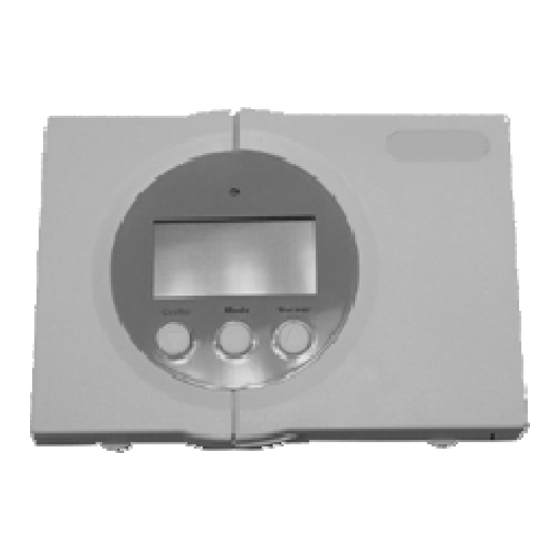
INSTALLATION MANUAL
Programmable
Temperature & Humidity
HEAT
COOL &
2 HEAT - 2 COOL
Meets Residential California Title 24
MULTI-STAGE
Complete Control
Digital Thermostat
International Comfort Products
1 For All
:
78
8 00
74
o
Am
M
o
COOL
AUTO
70
HEAT
o
Cooler
Mode
Warmer
HEAT
PUMP
PROGRAMMABLE
616 01 1012 00
P/N TSTAT0713
2005
Advertisement

Subscribe to Our Youtube Channel
Summary of Contents for HEIL 1 For All TSTAT0713
- Page 1 INSTALLATION MANUAL P/N TSTAT0713 1 For All Programmable Temperature & Humidity 8 00 COOL AUTO HEAT Cooler Mode Warmer HEAT HEAT COOL & PUMP 2 HEAT - 2 COOL Meets Residential California Title 24 MULTI-STAGE PROGRAMMABLE Complete Control Digital Thermostat International Comfort Products 2005 616 01 1012 00...
-
Page 2: Table Of Contents
Table Of Contents PREPARATION REMOVE OLD THERMOSTAT INSTALL BACKPLATE & WIRE WIRING DIAGRAMS CALIBRATION TEST OPERATION TROUBLESHOOTING CAUTION Follow Installation Instructions carefully. DISCONNECT POWER TO THE HEATER AND AIR CONDITIONER BEFORE REMOVING THE OLD THERMOSTAT AND WARNING INSTALLING THE NEW THERMOSTAT. International Comfort Products 2005 P/N TSTAT0713... -
Page 3: Preparation
STEP #1 PREPARATION 8 00 Proper installation of the TSTAT0713 will be COOL AUTO HEAT accomplished by following these step by step instructions. If you are unsure about any of these steps, call a qualified technician for assistance. Assemble tools as shown below. 8 00 COOL AUTO... -
Page 4: Remove Old Thermostat
STEP #2 REMOVE OLD THERMOSTAT 8 00 Turn off the power to the Heating/Air COOL AUTO HEAT Conditioning system at the main fuse panel. Most residential systems have a separate breaker for disconnecting power to the furnace. Remove the cover of the old thermostat. 8 00 COOL AUTO... -
Page 5: Install Backplate & Wire
STEP #3 INSTALL BACKPLATE & WIRE Remove the backplate connector from the rear 8 00 COOL AUTO HEAT of the TSTAT0713 and attach it to the wall. Install wires as directed below. When finished, snap TSTAT0713 on to backplate. 8 00 If the terminal designations on your old COOL AUTO... -
Page 6: Wiring Diagrams
Sample Wiring Diagrams 5 Wire, 1 Stage Cooling, 1 Stage Heat Residential Gas or Electric Heat*, Electric Cool, split systems & package units W1/O/B DEHUM RS+5 RSGND 5 conductor, 18 gauge unshielded cable from the thermostat to the equipment. 24 vac common 24 vac return Fan relay Compressor relay... - Page 7 Sample Wiring Diagrams 6 Wire, 2 Stage Cooling, 1 Stage Heat Residential 2 Stage Cooling with Gas or Electric Heat* W1/O/B DEHUM RS+5 RSGND 6 conductor, 18 gauge unshielded cable from the thermostat to the equipment. 24 vac common 24 vac return Fan relay Compressor relay 1st stage heat circuit...
- Page 8 Sample Wiring Diagrams 6 Wire, 1 Stage Cooling, 2 Stage Heat Residential & Commercial 1 Stage Cooling with 2 Stage Gas or Electric Heat* W1/O/B DEHUM RS+5 RSGND 6 conductor, 18 gauge unshielded cable from the thermostat to the equipment. 24 vac common 24 vac return Fan relay...
- Page 9 Sample Wiring Diagrams 7 Wire, 2 Stage Cooling, 2 Stage Heat Commercial Gas or Electric Heat *, Electric Cool, split systems & package units, including Commercial Heat Pumps ** If using a Residential heat pump, this option must be set to ON during Advanced Setup.
- Page 10 Sample Wiring Diagrams 5 Wire, 1 Stage Cooling, 1 Stage Heat - Heat Pump Residential Heat Pumps*, split systems & package units. No auxiliary heat. W1/O/B DEHUM RS+5 RSGND 5 conductor, 18 gauge unshielded cable from the thermostat to the equipment. 24 vac common 24 vac return Fan relay...
- Page 11 Sample Wiring Diagrams 6 Wire, 2 Stage Cooling, 1 Stage Heat - Heat Pump* Residential Heat Pumps*, split systems & package units. No auxiliary heat. W1/O/B DEHUM RS+5 RSGND 6 conductor, 18 gauge unshielded cable from the thermostat to the equipment. 24 vac common 24 vac return Fan relay...
- Page 12 Sample Wiring Diagrams 6 Wire, 1 Stage Cooling, 2 Stage Heat - Heat Pump* Most residential split and package heat pumps with auxiliary heat W1/O/B DEHUM RS+5 RSGND 6 conductor, 18 gauge unshielded cable from the thermostat to the equipment. 24 vac common 24 vac return Fan relay...
- Page 13 Sample Wiring Diagrams 7 Wire, 2 Stage Cooling, 2 Stage Heat - Heat Pump* Most residential split and package Heat Pumps with auxiliary Heat. If using a Commercial heat pump, this option should be set to OFF during Advanced Setup. W1/O/B DEHUM RS+5...
- Page 14 Sample Wiring Diagrams Accessory Wiring - All Units Installation of outdoor temperature sensor, and humidification system. W1/O/B DEHUM RS+5 RSGND 3 conductor, 18 gauge unshielded cable from the thermostat to the remote sensor. RS-GND Optional wiring for humidity system HUMIDIFIER RS+V Optional outdoor sensor Pages 5, 8, 22, and 24 of Owner’s Manual...
-
Page 15: Calibration
Calibration Every TSTAT0713 is calibrated before it leaves the factory. 8 00 COOL AUTO HEAT Under normal circumstances there will never be a need to recalibrate the TSTAT0713 again. To accommodate special needs, the thermostat may be recalibrated following these steps: 1. -
Page 16: Test Operation
STEP #4 TEST OPERATION Turn the power on to the Heating/Air 8 00 COOL AUTO HEAT Conditioning system. Press the MODE button repeatedly until 8 00 COOL AUTO the COOL icon appears on the display. HEAT Press the UP or DOWN buttons until the set temperature is 10 degrees below room temperature. -
Page 17: Troubleshooting
TROUBLESHOOTING SYMPTOM: The HVAC equipment does not 8 00 COOL AUTO HEAT attempt to turn on. CAUSE: The 5-minute compressor lockout may prevent the air conditioner from turning on, for a period of time. REMEDY: Consult the Owner's Manual in the Setup section to defeat the cycles per hour and compressor timeguard.
Need help?
Do you have a question about the 1 For All TSTAT0713 and is the answer not in the manual?
Questions and answers