
Related Manuals for Anritsu MA24104A


Summary of Contents for Anritsu MA24104A
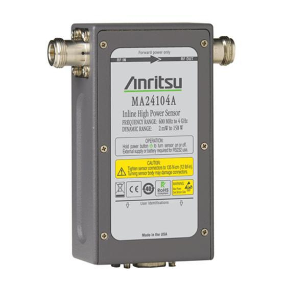
- Page 1 User Guide MA24104A Inline High Power Sensor Average Power, 600 MHz to 4 GHz Anritsu Company PN: 10585-00016 490 Jarvis Drive Revision: A Morgan Hill, CA 95037-2809 Printed: February 2009 Copyright 2009 Anritsu Company...
- Page 2 .NET are all registered trademarks of the Microsoft Corporation. NOTICE Anritsu Company has prepared this manual for use by Anritsu Company personnel and customers as a guide for the proper installation, operation and maintenance of Anritsu Company equipment and computer programs. The drawings, specifications, and information contained herein are the property of Anritsu Company, and any unauthorized use or disclosure of these drawings, specifications, and information is prohibited;...
- Page 3 (i.e. hard disk, CD-ROM, or other storage device), or installed/ loaded into any appropriate Anritsu product. All rights not expressly granted are reserved to ACUS. This Grant of License is not subject to transfer or assignment by Licensee.
-
Page 5: Table Of Contents
Optimizing the Readings ..........3-13 MA24104A UG... - Page 6 Using the Demo Application ........... B-1 Appendix C—Upgrading the Firmware Index PN: 10585-00016, Rev. A MA24104A UG...
-
Page 7: Chapter 1-General Information
All Anritsu power sensors are assigned a unique seven digit serial number, such as “0701012”. The serial number is printed on a label that is affixed to the unit. When ordering parts or corresponding with Anritsu Customer Service, please use the correct serial number with reference to the specific instrument's model number (for example, model MA24104A power sensor, serial number: 0701012). -
Page 8: Customer Asset Tag Placement
Preparation for Storage/Shipment General Information Customer Asset Tag Placement When affixing an asset tag to the MA24104A, please use the area indicated below to insure that the asset tag is retained with the product during service. Customer Asset Tag Figure 1-1. -
Page 9: Chapter 2-Installation (Pc Only)
• PC or laptop with a USB port and CD-ROM drive 2-3 Driver Installation The driver must be installed before the MA24104A power sensor can be used. Follow the steps below as a guide for proper installation: 1. Insert the installation CD in the drive of your computer. If the installation menu does not start automatically, open the file named Startup.htm located on the CD. - Page 10 3. Click Next in the following screen to begin the installation process. Figure 2-2. Anritsu Power Meter Installation 4. Browse for the installation folder, select the desired permissions, and then click Next. The default installation directory is: C:\Program Files\Anritsu\AnritsuPowerMeter Figure 2-3. Anritsu Power Meter Installation PN: 10585-00016, Rev. A...
- Page 11 Installation (PC Only) Driver Installation 5. Select I Agree to the license agreement, and then click Next. Figure 2-4. License Agreement 6. Select Next to continue with the software installation. Figure 2-5. Confirm Installation MA24104A UG PN: 10585-00016, Rev. A...
- Page 12 Application Installation Complete 8. Connect the MA24104A power sensor to the USB port of the PC with the supplied USB cable, then press and hold the ON button for one second. The status LED lights green indicating that the sensor is turned PN: 10585-00016, Rev.
- Page 13 Next. If the Wizard does not start, refer to Appendix C, “Serial Port Compatibility” for troubleshooting information. Figure 2-8. Found New Hardware Wizard 10. Select Install from a list or specific location (Advanced), and then click Next. Figure 2-9. Found New Hardware Wizard MA24104A UG PN: 10585-00016, Rev. A...
- Page 14 11. Select Don’t search. I will choose the driver to install, and then click Next. Figure 2-10. Found New Hardware Wizard 12. Select the hardware type Computer, and then click Next. Figure 2-11. Found New Hardware Wizard PN: 10585-00016, Rev. A MA24104A UG...
- Page 15 14. Browse to the location on your hard drive where you installed the program. If the default settings were chosen during the application installation, click Browse..., as shown below, and then select: C:\Program Files\Anritsu\AnritsuInlinePowerMeter\AnritsuMA24104A.inf 15. Click Open, then click OK. Figure 2-13. Install From Disk MA24104A UG PN: 10585-00016, Rev. A...
- Page 16 Driver Installation Installation (PC Only) 16. Select Anritsu MA24104A from the list, and then click Next as shown below. Figure 2-14. Found New Hardware Wizard 17. The Hardware Installation Warning dialog will appear as shown in Figure 2-15. Click Continue Anyway.
- Page 17 Figure 2-16. Found New Hardware Wizard 19. The MA24104A is now ready for use. Launch the Anritsu Power Meter application from the new desktop icon or from the Start | Programs menu. Refer to Chapter 3 for information about using the Anritsu Power Meter application.
-
Page 19: Chapter 3-Using The Power Sensor
Chapter 3 — Using the Power Sensor 3-1 Introduction This chapter provides information on using the Anritsu Power Meter application with the MA24104A inline high power sensor. It provides a description of the Graphical User Interface, various settings of the application, basic procedures for Making Measurements, as well as information about Uncertainty of a Measurement. -
Page 20: Graphical User Interface
Data Entry Fields Status Bar Figure 3-2. Anritsu Power Meter Application Overview The Anritsu Power Meter application always launches in the default state as described below: • Frequency: 600 MHz • Power Units: W • Averages: 1 • Fixed Offset: 0 dB •... -
Page 21: Buttons
• Averages Button: Sets the number of averages from 1 to 256 (see Table 3-1 for guidelines) • Fixed Offset Button: Sets the offset from –100 dB to +100 dB Figure 3-3. Example of an Active Entry Field MA24104A UG PN: 10585-00016, Rev. A... -
Page 22: Display Window
Display Window (Normal mode with Offset Table On) Status Bar The status bar displays the model number, serial number, cal factor frequency, averaging number, and operational status of the sensor (see Figure 3-6). Figure 3-6. Status Bar PN: 10585-00016, Rev. A MA24104A UG... -
Page 23: Menu Bar
• Upgrade Firmware: Launches the firmware upgrade sequence. Refer to Appendix C for a procedure on upgrading the firmware. • Connected to COM Port Number: Displays the COM port number that is currently assigned to the power sensor. Figure 3-8. Tools Menu MA24104A UG PN: 10585-00016, Rev. A... -
Page 24: Data Logging Menu
One- or two-digit month dd: One- or two-digit day hhmmss: Two digit hours (24-hour clock), minutes, and seconds The filename and location can be selected or changed as desired. Figure 3-10. DataLogging Save Dialog PN: 10585-00016, Rev. A MA24104A UG... -
Page 25: Power Graph
The graph is continuously updated in real time. Figure 3-12. Power Graph Menu Note: Unavailable selections become available after the Power Graph is started. MA24104A UG PN: 10585-00016, Rev. A... - Page 26 • Power, Y-axis: 60 dBm (1000 Watts) Clicking Setup opens the Graph Setup dialog (below) where the scales of time and power axes can be changed. Power is in dBm and time is in minutes. Figure 3-14. PowerGraph Setup Dialog PN: 10585-00016, Rev. A MA24104A UG...
-
Page 27: Offset Table
Also, a check mark is applied in front of the Offset Table On selection in the OffsetTable menu. 4. To clear all of the entries in the table, click the Clear Table button. MA24104A UG PN: 10585-00016, Rev. A... - Page 28 Figure 3-16. Save As Dialog 6. To recall a response, click Open in the Offset Entry screen, select the file, and then click Apply. Similarly, S2P files can be imported as shown below: Figure 3-17. Open Dialog 3-10 PN: 10585-00016, Rev. A MA24104A UG...
-
Page 29: Session Restore
Figure 3-18. Offset Table Menu (Offset Table Off Status) Session Restore The Anritsu Power Meter application retains the set up information of a session, even if the inline high power sensor becomes disconnected from the PC. When the inline high power sensor is reconnected, the changed properties (if different from default) will be highlighted for five seconds as a reminder of the changed set up. -
Page 30: Basic Power Measurement
Using the Power Sensor Basic Power Measurement 1. Connect the sensor to a computer or Anritsu Master™ series instrument as shown in Figure 3-20 and turn the power sensor ON by pressing the sensor’s power button for 1 second. Note: Operation with the RS232 port requires an external power supply or batteries installed in the sensor. A USB connection does not require an external power supply or batteries. -
Page 31: Connecting The Sensor
RF power from the connection to a level 20 dB below the noise floor of the power sensor. For the MA24104A power sensor, this level is less than –20 dBm. It is preferable to leave the sensor connected to the DUT test port so that ground noise and thermal EMF (electro-magnetic fields) are zeroed out of the measurement. - Page 32 Table 3-1, describes the number of averages needed to attain a certain noise level for a particular power level measurement with the Low Aperture Time mode setting. Table 3-1. MA24104A Averaging Table (Low Aperture Time, Default Mode) Number of Number of...
-
Page 33: Measurement Considerations
If averages are not calculated over many of these beats, or an integer number of beats, errors can result. This is not unique to the MA24104A and can be an issue with any power sensor/meter and any sampled data system. -
Page 34: Settling Time
Settling Time The MA24104A samples power continuously every 70 ms in the Low Aperture Time (LAT) mode and 700 ms in the High Aperture Time (HAT) mode. The sensor’s front end and digitizer settles completely to a step change in power in this amount of time. -
Page 35: Uncertainty Of A Measurement
Two measurement uncertainty calculations for Low Aperture Time mode are shown for the MA24104A in Table 3-3. The MA24104A is used to measure the power of a 1 GHz, +50.0 dBm and +10 dBm CW signal from a signal source with a 1.5:1 VSWR and a load having a 1.2:1 VSWR. The example is based on 128 measurement averages. - Page 36 Zero Drift 20 mW/100 W = 0.0% Noise Calculations at +10 dBm (10 mW): Noise 100 μW/10 mW = 1.0% Zero Set 398 μW/10 mW = 4.0% Zero Drift 119 μW/10 mW = 1.2% 3-18 PN: 10585-00016, Rev. A MA24104A UG...
-
Page 37: Error States
This section details some of the error messages that may appear on the application screen. In most cases, the error condition can be easily corrected. The status LED will light amber when an error state occurs. If not, note the error message and contact an Anritsu Service Center. Table 3-5. -
Page 39: Chapter 4-Remote Operation
4-1 Introduction Once connected to a PC using a USB cable, the MA24104A shows up as an RS-232 Serial COM port on the PC. You can check the COM port number from the Tools drop-down menu or by using the Windows control panel. -
Page 40: Remote Operation Command Details
Remarks: This command should be sent before exiting the user application. IDN? Description: Gets identification information from the sensor. Syntax: IDN? + LF Return Value: ANRITSU, Model #, Serial #, Module Serial #, firmware version PWR? Description: Gets the power reading from the power sensor. Syntax: PWR? + LF... - Page 41 Status.b1 -> Not Used Status.b2 -> ADC_CH2_OR (Temperature over range) Status.b3 -> ADC_CH3_OR (Detector A over ranged) Status.b4 -> ZERO_ERROR_DET_A Status.b5 -> ZERO_ERROR_DET_B Status.b6 -> TEMP_ERROR (Temperature beyond operating range) Status.b7 -> Not Used MA24104A UG PN: 10585-00016, Rev. A...
- Page 42 Remarks: This command applies when RS232 connectivity is used with battery power. In this mode, the sensor will not go into sleep mode if the RS-232 serial port cable is disconnected from the host. PN: 10585-00016, Rev. A MA24104A UG...
-
Page 43: Appendix A-Connector Care And Handling
Also, such compliance will ensure that Power Sensor failures are not due to misuse or abuse – two failure modes not covered under the Anritsu warranty. Beware of destructive pin depth mating connectors Destructive pin depth of mating connectors is the major cause of failure in the field. - Page 44 Mechanical shock will significantly reduce their service life. Avoid applying excessive power The MA24104A sensor is rated at 150 W maximum continuous input power given a load VSWR of 3:1 or less. Exceeding the maximum input power level may permanently damage the internal components, rendering the power sensor useless.
-
Page 45: Appendix B-Sample Visual Basic Code
B-2 Using the Demo Application Once connected to the PC using the USB cable, the MA24104A shows up as a Serial port device on the PC. You can check the COM port number using the device manager in the Windows® control panel. - Page 46 Using the Demo Application ************************************************************************ // This sample program shows how to control Anritsu MA24104A inline high power sensor using //Microsoft Visual basic 6.0 Option Explicit Public gstrInputBuffer As String 'Event handler for InitializeComPort button Private Sub btnInitializeComPort_Click() Call SetCommPort(Val(Trim(txtCOMPORTNo.Text)))
- Page 47 If MSComm1.PortOpen = True Then 'Stop sensor from making measurements txtCommand.Text = "STOP" Call btnSend_Click 'Wait for half a second after sending START command Delay (0.5) MSComm1.PortOpen = False End If 'Close the app End Sub MA24104A UG PN: 10585-00016, Rev. A...
- Page 48 Public Sub Delay(ByVal Seconds As Single) Dim fStartTimer As Single Dim fFinish As Single fStartTimer = Timer DoEvents fFinish = Timer If Abs(fFinish - fStartTimer) > Seconds Then Exit Do End If Loop End Sub ************************************************************************ PN: 10585-00016, Rev. A MA24104A UG...
-
Page 49: Appendix C-Upgrading The Firmware
Figure C-1. Firmware Upgrade Dialog Note: If this is the first time that you are upgrading the sensor’s firmware, you will need to install the MA24104A upgrade driver. Follow the driver installation procedure as outlined in Section 2-3, starting with step 9, and select the MA24104A Upgrade Mode driver when prompted from: C:\Program Files\Anritsu\AnritsuPowerMeter\UpgradeModeDriver\AnritsuMA24104AUpgradeMode.inf... - Page 50 4. Once the upgrade driver has been installed, click OK on the dialog below. Figure C-3. Firmware Upgrade Dialog 5. Select the power sensor that you intend to upgrade from the drop-down list box. Figure C-4. Firmware Upgrade Application PN: 10585-00016, Rev. A MA24104A UG...
- Page 51 6. Click Load Hex File and select the HEX file from the directory in which it was saved. Figure C-5. Open File Dialog Warning: Do Not disconnect the MA24104A power sensor from the USB port or interrupt the firmware write sequence as this will cause an unrecoverable programming error.
- Page 52 On (note that the LED will illuminate). Click OK to complete the firmware upgrade procedure. Figure C-7. Firmware Upgrade Dialog 9. Launch the Anritsu Power Meter application to begin using the upgraded sensor. PN: 10585-00016, Rev. A MA24104A UG...
-
Page 53: Index
......3-7 contents, shipping ......1-1 MA24104A UG PN: 10585-00016, Rev. A... - Page 54 ........1-2 Index-2 PN: 10585-00016, Rev. A MA24104A UG...
- Page 55 ......3-17 zero set ......3-17 MA24104A UG PN: 10585-00016, Rev. A...
Need help?
Do you have a question about the MA24104A and is the answer not in the manual?
Questions and answers