Makita PM7650H Technical Information
Petrol mist blower
Hide thumbs
Also See for PM7650H:
- Instruction manual (112 pages) ,
- Owner's and safety manual (84 pages) ,
- Instruction manual (112 pages)
Table of Contents
Advertisement
Quick Links
T
ECHNICAL INFORMATION
Models No.
Description
C
ONCEPT AND MAIN APPLICATIONS
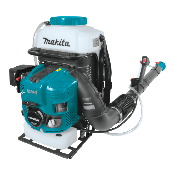
Model PM7650H is a Petrol mist blower equipped with
75.6cm³ 4-stroke engine in compliance with all major
exhaust emission regulations in the world, and features
16m max. horizontal spraying range and ergonomically
designed chemical tank.
This product is also available with E25 compatibility
for Brazil only as Model PM7650HG.
S
pecification
Type
Displacement: cm³ (cu.in)
Fuel
Engine
Max. output power: kW (PS)
Max. engine speed: min.
Idling speed: min.
Compliance with exhaust emission regulations
CARB Tier 3, EPA Phase 2, EU Stage 2
Engine oil
Carburetor
Starting system
Fuel tank capacity: L (US oz)
Chemical tank capacity: L (US oz)
Max. spray range (horizontal):
Max. air velocity: m/s
Max. air volume*
:
3
Dry weight*
: kg (lbs)
4
Brazil: E25 gasoline
*1
This product is not in compliance with the regulations of San Dimas.
*2
with nozzle
*3
with Straight pipe 330
*4
S
tandard equipment
Oil bottle (containing 220ml of oil) ......... 1
Hand strap ............................................... 1
Box wrench ............................................. 1
Screwdriver ............................................. 1
Diffusion cover
(Wide spray attachment) ......................... 1
Hose clamp 76 ......................................... 3
Hose clamp 100 ....................................... 1
Note: The standard equipment for the tool shown above may vary by country.
O
ptional accessories
Straight pipe 330
Straight pipe 630
Bent top pipe 630 (20º)
PM7650H
Petrol Mist Blower
¹ = rpm
ˉ
¹ = rpm
ˉ
m (ft)
m³/h
O ring set
Air cleaner element
4-stroke
75.6 (4.61)
Straight gasoline*
2.7 (3.67) [at 7,000 min.
7,400
2,800
;
*2
SAE10W-30 oil
in Class SF or higher of API Classification
Diaphragm
Recoil starter, with mechanical decompression
1.8 (61)
15.0 (507)
16.0 (52)
13.3 (29.3)
Flexible pipe ............................................ 1
Straight pipe 330 ..................................... 1
Straight pipe 630 (for Brazil only)
Bent top pipe 630 (20º) (for Brazil only)
Tube 10-500 (for Brazil only)
H
W
Dimensions: mm (")
Length (L)
Width (W)
Height (H)
1
¹]
ˉ
Yes
85
845
PRODUCT
P 1/26
L
420 (16-1/2)
440 (17-1/4)
595 (23-1/2)
Nozzle 0.7
Nozzle 0.8
Advertisement
Table of Contents

Related Manuals for Makita PM7650H


Summary of Contents for Makita PM7650H
- Page 1 Description Petrol Mist Blower ONCEPT AND MAIN APPLICATIONS Model PM7650H is a Petrol mist blower equipped with 75.6cm³ 4-stroke engine in compliance with all major exhaust emission regulations in the world, and features 16m max. horizontal spraying range and ergonomically designed chemical tank.
-
Page 2: Necessary Repairing Tools
(2) replace Gasket with new one. [3] LUBRICANT/ADHESIVE APPLICATION • Apply Makita grease N No.2 to Spiral spring in Recoil starter. • When disassembling the engine, apply ThreeBond 1216 to the mating surface between Crankcase and Cylinder block. (Fig. 75) [4] DISASSEMBLY/ASSEMBLY [4]-1. - Page 3 P 3/26 epair [4] DISASSEMBLY/ASSEMBLY [4]-2. Nozzle section DISASSEMBLING (1) Remove Tube 10-500 from Nozzle adapter complete by removing Hose clamp 14. (Fig. 1) (2) By unscrewing M5x18 Pan head screw, Nozzle adapter complete can be separated from Top adapter and Straight pipe. (Fig. 1) (3) Remove Diffusion cover from Top adapter by turning it counterclockwise.
- Page 4 P 4/26 epair [4] DISASSEMBLY/ASSEMBLY [4]-3. Cock section DISASSEMBLING (1) Remove Tube 10-500 and Tube 10-750 from Cock body by removing two 14 Hose clamps. (Fig. 6) (2) Remove Body holder complete from Control lever assembly by unscrewing two 4x14 Tapping screws. (Fig. 7) Fig.
- Page 5 P 5/26 epair [4] DISASSEMBLY/ASSEMBLY [4]-4. Pipe section DISASSEMBLING (1) Remove Straight pipe from Swivel pipe complete. (Fig. 10) (2) Remove Swivel pipe complete from Flexible pipe by removing Hose clamp76. (Fig. 11) (3) Remove Control lever assembly from Swivel pipe complete by unscrewing M5x25 Pan head screw. (Fig. 11) Fig.
- Page 6 P 6/26 epair [4] DISASSEMBLY/ASSEMBLY [4]-5. Recoil complete, Engine cover, Fuel tank DISASSEMBLING Fig. 13 (1) Remove Recoil complete by unscrewing three M5x20 Pan head screws. (Fig. 13) (2) Remove Engine cover by unscrewing Recoil complete four 5x20 Tapping screws. (Fig. 14) M5x20 Pan head screw (3 pcs)
- Page 7 P 7/26 epair [4] DISASSEMBLY/ASSEMBLY [4]-5. Recoil complete, Engine cover, Fuel tank (cont.) DISASSEMBLING (3) Remove the fuel tubes of Tube assembly from Carburetor and Primer pump. (Fig. 15) (4) Remove Fuel tank from Frame complete by unscrewing three M6x12 Pan head screws. (Fig. 16) Fig.
-
Page 8: Control Cable
P 8/26 epair [4] DISASSEMBLY/ASSEMBLY [4]-6. Control cable Fig. 19 DISASSEMBLING Wire band raised portion of Elbow (1) Using cutting pliers, cut and remove Wire band that holds Elbow Cable tube to Elbow. (Fig. 19) (2) Remove Control cable and switch cords from the hook ON/OFF of Volute case 2, then disconnect the bullet terminal of ON/OFF... - Page 9 P 9/26 epair [4] DISASSEMBLY/ASSEMBLY [4]-7. Tank complete (Chemical tank) DISASSEMBLING (1) Remove Tube 10-750 from Joint strainer by removing Hose clamp 14. (Fig. 24) (2) Remove Tube 10-300 from Pressure pipe by removing Hose clamp 14. (Fig. 25) (3) Remove Band R and Band L from Tank complete by removing four E-4 Stop rings with small pliers then by sliding four size 5 Pins.
- Page 10 P 10/26 epair [4] DISASSEMBLY/ASSEMBLY [4]-7. Tank complete (Chemical tank) (cont.) DISASSEMBLING (4) Remove Cushion by unscrewing five M5x12 Pan head screws. (Fig. 27) (5) Unscrew two M6x30 Pan head screws to disconnect Tank complete from Tank holder. Be careful not to lose Flat washer 6 and Compression spring 20. (Fig. 28) (6) Remove Tank complete from Frame complete by unscrewing four M6x30 Pan head screws.
-
Page 11: Blower Section
P 11/26 epair [4] DISASSEMBLY/ASSEMBLY [4]-8. Blower section DISASSEMBLING (1) Remove Frame complete from Lower frame holder by unscrewing two M6x20 Pan head screws. (left of Fig. 32) (2) Remove Lower frame holder and Compression spring 17 from Frame holder on each side of Volute case 2. (right of Fig. - Page 12 P 12/26 epair [4] DISASSEMBLY/ASSEMBLY [4]-8. Blower section (cont.) DISASSEMBLING (7) Remove O ring 93 from Elbow. (Fig. 35) Fig. 35 Fig. 36 (8) Remove Pressure pipe from Volute case 1 4x18 Tapping screw by unscrewing 4x18 Tapping screw. (Fig. 36) Note: Be careful not to lose Flat washer 4.
-
Page 13: Frame Section
P 13/26 epair [4] DISASSEMBLY/ASSEMBLY [4]-9. Frame section DISASSEMBLING Fig. 39 Remove Guard from Frame complete by unscrewing six M4x25 Pan head screws. (Fig. 39) Frame complete ASSEMBLING Assemble by reversing the disassembly procedure. Guard M4x25 Pan head screw (6 pcs) -
Page 14: Ignition System
P 14/26 epair [4] DISASSEMBLY/ASSEMBLY [4]-10. Ignition system CHECKING PLUG CAP (1) Remove Plug cap from Spark plug, then check the continuity between Plug cap spring and the ground (earth) terminal of Ignition coil with a circuit tester. (Fig. 40) (2) If there is no or intermittent continuity, check the continuity between Ignition cable and Plug cap spring by following the procedure described below. - Page 15 P 15/26 epair [4] DISASSEMBLY/ASSEMBLY [4]-10. Ignition system (cont.) CHECKING SPARK PLUG WARNING !! • When a spark is produced, high-voltage current is delivered from Ignition coil to Spark plug. It is, therefore, very dangerous to pull Recoil starter knob with your hand on Ignition cable. Be sure to keep your hands off from Ignition cable when checking for spark.
- Page 16 P 16/26 epair [4] DISASSEMBLY/ASSEMBLY [4]-10. Ignition system (cont.) MOUNTING IGNITION COIL (1) Insert 0.3mm leaf of Feeler gauge set (1R366) between Ignition coil and the magnet of Flywheel complete. Ignition coil will be attracted to the magnet through the Feeler gauge. Then, without removing the Feeler gauge, fasten Ignition coil to the engine with two M4x20 Socket head bolts.
-
Page 17: Starter Unit
Spiral spring Spiral spring counterclockwise towards the center of Reel. (Fig. 50) (2) Apply a little amount of Makita grease N No.2 to the whole surface of Spiral spring. (3) Put a new Starter rope through Starter case complete. (Fig. 51) Then tie one end to Starter knob and the other to Reel by making a knot as shown in Fig. - Page 18 P 18/26 epair [4] DISASSEMBLY/ASSEMBLY [4]-11. Starter unit (cont.) ASSEMBLING RECOIL STARTER (5) While turning Reel counterclockwise, mount it in Starter case complete. Then hook the inner end of Spiral spring in the slit of the shaft portion of Starter case complete. (Fig. 53) Note: You need not use force to mount Reel in place.
- Page 19 P 19/26 epair [4] DISASSEMBLY/ASSEMBLY [4]-12. Carburetor section REMOVING CARBURETOR Fig. 56 Fig. 57 (1) Remove Air cleaner cover complete from Air cleaner plate by unscrewing M5x25 Pan head screw. (Fig. 56) (2) Remove Air cleaner element. (Fig. 58) (3) Remove two M5x70 Pan head screws that fasten Air cleaner plate and Carburetor to Cylinder head complete.
-
Page 20: Assembling Carburetor
P 20/26 epair [4] DISASSEMBLY/ASSEMBLY [4]-12. Carburetor section (cont.) ASSEMBLING CARBURETOR Fig. 61 Assemble by reversing the disassembly procedure. Note: Make sure that the assembling direction of each part is correct. VACUUM LEAK TEST OF CARBURETOR Carburetor Connect 1R127 with the fuel inlet of Carburetor, 1R127 then increase the testing pressure up to 0.05Mpa. - Page 21 P 21/26 epair [4] DISASSEMBLY/ASSEMBLY [4]-13. Stop switch section CHECKING STOP SWITCH Check the continuity between the bullet terminals Fig. 66 on the two lead wires extending from Control lever with a circuit tester. (Fig. 66) Control lever If Stop switch functions properly, there will be no continuity with the switch ON and there will be continuity with the switch OFF.
- Page 22 P 22/26 epair [4] DISASSEMBLY/ASSEMBLY [4]-15. Engine block DISASSEMBLING ENGINE BLOCK (1) It is highly recommended to drain the oil system of Engine block before starting disassembling because the oil remaining there will drip out to delay your operation. (2) From the engine section, remove the following parts (Fig. 69): Ignition coil, Flywheel complete, Rocker cover complete, Rocker arm assembly (2 pcs), Push rod (2 pcs), Cam lifter (2 pcs), Camgear assembly, Insulator complete, Air cleaner, Carburetor, Spark plug, Exhaust muffler (3) Remove the assembly of Cylinder head and Cylinder block.
- Page 23 (1) Connect Piston with Crankshaft complete by inserting Piston pin into place; there is no front/back to Piston. Note: Be sure to apply a little amount of Makita grease N No.2 to Needle roller bearing. (2) Secure Piston pin by mounting Ring spring 12 onto each end of Piston pin.
- Page 24 P 24/26 epair [4] DISASSEMBLY/ASSEMBLY [4]-15. Engine block (cont.) ASSEMBLING ENGINE BLOCK (7) Adjust the valve clearance by following the procedure described below: 1. Align the two positioning mark of Flywheel with the edge of Crankcase as shown in Fig. 76. 2.
- Page 25 P 25/26 epair [4] DISASSEMBLY/ASSEMBLY [4]-16. Tightening torque specifications Application Tightening torque (for fastening A to B) Fastener (N.m) Crankcase Cylinder block M6x30 Hex socket head bolt 10.0 - 12.0 Retainer plate Crankcase M4x10 Hex socket head bolt 2.0 - 3.5 Drain bolt (M8x12 Bolt) Oil case M8x12 Bolt...
- Page 26 P 26/26 epair [4] DISASSEMBLY/ASSEMBLY [4]-16. Tightening torque specifications Application Tightening torque (for fastening A to B) Fastener (N.m) Cushion Tank complete M5x12 Pan head screw 1.8 - 3.5 Fuel tank Frame complete M6x12 Pan head screw 2.0 - 3.5 Engine cover complete Volute case 2 5x20 Tapping screw...
Need help?
Do you have a question about the PM7650H and is the answer not in the manual?
Questions and answers