Advertisement
QUICK START GUIDE
HARRIER 3G-SDI
CAMERA INTERFACE BOARD
Introduction
This guide is designed to get you quickly up and running with the Harrier 3G-SDI Evaluation Kit
(AS-CIB-3GSDI-002-EVAL-B) and the Harrier 3G-SDI Camera Interface Board
(AS-CIB-3GSDI-002-A). The interface board can be purchased as a pre-assembled camera module
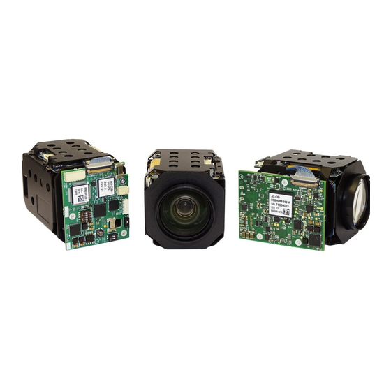
with Active Silicon's Harrier 10x AF-Zoom Camera (AS-CIB-3GSDI-002-10LHD-A) or Harrier 36x AF-
Zoom Camera (AS-CIB-3GSDI-002-36LGHD-A, shown in Figure 1).
This document should be read in conjunction with the Harrier 3G-SDI Camera Interface Board
datasheet and other documents available on
Interface Board - Downloads section):
https://www.activesilicon.com/products/harrier-3g-sdi-camera-interface-board-75-ohm/
a.
Figure 1: Harrier 3G-SDI Camera Interface Board
mounted on
a. Harrier 10x AF-Zoom Camera and
b. Harrier 36x AF-Zoom Camera Global Shutter
The Harrier 3G-SDI Camera Interface Board can be customized to deliver application specific
functions; USB/HDMI, HDMI-only or USB-only interface boards are also available.
For more details contact Active Silicon.
September 2020
HARRIER 3G-SDI CAMERA INTERFACE BOARD
Active Silicon's website,
b.
QUICK START GUIDE
Version 1.2.AS - September 2020
(see Harrier 3G-SDI Camera
Figure 2: Block diagram of Harrier 3G-
SDI Camera Interface Board showing
position of connectors and SW1, SW2
and SW3 DIP switches
Page 1 of 8
Advertisement
Table of Contents

Subscribe to Our Youtube Channel
Related Manuals for Active Silicon HARRIER 3G-SDI CAMERA INTERFACE BOARD


Summary of Contents for Active Silicon HARRIER 3G-SDI CAMERA INTERFACE BOARD
- Page 1 Active Silicon’s Harrier 10x AF-Zoom Camera (AS-CIB-3GSDI-002-10LHD-A) or Harrier 36x AF- Zoom Camera (AS-CIB-3GSDI-002-36LGHD-A, shown in Figure 1). This document should be read in conjunction with the Harrier 3G-SDI Camera Interface Board datasheet and other documents available on Active Silicon’s website,...
- Page 2 QUICK START GUIDE HARRIER 3G-SDI CAMERA INTERFACE BOARD Version 1.2.AS - September 2020 Evaluation Kit Contents The Evaluation Kit (AS-CIB-3GSDI-002-EVAL-B) contains all the parts needed to evaluate the Harrier 3G-SDI Camera Interface Board. Note that the evaluation kit does not include a Harrier 3G-SDI Camera Interface Board or camera, these need to be ordered separately.
- Page 3 (SW302). When the Power Switch (and camera power supply) is switched ON the PWR ON LED will illuminate. For more information please see the Harrier Evaluation Board datasheet on the Active Silicon website (see Harrier 3G-SDI Camera Interface Board Evaluation Kit - Downloads section). September 2020 Page 3 of 8...
- Page 4 QUICK START GUIDE HARRIER 3G-SDI CAMERA INTERFACE BOARD Version 1.2.AS - September 2020 Setting up the System To get the 3G-SDI Camera Interface Board running, please follow the instructions below: 1. Connect the camera to the camera interface board connector (J1) using a KEL30 multi-way cable (connector type: KEL USL00-30L).
- Page 5 Transceivers connected to J3 pins 1 and 2 will be shut down. Applications using this configuration should leave J3 pins 1 and 2 unconnected. Table 1: Harrier 3G-SDI Camera Interface Board DIP switch settings for selection of the camera serial communications interface type. September 2020...
- Page 6 On the Harrier Evaluation Board, J103 supports RS-232 and TTL communications, J203 supports RS-485 and TTL communications. The Harrier 3G-SDI Camera Interface Board is shipped by default with all DIP switches in the “OFF” position. In this state, the board is configured for RS-232 communications.
- Page 7 QUICK START GUIDE HARRIER 3G-SDI CAMERA INTERFACE BOARD Version 1.2.AS - September 2020 Notes: 1) “Default camera mode”: on power-up, the camera will start in the video format/mode that was set/being used when it was last powered down. The video mode can then be changed using a VISCA serial command).
- Page 8 The BNC connector on the Harrier Evaluation Board will supply the analog video output of the camera interface board. The Harrier 3G-SDI Camera Interface Board generates the analog signal by downscaling the camera digital output. To enable this, the camera must be set into 720p50/720p60 output mode.
Need help?
Do you have a question about the HARRIER 3G-SDI CAMERA INTERFACE BOARD and is the answer not in the manual?
Questions and answers