Sign In
Upload
Download
Table of Contents
Contents
Add to my manuals
Delete from my manuals
Share
URL of this page:
HTML Link:
Bookmark this page
Add
Manual will be automatically added to "My Manuals"
Print this page
×
Bookmark added
×
Added to my manuals
Manuals
Brands
Motorola Manuals
Antenna
HAD4021A
Installation manual
Motorola HAD4021A Installation Manual
Vhf vehicle roof-top antennas
Hide thumbs
1
2
3
4
5
6
7
8
9
10
11
12
13
14
15
16
page
of
16
Go
/
16
Contents
Table of Contents
Bookmarks
Advertisement
Table of Contents
1
Product Safety and RF Exposure Compliance
2
Document Copyrights
3
Fcc Requirements
4
Recommended Location
5
Required Tools and Materials
6
Installation Procedure
7
Antenna Installation
Download this manual
M
Title Page
Motorola Solutions, Inc.
1303 E. Algonquin Rd.,
Schaumburg, IL 60196-1078, U.S.A.
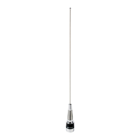
VHF Vehicle Roof-Top Antennas
HAD4021A
HAD4022A
Installation Manual
68007024095-C
Table of
Contents
Previous
Page
Next
Page
1
2
3
4
5
Advertisement
Table of Contents
Need help?
Do you have a question about the HAD4021A and is the answer not in the manual?
Ask a question
Questions and answers
Related Manuals for Motorola HAD4021A
Antenna Motorola HAD4006A Manual
Mobile quarter-wave antennas roof mount and trunk lip mount (8 pages)
Antenna Motorola RAD4020ARB Installation Manual
Mobile 1/4-wave antennas, roof mount (8 pages)
Antenna Motorola HAD4022A Installation Manual
Vhf vehicle roof-top antennas (16 pages)
Antenna Motorola PMAE4030 Installation Manual
Combination gps antenna/mount (94 pages)
Antenna Motorola HAF4015 Installation Manual
Mobile motorcycle antenna (30 pages)
Antenna Motorola Spectrum Series Installation Manual
Base loaded mobile antennas (23 pages)
Antenna Motorola PMAN4009 User Manual
Window mount antenna (21 pages)
Antenna Motorola PMAN4008 User Manual
Gnss (gps/galileo/qzss/glonass) through-hole mount antenna (32 pages)
Antenna Motorola PMAN4002 Installation Manual
Gps magnetic mount antenna (17 pages)
Antenna Motorola Nitro SLX 5000 Installation Manual
(44 pages)
Antenna Motorola RRA-4935 Instructions Manual
Mobile gain antennas 890-960 mhz (6 pages)
Antenna Motorola ASTRO APX 3000 Quick Start Manual
Digital portable radios flexible antenna (2 pages)
Antenna Motorola PMAN4010 Installation Manual
Gnss (gps/galileo/qzss/glonass) magnetic mount antenna (21 pages)
Antenna Motorola PMAN5100 Installation Manual
Covert wifi window mount antenna (10 pages)
Antenna Motorola AN720 Assembly And Installation Instructions Manual
Rfid antennas (23 pages)
This manual is also suitable for:
Had4022a
Table of Contents
Save PDF
Print
Rename the bookmark
Delete bookmark?
Delete from my manuals?
Login
Sign In
OR
Sign in with Facebook
Sign in with Google
Upload manual
Upload from disk
Upload from URL


Need help?
Do you have a question about the HAD4021A and is the answer not in the manual?
Questions and answers