Table of Contents
Advertisement
Quick Links
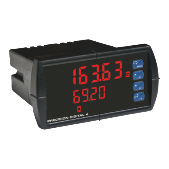
PD6363 Pulse Dual-Input
Rate/Totalizer Instruction Manual
• Pulse, Open Collector, NPN, PNP, TTL, Switch Contact,
Sine Wave (Coil), Square Wave Inputs
• Gate Function for Rate Display of Slow Pulse Rates
• Rate, Total, and Grand Total for Each Input Channel
• Addition, Difference, Average, Multiplication, Division, Min,
Max, Weighted Average, Ratio, Concentration, & More
• NEMA 4X, IP65 Front
• Universal 85-265 VAC, or 12/24 VDC Input Power Models
• Large Dual-Line 6-Digit Display, 0.60" & 0.46"
• Isolated 24 VDC Transmitter Power Supply
• Programmable Display & Function Keys
• 2 or 4 Relays + Isolated 4-20 mA Output Options
• 4-Relay, 2 Analog Output, and I/O External Modules
• USB, RS-232 & RS-485 Serial Communication Options
• Modbus
• Configure, Monitor, and Datalog from a PC with Free
MeterView
PRECISION DIGITAL CORPORATION
233 South Street • Hopkinton MA 01748 USA
Tel (800) 343-1001 • Fax (508) 655-8990
®
RTU Communication Protocol Standard
®
Pro Software
www.predig.com
Advertisement
Table of Contents
Troubleshooting

Related Manuals for Precision Digital Corporation PD6363 Series


Summary of Contents for Precision Digital Corporation PD6363 Series
- Page 1 • Modbus ® RTU Communication Protocol Standard • Configure, Monitor, and Datalog from a PC with Free ® MeterView Pro Software PRECISION DIGITAL CORPORATION 233 South Street • Hopkinton MA 01748 USA Tel (800) 343-1001 • Fax (508) 655-8990 www.predig.com...
- Page 2 Corporation shall not be held liable for damages resulting from such improper use. Limited Warranty Precision Digital Corporation warrants this product against defects in material or workmanship for the specified period under “Specifications” from the date of shipment from the factory. Precision Digital’s liability under this limited warranty shall not exceed the...
-
Page 3: Table Of Contents
Model PD6363 Pulse Dual-Input Rate/Totalizer Instruction Manual Table of Contents INTRODUCTION ------------------------------------------------------------ 6 ORDERING INFORMATION --------------------------------------------- 7 SPECIFICATIONS ---------------------------------------------------------- 8 General ------------------------------------------------------------------------------- 8 Dual Pulse Inputs --------------------------------------------------------------- 10 Dual Rate/Totalizer ------------------------------------------------------------- 12 Relays ------------------------------------------------------------------------------ 13 Isolated 4-20 mA Transmitter Output ------------------------------------ 14 Modbus®... - Page 4 Model PD6363 Pulse Dual-Input Rate/Totalizer Instruction Manual Setting Up the Meter (setup) ------------------------------------------------ 39 Setting the Input Signal (Input) ------------------------------------------ 40 Setting the Totalizer Features (total) ------------------------------ 40 Setting the Dual-Input Mode (nmode) -------------------------------- 40 Setting the Rate, Total, & Grand Total Units/Tags (units) -------- 44 Setting the Decimal Point (dEc pt) -------------------------------------- 45 Programming the Rate/Totalizer (prog) -------------------------------- 46 Input Calibration Method (InCAL) ------------------------------------- 47...
- Page 5 Model PD6363 Pulse Dual-Input Rate/Totalizer Instruction Manual Acknowledging Relays ------------------------------------------------------ 67 Setting Up the Interlock Relay (Force On) Feature ------------------ 68 Scaling the 4-20 mA Analog Output (Aout) ---------------------------- 68 Reset Menu (reset) ------------------------------------------------------------ 69 Control Menu (Contrl) -------------------------------------------------------- 69 Setting Up the Password (pass) ------------------------------------------- 69 Protecting or Locking the Meter Functions ----------------------------- 70 Total Reset Password &...
-
Page 6: Introduction
Model PD6363 Pulse Dual-Input Rate/Totalizer Instruction Manual Table of Figures Figure 1. 1/8 DIN Panel Cutout Dimensions ........17 Figure 2. Panel Mounting Details ............17 Figure 3. Meter Dimensions - Side View ........... 18 Figure 4. Meter Dimensions - Top View ..........18 Figure 5. -
Page 7: Ordering Information
Model PD6363 Pulse Dual-Input Rate/Totalizer Instruction Manual ORDERING INFORMATION Standard Models 85-265 VAC 12/24 VDC Options Installed Model Model PD6363-6R0 PD6363-7R0 No options PD6363-6R2 PD6363-7R2 2 relays (PD1102*) PD6363-6R3 PD6363-7R3 4-20 mA output (PD1103*) PD6363-6R4 PD6363-7R4 4 relays (PD1104*) PD6363-6R5 PD6363-7R5 2 relays &... -
Page 8: Specifications
Model PD6363 Pulse Dual-Input Rate/Totalizer Instruction Manual SPECIFICATIONS Except where noted all specifications apply to operation at +25°C. General DISPLAY Upper display: 0.60" (15 mm) high, red LEDs Lower display: 0.46" (12 mm) high, red LEDs 6 digits each (-99999 to 999999), with lead zero blanking DISPLAY Eight user selectable intensity levels INTENSITY... - Page 9 Model PD6363 Pulse Dual-Input Rate/Totalizer Instruction Manual POWER 85-265 VAC 50/60 Hz, 90-265 VDC, 20 W max OPTIONS or jumper selectable 12/24 VDC ± 10%, 15 W max FUSE Required external fuse: UL Recognized, 5 A max, slow blow; up to 6 meters may share one 5 A fuse ISOLATED Terminals P+ &...
-
Page 10: Dual Pulse Inputs
Model PD6363 Pulse Dual-Input Rate/Totalizer Instruction Manual Dual Pulse Inputs TWO INPUTS Field selectable: Pulse or square wave 0-5 V, 0-12 V, or 0-24 V @ 30 kHz; TTL; open collector 4.7 kΩ pull-up to 5 V @ 30 kHz; NPN or PNP transistor, switch contact 4.7 kΩ pull-up to 5 V @ 40 Hz;... - Page 11 Model PD6363 Pulse Dual-Input Rate/Totalizer Instruction Manual LOW VOLTAGE Sensitivity: 40 mVp-p to 8Vp-p MAG PICKUP MINIMUM INPUT 0.001 Hz FREQUENCY Minimum frequency is dependent on high gate setting. MAXIMUM INPUT 30,000 Hz (10,000 for low voltage mag pickup) FREQUENCY INPUT Pulse input: Greater than 300 kΩ...
-
Page 12: Dual Rate/Totalizer
Model PD6363 Pulse Dual-Input Rate/Totalizer Instruction Manual Dual Rate/Totalizer RATE DISPLAY -99999 to 999999, lead zero blanking. INDICATION TOTAL DISPLAY 0 to 999,999; automatic lead zero blanking. & TOTAL Up to 999,999,999 with total-overflow feature. “ ” is OVERFLOW displayed to the left of total overflow and ▲ LED is illuminated. -
Page 13: Relays
Model PD6363 Pulse Dual-Input Rate/Totalizer Instruction Manual PROGRAMMABLE 0.1 and 999.9 seconds; applied to the first relay assigned DELAY to total or grand total. ON RELEASE If the meter is programmed to reset total to zero automatically when the preset is reached, then a delay will occur before the total is reset. -
Page 14: Isolated 4-20 Ma Transmitter Output
Model PD6363 Pulse Dual-Input Rate/Totalizer Instruction Manual Isolated 4-20 mA Transmitter Output OUTPUT Input channels A or B, rate, total, or grand total; channel C; SOURCE max or min for channel A or B; highest or lowest max or min of A and B; set points 1-8; Modbus input; or manual control mode SCALING RANGE 1.000 to 23.000 mA for any display range CALIBRATION... -
Page 15: Compliance Information
Model PD6363 Pulse Dual-Input Rate/Totalizer Instruction Manual COMPLIANCE INFORMATION Safety UL & c-UL LISTED USA & Canada UL 508 Industrial Control Equipment UL FILE NUMBER E160849 FRONT PANEL UL Type 4X, NEMA 4X, IP65; panel gasket provided LOW VOLTAGE EN 61010-1:2010 DIRECTIVE Safety requirements for measurement, control, and laboratory use... -
Page 16: Safety Information
Model PD6363 Pulse Dual-Input Rate/Totalizer Instruction Manual Note: Testing was conducted on PD6300 Series meters installed through the covers of grounded metal enclosures with cable shields grounded at the point of entry representing installations designed to optimize EMC performance. Declaration of Conformity available at www.predig.com SAFETY INFORMATION CAUTION: Read complete WARNING: Risk of... - Page 17 Model PD6363 Pulse Dual-Input Rate/Totalizer Instruction Manual • Panel thickness: 0.04" - 0.25" (1.0 mm - 6.4 mm). Recommended minimum panel thickness to maintain Type 4X rating: 0.06" (1.5 mm) steel panel, 0.16" (4.1 mm) plastic panel. • Remove the two mounting brackets provided with the meter (back-off the two screws so that there is ¼"...
-
Page 18: Mounting Dimensions
Model PD6363 Pulse Dual-Input Rate/Totalizer Instruction Manual MOUNTING DIMENSIONS Figure 3. Meter Dimensions - Side View Figure 4. Meter Dimensions - Top View... -
Page 19: Configuration For 12 Or 24 Vdc Power Option
Model PD6363 Pulse Dual-Input Rate/Totalizer Instruction Manual Configuration for 12 or 24 VDC Power Option Do not exceed voltage rating of the selected configuration. Warning! Meters equipped with the 12/24 VDC power option are shipped from the factory ready to operate from 24 VDC. To configure the meter for 12 VDC power: Remove all the connectors. -
Page 20: Transmitter Supply Voltage Selection (P+, P-)
Model PD6363 Pulse Dual-Input Rate/Totalizer Instruction Manual Transmitter Supply Voltage Selection (P+, P-) All meters, including models equipped with the 12/24 VDC power option, are shipped from the factory configured to provide 24 VDC power for the transmitter or sensor. If the transmitter requires 5 or 10 VDC excitation, the internal jumper J4 must be configured accordingly. -
Page 21: Connectors Labeling
Model PD6363 Pulse Dual-Input Rate/Totalizer Instruction Manual Connectors Labeling The connectors’ label, affixed to the meter, shows the location of all connectors available with requested configuration. Do not connect any equipment other than Precision Digital’s expansion modules, cables, or meters to the RJ45 M-LINK connector. - Page 22 Model PD6363 Pulse Dual-Input Rate/Totalizer Instruction Manual Pulse Input Connections The following figures show examples of signal connections. Figure 9: Flowmeters Powered by Internal Power Supply Figure 10: Flowmeters Powered by External Supply Figure 11: Self-Powered Magnetic Pickup Coil Flowmeters...
-
Page 23: Configure Input Type And Level Switches
Model PD6363 Pulse Dual-Input Rate/Totalizer Instruction Manual Figure 12: NPN open Collector Input Figure 13: PNP Sensor Powered by Internal Supply Figure 14: Switch Input Connections Configure Input Type and Level Switches Channel A and B each have an internal input type configuration switch. These switches must be set to the correct input type and level. -
Page 24: Modbus Rtu Serial Communications
Model PD6363 Pulse Dual-Input Rate/Totalizer Instruction Manual switch can be set for mV, PNP, or NPN. For details on what input type to select, see Pulse Input Connections starting on page 22. To configure the meter for 12 VDC power: Remove all the connectors. -
Page 25: Switching Inductive Loads
Model PD6363 Pulse Dual-Input Rate/Totalizer Instruction Manual Switching Inductive Loads The use of suppressors (snubbers) is strongly recommended when switching inductive loads to prevent disrupting the microprocessor’s operation. The suppressors also prolong the life of the relay contacts. Suppression can be obtained with resistor-capacitor (RC) networks assembled by the user or purchased as complete assemblies. -
Page 26: F4 Digital Input Connections
Model PD6363 Pulse Dual-Input Rate/Totalizer Instruction Manual F4 Digital Input Connections A digital input, F4, is standard on the meter. This digital input connected with a normally open closure across F4 and COM, or with an active low signal applied to F4. Figure 18. -
Page 27: External Relay, Analog Output, & Digital I/O Connections
Model PD6363 Pulse Dual-Input Rate/Totalizer Instruction Manual External Relay, Analog Output, & Digital I/O Connections The relay, analog out, and digital I/O expansion modules PDA1004, PDA1011, and PDA1044 are connected to the meter using a CAT5 cable provided with each module. The two RJ45 connectors on the expansion modules are identical and interchangeable;... -
Page 28: Setup And Programming
Model PD6363 Pulse Dual-Input Rate/Totalizer Instruction Manual SETUP AND PROGRAMMING The meter has been factory calibrated to read input frequency in Hz (pulses/sec). The calibration equipment is certified to NIST standards. Use the K-Factor menu to match the rate/totalizer with a flowmeter’s k- factor (pulse/unit of measure). -
Page 29: Front Panel Buttons And Status Led Indicators
Model PD6363 Pulse Dual-Input Rate/Totalizer Instruction Manual Front Panel Buttons and Status LED Indicators Button Description Status Symbol Menu Alarm 1-8 indicator Flashing: Relay in Right arrow/F1 manual control mode Up arrow/F2 Channel displayed Flashing: Relay Enter/F3 interlock switch open Notes: Note: F4 is a digital input. -
Page 30: Display Functions & Messages
Model PD6363 Pulse Dual-Input Rate/Totalizer Instruction Manual Display Functions & Messages The following table shows the main menu functions and messages in the order they appear in the menu. Display Parameter Action/Setting Description Setup Enter Setup menu setup Input Enter Input selection menu Input Input Set input operation for channel A (*or B) - Page 31 Model PD6363 Pulse Dual-Input Rate/Totalizer Instruction Manual Display Parameter Action/Setting Description Set rate decimal point (*channel A and B Rate Rate* only) Total Set total decimal point (*channel A and B Total* only) Grand total Set grand total decimal point (*channel A Gtotal* and B only) Program...
- Page 32 Model PD6363 Pulse Dual-Input Rate/Totalizer Instruction Manual Display Parameter Action/Setting Description Program grand total conversion factor Gt CF Grand total conversion factor treset Total reset Program total reset mode: auto or manual Channel A Set total reset modes for channel A (*or B) Ch-A* T rst Total reset...
- Page 33 Model PD6363 Pulse Dual-Input Rate/Totalizer Instruction Manual Display Parameter Action/Setting Description Alternate display of channel B rate and Drgt-b Display rate and grand total B grand total Display Set 1* Displays relay 1(*through 8) set point. Dset 1* Display high A Display high value of channel A D Hi-A Display low A...
- Page 34 Model PD6363 Pulse Dual-Input Rate/Totalizer Instruction Manual Display Parameter Action/Setting Description Set display intensity level from 1 to 8 d-Inty Display intensity RELaY Relay Enter the Relay menu Assignment Assign relays to channels or Modbus Assign Assign 1 Relay 1 (*through 8) assignment Asign1* Assign relay to channel A (*or B or C) Channel A*...
- Page 35 Model PD6363 Pulse Dual-Input Rate/Totalizer Instruction Manual Display Parameter Action/Setting Description Enter relay 1 (*through 8) time delay setup Delay 1 DLY 1* On 1 Set relay 1 On time delay On 1 Off 1 Set relay 1 Off time delay OFF 1 Analog output Enter the Analog output scaling menu...
- Page 36 Model PD6363 Pulse Dual-Input Rate/Totalizer Instruction Manual Display Parameter Action/Setting Description Program password to lock meter unloc Unlocked Locd Locked Enter password to unlock meter Pass 2 Password 2 Set or enter Password 2 Password 3 Set or enter Password 3 Pass 3 Total reset Set or enter a total reset password...
-
Page 37: Main Menu
Model PD6363 Pulse Dual-Input Rate/Totalizer Instruction Manual Main Menu The main menu consists of the most commonly used functions: Reset, Control, Setup , and Password . • Press Menu button to enter Programming Mode then press the Up arrow button to scroll main menu. •... -
Page 38: Setting Numeric Values
Model PD6363 Pulse Dual-Input Rate/Totalizer Instruction Manual Setting Numeric Values The numeric values are set using the Right and Up arrow buttons. Press Right arrow to select next digit and Up arrow to increment digit value. The digit being changed is displayed brighter than the rest. Press and hold up arrow to auto-increment the display value. -
Page 39: Setting Up The Meter (Setup)
Model PD6363 Pulse Dual-Input Rate/Totalizer Instruction Manual Setting Up the Meter (setup) The Setup menu is used to select: Total enable/disable and channel A and B input modes Units for A & B rate, total & grand total, and C Decimal positions for A &... -
Page 40: Setting The Input Signal (Input)
Model PD6363 Pulse Dual-Input Rate/Totalizer Instruction Manual Setting the Input Signal (Input) There are two internal slide switches, located inside the rear meter housing to the left of the input connector, which must be configured according to the input levels and types. See Configure Input Type and Level Switches on page 23 for details. - Page 41 Model PD6363 Pulse Dual-Input Rate/Totalizer Instruction Manual Ch-A Totalizer Add/Subtract by Ch-B Input (ud AB) Total of channel A will add or subtract as determined by the state of input channel B. Channel A total will add at each falling edge if input B is high, and subtract at each rising edge if input B is low.
- Page 42 Model PD6363 Pulse Dual-Input Rate/Totalizer Instruction Manual Ch-B Totalizer Add/Subtract by Digital Input (ud BI) Total of channel B will add or subtract as determined by the state of a digital input. Channel B total will add at each falling edge if an assigned digital input is high, and subtract at each rising edge if an assigned digital input is low.
- Page 43 Model PD6363 Pulse Dual-Input Rate/Totalizer Instruction Manual subtract as determined by the state of input channel B. Channel A total will add at each rising edge if channel B is high, and at each falling edge if channel B is low. Channel A total will subtract at each rising edge if channel B is low, and at each falling edge if channel B is high.
-
Page 44: Setting The Rate, Total, & Grand Total Units/Tags (Units)
Model PD6363 Pulse Dual-Input Rate/Totalizer Instruction Manual Setting the Rate, Total, & Grand Total Units/Tags (units) Enter the channel A and B rate, total, grand total, and math channel C units (or custom tags) that will be displayed if alternating units is selected in the units menu, or d unit is selected as the lower display parameter. -
Page 45: Setting The Decimal Point (Dec Pt)
Model PD6363 Pulse Dual-Input Rate/Totalizer Instruction Manual Setting the Decimal Point (dEc pt) The decimal point for any channel, rate, total, or grand total, may be set with up to five decimal places or with no decimal point at all. Pressing the Right arrow moves the decimal point one place to the right until no decimal point is displayed, and then it moves to the leftmost position. -
Page 46: Programming The Rate/Totalizer (Prog)
Model PD6363 Pulse Dual-Input Rate/Totalizer Instruction Manual Programming the Rate/Totalizer (prog) It is very important that one reads the following information before programming the meter: • The meter has been factory calibrated to read input frequency in Hz (pulses/sec). The calibration equipment is certified to NIST standards. -
Page 47: Input Calibration Method (Incal)
Model PD6363 Pulse Dual-Input Rate/Totalizer Instruction Manual ® MeterView Pro Software The meter can also be programmed using the PC-based MeterView Pro software available for free download at www.predig.com. Data logging for one meter at a time is available with MeterView Pro software. -
Page 48: Scaling The Meter Without A Signal Source (Scal-A, Scal-B)
Model PD6363 Pulse Dual-Input Rate/Totalizer Instruction Manual Scaling the Meter without a Signal Source (SCAL-A, SCAL-B) The inputs can be scaled to display the process variables in engineering units. A signal source is not needed to scale the meter; simply program the inputs and corresponding display values. -
Page 49: Calibrating The Meter With External Source (Cal-A,Cal-B)
Model PD6363 Pulse Dual-Input Rate/Totalizer Instruction Manual Minimum Input Span The minimum allowed input span is 1.0 Hz, which is the minimum difference between input 1 and input 2 signals required to complete the calibration or scaling of the meter. Calibrating the Meter with External Source (CAL-A,CAL-B) To scale the meter without a signal source refer to Scaling the Meter without a Signal Source ( SCAL-A , SCAL-B ), page 48 . -
Page 50: Totalizer Setup (Tsetup)
Model PD6363 Pulse Dual-Input Rate/Totalizer Instruction Manual Totalizer Setup (tsetup) The time base and total and grand total conversion factors for input channels A and B are located in the Totalizer Setup menu. The time base is determined by the rate programming. Enter the time unit of the programmed rate scale. -
Page 51: Setting The Display Parameters & Intensity (Dsplay)
Model PD6363 Pulse Dual-Input Rate/Totalizer Instruction Manual Setting the Display Parameters & Intensity (dsplay) The upper display ( Big ) can be programmed to display: Ch-A rate ( D Ch-A ) Ch-B rate ( D Ch-B ) Ch-C math channel ( D Ch-C ) Toggle Ch-A &... -
Page 52: Display Setup Menu
Model PD6363 Pulse Dual-Input Rate/Totalizer Instruction Manual Display Intensity: The meter has eight display intensity levels to give the best performance under various lighting conditions. Select intensity 8 for outdoor applications. The default intensity setting is 8. Display Setup Menu See Setting the Display Parameters &... -
Page 53: Setting The Relay Operation (Relay)
Model PD6363 Pulse Dual-Input Rate/Totalizer Instruction Manual Setting the Relay Operation (relay) This menu is used to set up the assignment and operation of the relays. During setup, the relays do not follow the input and they will remain in the state found prior to entering the Relay menu. -
Page 54: Setting The Relay Assignment (Assign)
Model PD6363 Pulse Dual-Input Rate/Totalizer Instruction Manual Setting the Relay Assignment (asSign) -
Page 55: Setting The Relay Action (Act)
Model PD6363 Pulse Dual-Input Rate/Totalizer Instruction Manual Setting the Relay Action (Act) Operation of the relays is programmed in the Action menu. The relays may be set up for any of the following modes of operation: Automatic reset (non-latching) Automatic + manual reset at any time (non-latching) Latching (manual reset only, at any time) Latching with Clear (manual reset only after alarm condition has cleared) -
Page 56: Programming Set And Reset Points
Model PD6363 Pulse Dual-Input Rate/Totalizer Instruction Manual Programming Set and Reset Points High alarm indication: program set point above reset point. Low alarm indication: program set point below reset point. The deadband is determined by the difference between set and reset points. -
Page 57: Relay And Alarm Operation Diagrams
Model PD6363 Pulse Dual-Input Rate/Totalizer Instruction Manual Relay and Alarm Operation Diagrams The following graphs illustrate the operation of the relays, status LEDs, and ACK button. High Alarm Operation (Set > Reset) For Manual reset mode, ACK can be pressed anytime to turn "off" relay. To detect a new alarm condition, the signal must go below the set point, and then go above it. -
Page 58: Low Alarm Operation (Set < Reset)
Model PD6363 Pulse Dual-Input Rate/Totalizer Instruction Manual Low Alarm Operation (Set < Reset) For Manual reset mode, ACK can be pressed anytime to turn "off" relay. For relay to turn back "on", signal must go above set point, and then go below it. -
Page 59: High Alarm With Fail-Safe Operation (Set > Reset)
Model PD6363 Pulse Dual-Input Rate/Totalizer Instruction Manual High Alarm with Fail-Safe Operation (Set > Reset) Note: Relay coil is energized in non-alarm condition. In case of power failure, relay will go to alarm state. -
Page 60: Low Alarm With Fail-Safe Operation (Set < Reset)
Model PD6363 Pulse Dual-Input Rate/Totalizer Instruction Manual Low Alarm with Fail-Safe Operation (Set < Reset) Note: Relay coil is energized in non-alarm condition. In case of power failure, relay will go to alarm state. -
Page 61: Pump Alternation Control Operation
Model PD6363 Pulse Dual-Input Rate/Totalizer Instruction Manual... -
Page 62: Rate Relay Sampling Operation
Model PD6363 Pulse Dual-Input Rate/Totalizer Instruction Manual Rate Relay Sampling Operation Input Reset Sample Sample Sample Time Time Time Relay When the signal crosses the set point, the relay trips and the sample time starts. After the sample time has elapsed, the relay resets. The cycle repeats every time the set point is crossed, going up for high alarms and going down for low alarms. -
Page 63: Time Delay Operation
Model PD6363 Pulse Dual-Input Rate/Totalizer Instruction Manual Time Delay Operation The following graphs show the operation of the time delay function. When the signal crosses the set point, the On time delay timer starts and the relay trips when the time delay has elapsed. If the signal drops below the set point (high alarm) before the time delay has elapsed, the On time delay timer resets and the relay does not change state. -
Page 64: Relay Operation Details
Model PD6363 Pulse Dual-Input Rate/Totalizer Instruction Manual Relay Operation Details Overview The relay capabilities of the meter expand its usefulness beyond simple indication to provide users with alarm and control functions. These capabilities include front panel alarm status LEDs as well as either 2 or 4 optional internal relays and/or 4 external relays expansion module. -
Page 65: Front Panel Leds
Model PD6363 Pulse Dual-Input Rate/Totalizer Instruction Manual Front Panel LEDs The LEDs on the front panel provide status indication for the following: Status Status Alarm 1 Alarm 5 Alarm 2 Alarm 6 Alarm 3 Alarm 7 Alarm 4 Alarm 8 The meter is supplied with four alarm points that include front panel LEDs to indicate alarm conditions. -
Page 66: Non-Latching Relay (Auto)
Model PD6363 Pulse Dual-Input Rate/Totalizer Instruction Manual Non-Latching Relay (Auto) Automatic reset only Condition Relay Normal Alarm Ack (No effect) Normal In this application, the meter is set up for automatic reset (non-latching relay). Acknowledging the alarm while it is still present has no effect on either the LED or the relay. -
Page 67: Latching Relay (Lt-Clr)
Model PD6363 Pulse Dual-Input Rate/Totalizer Instruction Manual Latching Relay (Lt-Clr) Manual reset only after alarm condition has cleared Condition Relay Normal Alarm Ack (No effect) Normal In this application, the meter is set up for manual reset only after the signal passes the reset point (alarm condition has cleared). -
Page 68: Setting Up The Interlock Relay (Force On) Feature
Model PD6363 Pulse Dual-Input Rate/Totalizer Instruction Manual Setting Up the Interlock Relay (Force On) Feature Relays 1-4 can be set up as interlock relays. To set up the relays for the interlock feature: 1. Access the Setup – Relay – Action menu and set the action to off. 2. -
Page 69: Reset Menu (Reset)
Model PD6363 Pulse Dual-Input Rate/Totalizer Instruction Manual Reset Menu (reset) The Reset menu is used to reset the maximum (peak) value of Ch-A and Ch-B rate ( rst Hi ), minimum (valley) reading of Ch-A and Ch-B rate ( rst Lo ), both high and low value of Ch-A and Ch-B rate ( rst HL ), Ch-A total ( tot A ) or Ch-B total ( tot B ), Ch-A grand total ( Gtot A ) or Ch-B grand total ( Gtot B ), both Ch-A and Ch-B totals ( tot AB ), or both Ch-A and Ch-B grand totals ( Gt AB ). -
Page 70: Protecting Or Locking The Meter Functions
Model PD6363 Pulse Dual-Input Rate/Totalizer Instruction Manual Record the password for future reference. If appropriate, it may be recorded in the space provided. Model: Serial Number: Password 1: __ __ __ __ __ __ Password 2: __ __ __ __ __ __ Password 3: __ __ __ __ __ __ Total... -
Page 71: Making Changes To A Password Protected Meter
Model PD6363 Pulse Dual-Input Rate/Totalizer Instruction Manual Making Changes to a Password Protected Meter If the meter is password protected, the meter will display the message Locd (Locked) when the Menu button is pressed. Press the Enter button while the message is being displayed and enter the correct password to gain access the menu. -
Page 72: Advanced Features Menu
Model PD6363 Pulse Dual-Input Rate/Totalizer Instruction Manual Advanced Features Menu To simplify the setup process, functions not needed for most applications are located in the Advanced Features menu. Press and hold the Menu button for three seconds to access the advanced features of the meter. -
Page 73: Advanced Features Menu & Display Messages
Model PD6363 Pulse Dual-Input Rate/Totalizer Instruction Manual Advanced Features Menu & Display Messages The following table shows the functions and messages of the Advanced Features menu in the order they appear in the menu. Display Parameter Action/Setting Gate Enter Gate function menu Gate Low gate Program Low gate value... - Page 74 Model PD6363 Pulse Dual-Input Rate/Totalizer Instruction Manual Display Parameter Action/Setting C = (A-B+P)*F Difference difabs Abs difference C = ((Absolute value of (A-B))+P)*F Average C = (((A+B)/2)+P)*F Multiplication C = ((A*B)+P)*F nmulti Divide C = ((A/B)+P)*F Divide Max of A or B C = ((High value of channel A or B)+P)*F Hi-ab Min of A or B...
- Page 75 Model PD6363 Pulse Dual-Input Rate/Totalizer Instruction Manual Display Parameter Action/Setting Set direction of grand total count Gtot C G. total count Count up Count up Douwn Count down Count down Count start Enter count down start value C strt Analog output Program analog output parameters AoutPr programming...
-
Page 76: Gate Function (Gate)
Model PD6363 Pulse Dual-Input Rate/Totalizer Instruction Manual Gate Function (Gate) The gate function ( Gate ) is the first option in the Advanced Features menu. There are two settings for the Gate , low gate ( Lo G ) and high gate ( Hi G ). -
Page 77: Contact De-Bounce Filter (Filter)
Model PD6363 Pulse Dual-Input Rate/Totalizer Instruction Manual Contact De-Bounce Filter (FiLter) The filter function ( Filter ) is the second option in the Advanced Features menu. The filter function ( FiLter ) can be used for applications where the meter is set up to count pulses generated by switch contacts. The filter value can be set anywhere between 2 and 50, the higher the value, the greater the filtering. -
Page 78: Modbus Rtu Serial Communications (Serial)
Model PD6363 Pulse Dual-Input Rate/Totalizer Instruction Manual Modbus RTU Serial Communications (serial) The meter is equipped with serial communications capability as a standard feature using Modbus RTU Serial Communication Protocol. To communicate with a computer or other data terminal equipment, an RS-232, RS-485, or USB adapter option is required;... -
Page 79: Select Menu (Select)
Model PD6363 Pulse Dual-Input Rate/Totalizer Instruction Manual Select Menu (SElect) The Select menu is used to select the signal input conditioning function applied to the inputs, math function for A & B, constants, low-flow cutoff, total count direction (up or down from a preset amount), and analog output programming. -
Page 80: Signal Input Conditioning (Functn)
Model PD6363 Pulse Dual-Input Rate/Totalizer Instruction Manual Signal Input Conditioning (Functn) The Function menu is used to condition the linear input signal. Multi- point linearization is part of the linear function selection. Each input channel signal input conditioning function is programmed independently. Multi-Point Linearization (Linear) Meters are set up at the factory for linear function with 2-point linearization. -
Page 81: Math Function (Nmath)
Model PD6363 Pulse Dual-Input Rate/Totalizer Instruction Manual Math Function (nmath) The Math menu is used to select the math function that will determine the channel C value. These math functions are a combination of input channels A and B, and will display when channel C is selected in the Display menu. -
Page 82: Math Constants (Const)
Model PD6363 Pulse Dual-Input Rate/Totalizer Instruction Manual Math Constants (Const) The Math Constants menu is used to set the constants used in channel C math. The math functions include adder constant P, and factor constant F. The Adder constant (P) may be set from -99.999 to 999.999. The Factor constant (F) may be set from 0.001 to 999.999. -
Page 83: Totalizer Count Up/Down (Count)
Model PD6363 Pulse Dual-Input Rate/Totalizer Instruction Manual Totalizer Count Up/Down (Count) The totalizer count up/down menu may be used to program the total and grand total to either count up from 0 when reset or count down from a programmed value when reset. Total and grand total may have their countdown numbers programmed individually from 0 to 999999. - Page 84 Model PD6363 Pulse Dual-Input Rate/Totalizer Instruction Manual Analog Output Source The analog output source can be based on either of the input channel rate, total, or grand totals (Ch-A, Ch-B), the math channel (Ch-C), maximum stored value of either input channel (Hi-A, Hi-B), minimum stored value of either input channel (Lo-A, Lo-B), maximum or minimum of A and B (Hi-AB, Lo-AB), relay set points, or the Modbus input.
-
Page 85: Programmable Function Keys User Menu (User)
Model PD6363 Pulse Dual-Input Rate/Totalizer Instruction Manual Programmable Function Keys User Menu (user) The User menu allows the user to assign the front panel function keys F1, F2, F3, F4 (digital input) and up to eight digital inputs to access most of the menus or to activate functions immediately (e.g. -
Page 86: Meter Copy Function (Copy)
Model PD6363 Pulse Dual-Input Rate/Totalizer Instruction Manual Display Description Display Description Reset channel B Display grand total D gtot Rst gb grand total Max on big display Reset max Big Hi Rst Hi (Channel A) Min on big display Reset min Big Lo Rst Lo (Channel A) - Page 87 Model PD6363 Pulse Dual-Input Rate/Totalizer Instruction Manual Meter Copy or Cloning Instructions Do not connect the two meters to the same signal source while cloning. Internal calibration may be affected. Caution! PDA1200 Meter Copy Cable Figure 27: Meter Copy Connection Connect two meters using a PDA1200 meter copy cable.
-
Page 88: Meter Operation
Model PD6363 Pulse Dual-Input Rate/Totalizer Instruction Manual METER OPERATION The meter accepts two input channels (A and B) of either pulses (e.g. ±40 mV to ± 8V), square wave (0-5 V, 0-12 V, or 0-24 V), open collector NPN, PNP, TTL, or switch contact signals and displays these signals in engineering units from -99999 to 999999. -
Page 89: Front Panel Buttons Operation
Model PD6363 Pulse Dual-Input Rate/Totalizer Instruction Manual Front Panel Buttons Operation Button Description Symbol Press to enter or exit Programming Mode, view settings, or exit max/min readings Press to reset max/min readings or other parameter/function assigned through the User menu Press to display max/min readings for channel A or other parameter/function assigned through the User menu... -
Page 90: Troubleshooting
Model PD6363 Pulse Dual-Input Rate/Totalizer Instruction Manual TROUBLESHOOTING The rugged design and the user-friendly interface of the meter should make it unusual for the installer or operator to refer to this section of the manual. However, due to the many features and functions of the meter, it’s possible that the setup of the meter does not agree with what an operator expects to see. -
Page 91: Reset Meter To Factory Defaults
Model PD6363 Pulse Dual-Input Rate/Totalizer Instruction Manual Reset Meter to Factory Defaults When the parameters have been changed in a way that is difficult to determine what’s happening, it might be better to start the setup process from the factory defaults. Instructions to load factory defaults: Enter the Advanced Features menu. -
Page 92: Factory Defaults & User Settings
Model PD6363 Pulse Dual-Input Rate/Totalizer Instruction Manual Factory Defaults & User Settings The following table shows the factory setting for most of the programmable parameters on the meter. Next to the factory setting, the user may record the new setting for the particular application. Model: ______________ S/N: _______________ Date: ___________ Parameter Display... - Page 93 Model PD6363 Pulse Dual-Input Rate/Totalizer Instruction Manual Parameter Display Default Setting User Setting K-Factor, channel B Fact-B 1.000 Total setup Tsetup Time base, channel A Tbase Total conversion factor, 1.000 T CF Ch-A Grand total conversion 1.000 Gt CF factor, Ch-A Time base, channel B Tbase Total conversion factor,...
- Page 94 Model PD6363 Pulse Dual-Input Rate/Totalizer Instruction Manual Parameter Display Default Setting User Setting Relay 3 set point 300.0 Set 3 Relay 3 reset point 250.0 RSt 3 Relay 4 assignment Channel A rate Ch-A Relay 4 action Automatic Act 4 Relay 4 set point 400.0 Set 4...
- Page 95 Model PD6363 Pulse Dual-Input Rate/Totalizer Instruction Manual Parameter Display Default Setting User Setting Transmit delay 50 ms Tr dly Parity Even Parity Byte-to-byte timeout 010 (0.1 sec) t-byt Math math Math, channel C Adder (constant P) 0.000 Adder Factor (constant F) Factor User user...
-
Page 96: Troubleshooting Tips
Model PD6363 Pulse Dual-Input Rate/Totalizer Instruction Manual Troubleshooting Tips Symptom Check/Action Check power at power connector No display at all Meter is password-protected, enter Not able to change setup or correct six-digit password to unlock programming, Locd is displayed Check: Meter displays error message Signal connections during calibration (Error) -
Page 97: Eu Declaration Of Conformity
EN 55022:2010, EN 61000-6-2:2005, EN 61010-1:2010, and EN 61326:2013 and there were no major technical changes affecting the latest technical knowledge for the products listed above. Product Markings: Signed for and on behalf of Precision Digital Corporation: Name: Jeffrey Peters Company:... - Page 98 Model PD6363 Pulse Dual-Input Rate/Totalizer Instruction Manual How to Contact Precision Digital • For Technical Support please Call: (800) 610-5239 or (508) 655-7300 Fax: (508) 655-8990 Email: support@predig.com • For Sales Support or to place an order please contact your local distributor or Call: (800) 343-1001 or (508) 655-7300 Fax: (508) 655-8990 Email: sales@predig.com...
Need help?
Do you have a question about the PD6363 Series and is the answer not in the manual?
Questions and answers