Table of Contents
Advertisement
Quick Links
Advertisement
Table of Contents

Related Manuals for Gopel Electronic G CAR 6282

Summary of Contents for Gopel Electronic G CAR 6282
- Page 1 G CAR 6282 Manual (Original documentation)
- Page 2 Copyright © 2019 GOEPEL electronics GmbH. All rights reserved. The software described in this manual as well as the manual itself are supplied under license and may be used or copied only in accordance with the terms of the license. The customer may make one copy of the software for safety purposes.
-
Page 3: Table Of Contents
G CAR 6282 Table of Contents 1 Introduction ..........................1 1.1 Notes on this document ...................... 1 1.2 Intended Use ........................1 1.3 EMC Protection Measures ....................2 1.4 EU Declaration of Conformity ....................2 1.5 General Safety Regulations ....................2 1.6 Liability and Warranty Exclusion ................... 2 1.7 Supplied Accessories ......................3 2 Commissioning .......................... - Page 4 G CAR 6282 Index ............................26 G CAR 6282...
- Page 5 2.4 Change of the transceiver ......................7 3.1 Host Side ..........................9 3.2 DUT Side ..........................9 3.3 Transceiver ..........................9 3.4 Block diagram of the G CAR 6282 Multibus Controller ..............11 3.5 Schematic drawing of the socket of the power supply ..............14 G CAR 6282...
- Page 6 G CAR 6282 List of Tables 1.1 Symbols ........................... 1 3.1 Components of the G CAR 6282 ....................10 3.2 General specifications ....................... 10 3.3 General electrical specifications ....................10 3.4 Pin assignment matrix of the ODU connector ................12 3.5 Display states of the status LEDs 1-4 .................... 13 3.6 Display states of the status LEDs 5-8 ....................
-
Page 7: 1 Introduction
1.1 Notes on this document This document applies only to the device type G CAR 6282 . Any handling of the device requires the exact knowl- edge and observance of this manual. The operational safety and the function of the device can only be guaran- teed if both the general safety and accident prevention regulations of the legislator and the safety instructions in the manual are observed. -
Page 8: Emc Protection Measures
1.6 Liability and Warranty Exclusion The G CAR 6282 has not been developed, tested or intended for use in safety-related applications. Do not use the device for safety-related systems or vehicle subsystems. The use of such a device within motor vehicles to control the main vehicle functions can be dangerous and lead to malfunction of motor vehicles. -
Page 9: Supplied Accessories
1 Introduction 1.7 Supplied Accessories As accessories to G CAR 6282 Multibus Controller you get: Series 62 Multibus Controller as a G CAR 6282 Stand-alone-Box • • CD with driver, software and manual • RJ45 ethernet cable • Power supply G CAR 6282... -
Page 10: 2 Commissioning
PC. Other cables may not be suitable! 2.2 Driver Installation The G CAR 6282 Multibus Controller can be operated under Windows 7, 8 and 10 as well as under Linux. 2.2.1 USB To set up the USB drivers on your system, the GUSB driver setup must be run. To do this, start the setup pro- gram G-USB-Setup-*.exe on the supplied product CD and follow the instructions. - Page 11 The IP-Address of the G CAR 6282 Multibus Controller must be different from that of the network • adapter. The subnet mask must be set to a value such that both IP addresses ( G CAR 6282 Multibus Controller • and network adapter) are located in the same subnet.
-
Page 12: Firmware Update
2 Commissioning After the network adapter has been set up correctly, the G CAR 6282 Multibus Controller can be addressed di- via its IP address. The IP address of the G CAR 6282 Multibus Controllers rectly after its hardware installation can be changed by means of the HardwareExplorers , whereby the entered IP address only becomes effective af- ter a successful restart. -
Page 13: Change Of The Transceiver
2 Commissioning • Confirm after successful flashing with "OK" 2.4 Change of the Transceiver If it is necessary to replace a transceiver, observe the general rules for avoiding electrostatic charge. A correctly positioned plugging in the transceiver must be realized. Please make sure that alle hardware installation work is done while the system is off! The power supply should be disconnected. -
Page 14: 3 Technical Description
3 Technical Description 3.1 Product Description The G CAR 6282 Multibus Controller is an industrial test system from GOEPEL electronics with a wide range of applications and high flexibility. This test system has been specially adapted to the needs and transmission stan- dards in the vehicle sector. -
Page 15: Overview Of G Car 6282 Multibus Controller
3.2 Overview of G CAR 6282 Multibus Controller The G CAR 6282 Multibus Controller was developed as a stand-alone device for independent use outside of complex test systems. To operate this device, an external power supply of 12..30 VDC is required. For this pur-... -
Page 16: Technical Specifications
Table 3.2 General specifications 3.3.2 General Electrical Specifications The following table shows the general electrical characteristics of the G CAR 6282 Multibus Controller. The elec- trical characteristics of the individual bus interfaces are listed in the respective chapters. The standardized Ether- net interface is not described additionally in this document. -
Page 17: Design And Function
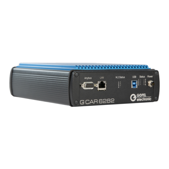
LEDs that indicate the operating status of the controller board and four additional LEDs for the M.2 status. The G CAR 6282 also has an Anybus expansion module whose DSUB-9 connector is also on the host side. 3.4.1 Block Diagram Figure 3.4 Block diagram of the G CAR 6282 Multibus Controller... - Page 18 3 Technical Description G CAR 6282...
-
Page 19: Lan/ Ethernet
The eight light-emitting diodes arranged between the USB and the voltage socket provide information about the current operating status of the G CAR 6282 Multibus Controller. LED 1 to LED 4 can assume a green or red col- or state. These LEDs can be configured by the user (green) or additionally indicate errors when they occur on the device (light up permanently red). -
Page 20: Galvanic Isolation
On the G CAR 6282 Multibus Controller, the host system is electrically isolated from the interfaces that go to the DUT. This includes the CAN/ CAN FD, LIN/ K-Line, Automotive Ethernet and FlexRay communication interfaces as well as the digital and analog inputs and outputs. -
Page 21: Onboard Interfaces
Due to the large number of possible variants, how the various bus interfaces can be connected to the transceiv- er slots some variants were defined in order to be able to handle these on the firmware side. The G CAR 6282 Multibus Controller can be equipped with these variants. -
Page 22: Can/ Can Fd
3 Technical Description 3.5.1 CAN/ CAN FD The G CAR 6282 Multibus Controller supports a total of twelve CAN/ CAN FD interfaces. For CAN and CAN FD the same transceiver is used: • TJA1044GT The following specifications apply to the transceiver: Symbol Parameter Min. -
Page 23: Flexray
3.5.3 FlexRay The G CAR 6282 Multibus Controller supports a total of two FlexRay interfaces. Since a FlexRay transceiver can map either the A or B channel, two slots are required per interface. For the total of two possible FlexRay inter- faces, a total of 4 slots are occupied. -
Page 24: Automotive Ethernet
3.6 Multi I/O Extension Board The G CAR 6282 Multibus Controller supports a total of four Digital Out interfaces onboard . These are firmly in- stalled on the board. By attaching an IO extension board, a total of 48 I/O interfaces are available (including the four onboard Digital Out interfaces). -
Page 25: Sent
3 Technical Description Symbol Parameter Min. Typ. Max. Unit Comment Digital Outputs of High Voltage version (extension board) High-level output voltage -0,2 Low-level output voltage Output current Analog Inputs (extension board) Low Voltage input voltage High Voltage input voltage Sample Rate MSPS Analog Outputs (extension board) Low Voltage output voltage... -
Page 26: 4 Software
G-API folder of the supplied "Product Information" CD 4.2 Programming via LabVIEW The supplied CD contains a VI collection that can be used to access the G CAR 6282 Multibus Controller under LabVIEW. The LabVIEW VIs use the functions of the G-API . -
Page 27: Additional Software Interfaces
4 Software UserCode programs can be downloaded and debugged directly from the Net2Run IDE via an Ethernet connec- tion. 4.4 Additional Software Interfaces 4.4.1 File System The software interface "FS" (File System) allows, among others, to create, copy, delete, run, and finding files on the hardware. -
Page 28: Reset The Device
4 Software 4.5 Reset the Device The Series 62 Multibus Controller starts automatically when the power is turned on. During operation, a software reset of the device may be performed via the API to reset the configurations to their default values. Each interface can be initialized individually or all interfaces together. To initialize an interface, the command G_Common_InitInterface can be used. -
Page 29: 5 Service And Support
5 Service and Support 5 Service and Support 5.1 Spare Parts and Accessories Item No. Designation Table 5.1 Overview spare parts and accessories Additional options for the Series 62 Multibus Controller DIAG KW2000 TP1.6 Keyword 2000 on TP1.6 onboard CAN diagnostic software DIAG KW2000 TP2.0 Keyword 2000 on TP2.0 onboard CAN diagnostic software DIAG KW2000 ISO-TP... -
Page 30: Warranty And Repair
5 Service and Support 5.2 Warranty and Repair 5.2.1 Conditions We guarantee the accuracy of the test system for a period of 24 months from the date of sale. The warranty does not apply to errors that are based on improper interventions or changes or improper use. 5.2.2 Identification Furthermore, we ask you to announce possible warranty cases as such. -
Page 31: 6 Disposal
6 Disposal 6 Disposal 6.1 Disposal of used Electrical / Electronic Equipment The device implements the following EU directives: • 2012/19/EU (WEEE) Waste Electrical and Electronic Equipment and • 2011/65/EU on the restriction of the use of certain hazardous substances in electronic equipment (RoHS directive) At the end of the life of the device, this product must not be disposed of with other household waste. - Page 32 Index Index ODU Connector, 11 Power Supply, 14 Power Adapter, 13 Power Supply, 9, 13 Product Description, 8 Accessories, 3 Addressing, 4 Analog I/O, 18 Reset, 22 Automotive Ethernet, 18 CAN/ CAN FD, 16 Safety, 2 Components, 10 SENT, 19 Sequence, 21 Software, 20 Specifications, 10 Digital I/O, 18...
Need help?
Do you have a question about the G CAR 6282 and is the answer not in the manual?
Questions and answers