Table of Contents
Advertisement
Quick Links
Advertisement
Table of Contents

Related Manuals for Gopel Electronic G PCIe

Summary of Contents for Gopel Electronic G PCIe
- Page 1 G PCIe / G PXIe / G CAR 6281 Multibus Controller Manual (Original documentation)
- Page 2 © Copyright 2021 GÖPEL electronic GmbH. All rights reserved. The software described in this manual as well as the manual itself are supplied under license and may be used or copied only in accordance with the terms of the license. The customer may make one copy of the software for safety purposes.
- Page 3 Table 1: List of changes to this document Date Editor Comment E. Richter 2.0.0 Document created in LaTex E. Richter 2.0.1 Variant G PXIe 6281 added 2021-04-30 E. Richter 2.0.2 Minimal design changes 2021-05-28 E. Richter 2.0.3 TAP Matrix added 2021-08-11 E.
-
Page 4: Table Of Contents
Firmware Update ..........Change of the Transceiver on G PCIe/ G PXIe 6281 ...... - Page 5 3.8.6 SENT ..........24 4 Software Programming via G-API .
-
Page 6: Introduction
• Flashing of control units If you use the device for any purpose for which it is not intended, the GÖPEL electronic GmbH can not be held liable for resulting damage. G PCIe / G PXIe / G CAR 6281... -
Page 7: Emc - Protection Measures
Never try to stretch cables to enable a connection. The cables must always have enough clearance. Damage caused by improper use or failure to observe the safety instructions and warnings is not covered by the warranty. For consequential damages no liability is assumed by GÖPEL electronic! G PCIe / G PXIe / G CAR 6281... -
Page 8: Liability And Warranty Exclusion
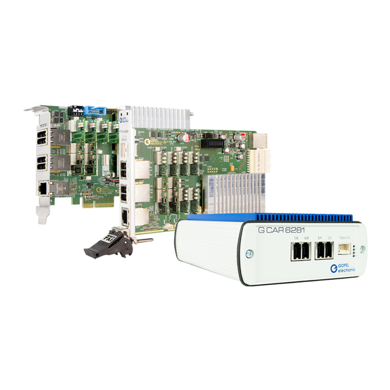
Controller 6281. 1.7 Supplied Accessories Accessories As accessories to Multibus Controller 6281 you get: • G PCIe 6281 / G PXIe 6281 plug-in card or G CAR 6281 stand-alone box • RJ45 Ethernet cable (only for G CAR 6281) •... -
Page 9: Commissioning
GÖPEL electronic GmbH 2 Commissioning 2.1 System Requirements Your system must comply with the following requirements: • At least 4-times PCIe/ PXIe slot for G PCIe/ G PXIe 6281 • At least Dual Core CPU • Windows 7 or later 2.2 Hardware Installation... -
Page 10: G Car 6281
IP address and subnet mask. Otherwise the PC / Laptop will not be able to communicate with the Multibus Controller 6281 in the network. For this setup, open the ”Properties” dialog of the corresponding network adapter and select ”Internet Protocol Version 4 (TCP / IPv4)”. G PCIe / G PXIe / G CAR 6281... - Page 11 Example: The default IP address of the Multibus Controller 6281 is 192.168.1.62 (Port 5134). For exam- ple, if you set your network device to IP address 192.168.1.1 and the subnet mask to 255.255.255.0, then both devices are now on the same subnet 192.168.1.xyz. G PCIe / G PXIe / G CAR 6281...
- Page 12 IP address. The IP address of the Multibus Controller 6281 can be changed by means of the Hardware Explorer, whereby the entered IP address only becomes effective after a successful restart. Figure 2.3: Hardware Explorer with G PCIe 6281 Multibus Controller second...
-
Page 13: Firmware Update
• Confirm after successful flashing with ”OK” 2.5 Change of the Transceiver on G PCIe/ G PXIe 6281 Independent replacement of the media interface is not intended. Please send the device to us. Arrange- ments for this can be made with our sales department. - Page 14 TRX7 and TRX8. There are two connectors per slot required for communication with the Automotive Ethernet transceivers. • Carefully insert the board into the slot again and secure it with the screw on the front panel. G PCIe / G PXIe / G CAR 6281...
-
Page 15: Technical Description
The G PCIe 6281/ G PXIe 6281 plug-in card supports PCIe up to version 2.1 and 4 lanes (4x). It has a bandwidth of 5 GBit/s per lane and a maximum transfer rate of 20 GBit/s (gross). -
Page 16: Overview Of G Pcie 6281
CHAPTER 3. TECHNICAL DESCRIPTION GÖPEL electronic GmbH 3.2 Overview of G PCIe 6281 Figure 3.1: Overview of G PCIe 6281 Table 3.1: Components of the G PCIe 6281 board Position Description LEDs/ status indication; LED1 = left .. LED4 = right (in the picture) 4x socket ”RJ.5”... -
Page 17: Overview Of G Pxie 6281
Position Description LEDs/ status indication; LED1 = left .. LED4 = right (in the picture) Socket ”DIO” 4x socket ”RJ.5” Host interface ”LAN” Slots for transceivers 6 + 7 PXIe interface G PCIe / G PXIe / G CAR 6281... -
Page 18: Overview Of G Car 6281
Figure 3.4: Overview of G CAR 6281 - Rear side Table 3.3: Components of the G CAR 6281 Position Description 4x socket ”RJ.5” Socket ”DIO” LEDs/ status indication Socket ”Power Supply” 2x socket ”SYNC” Socket ”USB” Host interface ”LAN” G PCIe / G PXIe / G CAR 6281... -
Page 19: Technical Specifications
(e.g., monitor data). On the G CAR 6281, the Ethernet interface is located on the rear side. G PCIe / G PXIe / G CAR 6281... -
Page 20: Block Diagram
Digital IN4 and Ethernet_TRX- (slots 7 + 8) Digital OUT1 Digital OUT2 Digital OUT3 Digital OUT4 Shield Figure 3.6: Numbering of the RJ.5 connectors for G PCIe 6281 and G PXIe 6281 G PCIe / G PXIe / G CAR 6281... -
Page 21: Lan/ Ethernet
The board has an RJ45 Ethernet socket for configuring and controlling the Multibus Controller 6281 using a PC. If necessary, if the board is e.g. in a rack that is only for power, this interface can act as a host interface. G PCIe / G PXIe / G CAR 6281... -
Page 22: Leds/ Status Indication
-20 .. +60 °C Power Ripple Peak to peak Weight Type of input connector IEC socket The device-side connector is a 3-pin M8 socket from PHOENIX CONTACT (Item No. 1456035; plug side: 1681172). G PCIe / G PXIe / G CAR 6281... -
Page 23: Galvanic Isolation
”SYNC right” with the right placed card. This means that the ”SYNC left” connector of one Multibus Controller 6281 is connected to ”SYNC right” of the other device. The SYNC connectors are not to be used for any purpose other than the above purpose. G PCIe / G PXIe / G CAR 6281... -
Page 24: Onboard Interfaces
ID 8 (CAN) or LIN_8 or ID 16 (LIN) or LIN_8 or ID 16 (LIN) or Ethernet_3 ID 42 Ethernet_3 ID 42 Ethernet_3 ID 42 Host Ethernet_1 ID 40 Ethernet_1 ID40 Ethernet_1 ID40 G PCIe / G PXIe / G CAR 6281... -
Page 25: Can/ Can Fd
The LIN interface is generally supplied with an internal 12 V voltage (VBAT ). If other voltage levels are used, the internal voltage of all LIN interfaces can be controlled by software with the G-API command G PCIe / G PXIe / G CAR 6281... -
Page 26: Flexray
With G_FlexRay_Node_InternalVBat_Enable the internal supply is switched on again. The 100 Ω bus terminating resistor of the transceiver can be deactivated by software with the G-API command G_FlexRay_Node_BusTermination_Disable. With G_FlexRay_Node_BusTermination_Enable the bus termination resistor is reactivated. G PCIe / G PXIe / G CAR 6281... -
Page 27: Automotive Ethernet
The following block diagram shows an overview of the TAP matrix implemented in the FPGA with the internal MII connections: G PCIe / G PXIe / G CAR 6281... -
Page 28: Digital I/O
The G PXIe 6281 plug-in card of the Multibus Controller 6281 has an additional Digital I/O connector (type Molex 501876-1040) at the front side, parallel to the connections of the RJ.5 connectors. This connector has the following pin assignment: G PCIe / G PXIe / G CAR 6281... -
Page 29: Sent
The SENT interfaces belong to the I/O interface. Therefore, they do not appear as separate interfaces in GÖPEL electronic Hardware Explorer. G PCIe / G PXIe / G CAR 6281... -
Page 30: Software
For this purpose, GÖPEL electronic has ported the existing G-API for Windows to the QNX Neutrino real-time operating system and extended it with additional onboard functionalities. The QNX Neutrino real-time operating system is based on a microkernel architecture, which is characterized by a clean separation G PCIe / G PXIe / G CAR 6281... -
Page 31: Additional Software Interfaces
Net2Run is divided into several software modules and relies heavily on AUTOSAR. There are the software modules: • • PDU Router • CAN Interface • LIN Interface • FlexRay Interface • PDU Multiplexer G PCIe / G PXIe / G CAR 6281... -
Page 32: Usercode
The reset is also possible with the HardwareExplorer. To do this, right-click on the desired device (for resetting all interfaces) in the HardwareExplorer or on a single interface and select ”Reset”. G PCIe / G PXIe / G CAR 6281... -
Page 33: Service And Support
This option is required for each Multibus Controller 6281. If necessary, please contact our sales department: GÖPEL electronic GmbH ATS-Vertrieb Goeschwitzer Str. 58 / 60 D-07745 Jena Tel.: +49-3641-6896-508 E-Mail: ats.sales@goepel.com http://www.goepel.com G PCIe / G PXIe / G CAR 6281... -
Page 34: Warranty And Repair
If necessary, please contact our support service: GÖPEL electronic GmbH ATS-Support Goeschwitzer Str. 58 / 60 D-07745 Jena Tel.: +49-3641-6896-597 E-Mail: ats.support@goepel.com http://www.goepel.com G PCIe / G PXIe / G CAR 6281... -
Page 35: Disposal
Dispose of the disposable batteries / rechargeable batteries at a recycling center for disposable batteries and rechargeable batteries. Please dispose of only discharged disposable batteries / rechargeable batteries. G PCIe / G PXIe / G CAR 6281... - Page 36 G-API, 5, Galvanic Isolation, General Electrical Specifications, Hardware Explorer, Hardware Installation, LabVIEW, LAN, 5, LED, Liability, LIN/ K-Line, Net2Run, Onboard Interfaces, Options, Pin assignment Adapter cable, DIO Connector, Power Supply, RJ.5 connector, G PCIe / G PXIe / G CAR 6281...
-
Page 37: A Appendix A Eu Declaration Of Conformity
APPENDIX A. APPENDIX A EU DECLARATION OF CONFORMITY GÖPEL electronic GmbH Appendix A EU Declaration of Conformity G PCIe / G PXIe / G CAR 6281...
Need help?
Do you have a question about the G PCIe and is the answer not in the manual?
Questions and answers