Table of Contents
Advertisement
Quick Links
PIATTAFORME AEREE SEMOVENTI
SELF-PROPELLED WORK-PLATFORMS
PLATES-FORMES DE TRAVAIL AUTOMOTRICES
SELBSTFAHRENDE HUBARBEITSBÜHNEN
PLATAFORMAS ELEVADORAS AUTOPROPULSADAS
ZELFRIJDENDE HOOGWERKERS
SERIE „XS"
XS7 E - XS8 E - XS9 E
USE AND MAINTENANCE MANUAL
- ENGLISH -
AIRO is a division of TIGIEFFE SRL
Via Villasuperiore, 82 - 42045 Luzzara (RE) ITALY -
' +39-0522-977365
-
7 +39-0522-977015
WEB: www.airo.it
037.20.UEM-EN
2010-00
Advertisement
Table of Contents

Related Manuals for Airo XS Series


Summary of Contents for Airo XS Series
- Page 1 ZELFRIJDENDE HOOGWERKERS SERIE „XS“ XS7 E - XS8 E - XS9 E USE AND MAINTENANCE MANUAL - ENGLISH - AIRO is a division of TIGIEFFE SRL Via Villasuperiore, 82 - 42045 Luzzara (RE) ITALY - ' +39-0522-977365 7 +39-0522-977015 WEB: www.airo.it 037.20.UEM-EN...
-
Page 2: Table Of Contents
Tigieffe thanks you for purchasing a product of its range, and invites you to read this manual. Here you can find all the necessary information for a correct use of the purchased machine; therefore, you are advised to follow the instructions carefully and to read the manual thoroughly. - Page 3 ....................................28 ND OF WORK 6. HANDLING AND CARRYING ..................................29 ......................................29 ANDLING ......................................30 ARRYING 6.2.1 Fold-down rails ..................................31 ..................................32 MERGENCY TOWING 7. MAINTENANCE ......................................33 ................................... 34 ACHINE CLEANING ..................................34 ENERAL MAINTENANCE 7.2.1 Various adjustments.................................. 35 7.2.2 Greasing....................................
-
Page 4: Introduction
Therefore, the description of their components, as well as control and safety systems, may include parts not present on your unit since supplied on request or not available. In order to keep pace with the technical development AIRO-Tigieffe s.r.l. reserves the right to modify the product and/or the use and maintenance manual at any time without updating the units already delivered. -
Page 5: Further Periodical Inspections
1.1.2.2 Further periodical inspections Yearly inspections are compulsory. In Italy the owner of the Aerial Platform must apply for a periodical inspection by sending a registered letter to the local competent inspection board (ASL/USL or ARPA) at least twenty days before the expiry of the year from the last inspection. -
Page 6: Description Of The Unit
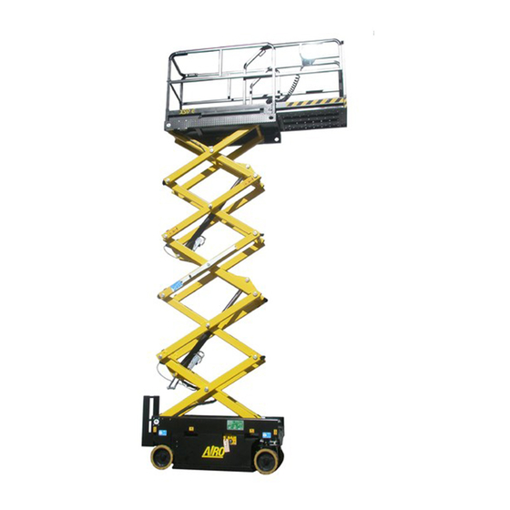
Description of the unit The machine described in this use and maintenance manual is a self-propelled aerial platform equipped with: motorized chassis equipped with wheels; vertical lifting structure, scissors type, activated by one or several hydraulic cylinders (the number of cylinders depends on the model of the machine);... -
Page 7: Identification
Identification In order to identify the machine, when spare parts and service are required, always mention the information given in the serial number plate. Should this plate (as well as the various stickers applied on the unit) be lost or illegible, it is to be replaced as soon as possible. -
Page 8: Location Of Main Components
Location of main components Below is a diagram showing the machine and its components. 1) Control panel at platform; 2) Electric power unit; 3) Hydraulic power unit; 4) Hydraulic drive engines; 5) Parking brakes; 6) 230V socket; 7) Bubble level for visual check of machine levelling;... -
Page 9: Technical Features Of Standard Machines
TECHNICAL FEATURES OF STANDARD MACHINES XS9 E Description XS7 E XS8 E “2 persons” “1 person” Max. working height – m - 6.61 7.96 9.27 Max. platform height – m - 4.61 5.96 7.27 Ground clearance (pothole guards up) – mm - Ground clearance (pothole guards down) –... - Page 10 (1) Translation with platform lifted up to the indicated limit possible only if the machine is fitted with automatic or manual pothole guards in lowered position (reduced height of the machine from the ground). Otherwise, translation is possible only with platform completely lowered (until the activation of the microswitch that automatically prevents the operation after 1 m approx.
-
Page 11: Safety Precautions
3. SAFETY PRECAUTIONS 3.1 Power supply The electrical and hydraulic circuits are provided with safety devices, calibrated and sealed by the manufacturer. Do not tamper with and modify the calibration of any component of the electrical and hydraulic system. Work and maintenance rules Always wear personal protective clothes according to current regulations concerning industrial health and safety (in particular, helmet and safety harness are COMPULSORY. -
Page 12: Safety Rules
Safety rules 3.3.1 General Only adults (full-aged persons), instructed in the use of the machine and aware of the content of this manual, should use the machine. The machine operators must always be at least two, one of them on the ground, able to carry out the emergency operations described in this manual. -
Page 13: Operating Procedures
3.3.3 Operating procedures The machine is equipped with a control load system at platform to stop lifting and lowering of the platform when it is overloaded. In case of overload with lifted platform also drive operation is prevented. Platform operation can be resumed only after removing the exceeding load. Should the audible alarm and the red warning light located on the platform control panel turn on, then the machine is overloaded (see paragraph relevant to general use instructions). - Page 14 Use and maintenance manual Self-propelled aerial platforms Page 14...
- Page 15 Use and maintenance manual Self-propelled aerial platforms Page 15...
- Page 16 Use and maintenance manual Self-propelled aerial platforms Page 16...
-
Page 17: Installation And Preliminary Checks
4. INSTALLATION AND PRELIMINARY CHECKS The machine is delivered completely assembled. No preliminary operation is required. To unload the machine, follow the instructions in paragraph “Handling and carrying”. Place the machine onto a firm ground and with a gradeability lower than the max. allowed (see “Stability limits”). The machine is equipped with platform bubble level for visual check and an inclinometer on the chassis to always check machine levelling, both transversal and longitudinal. -
Page 18: General Use Instructions
5. GENERAL USE INSTRUCTIONS Before using the machine read this chapter thoroughly. Follow exclusively the instructions given in the next paragraphs and the safety rules described both hereafter and in the previous paragraphs. Read the next paragraphs carefully in order to properly understand the on/off procedures as well as all operations and their correct use. -
Page 19: Drive And Steering
WARNING! Holding down the deadman switch for over 10 seconds without carrying out any operation will disable the control station. This condition is signalled by a flashing green LED (H). To operate the machine again it is necessary to release the deadman switch and press it again; the green LED (H) will light up steady and for the next 10 seconds all controls will be enabled. -
Page 20: Platform Lifting / Lowering
5.1.2 Platform Lifting / Lowering The controls used to lift and lower the platforms are: joystick control A; movement selector F; deadman switch N. To lift / lower the platform it is necessary to carry out the following operations in sequence: select “lifting/lowering”... -
Page 21: Manual Platform Extension (Optional)
5.1.3 Manual platform extension (optional) The mobile platform extension is carried out manually. To extend the platform it is necessary to: press the stop pedal Q; push the platform manually acting on the inclined part of the rails, holding down the pedal Q; release the pedal Q near one of the two holes according to the type of extension to be obtained;... -
Page 22: Red Warning Light: Overload (L)
5.2.5 Red warning light: overload (L) On steady and activation of audible alarm with a platform overload exceeding 30% the rated load. If the platform is lifted, the machine is completely locked. If the platform is lowered, driving/steering operations are still possible but lifting is prevented. Remove the overload before using the machine again. -
Page 23: Ground Control Station
Ground control station The ground control station is located on the chassis (see paragraph "Location of main components"). It is to be used to: turn the machine ON/OFF; select the control station (ground or platform); operate the platform in emergency situations; display some operating parameters (working hours;... -
Page 24: Hour Meter / Battery-Protection Voltmeter (A)
5.3.1 Hour meter / battery-protection voltmeter (A) The hour meter displays the working hours of the electropump (models “E”). The platform lowering takes place by gravity and does not require the activation of the electropump, so the time used for this operation is not counted by the hour meter. The function of the battery-protection Voltmeter is to prevent the battery from running down excessively. -
Page 25: Warning Light: Battery Charger (G)
with intermittent sound every 0.5 seconds to indicate the danger of entrapment in the lifting structure in the final section of the lowering operation (see par. “Platform Lifting / Lowering”). 5.3.7 Warning light: battery charger (G) The models with built-in high-frequency battery charger are provided with this warning light which signals the operation of the battery charger (for more information refer to paragraph about the battery recharge). -
Page 26: Machine Stop
Machine stop 5.6.1 Normal stop In normal operating conditions: - By releasing the controls the operation is stopped. Stop occurs within a time limit set in the factory, which guarantees smooth braking. 5.6.2 Emergency stop Should it be necessary, the operator can immediately stop all machine functions from both platform and ground control station. From the platform control station: By pressing the mushroom button on the control panel the machine is stopped. -
Page 27: Manual Emergency Lowering
Manual emergency lowering This function is to be used only in emergency situations when no motive power is available. In case of fault in the electrical or hydraulic system, for manual emergency lowering carry out the following procedure: Pull out the knob shown in the picture (for XS9 E both knobs must be pulled). -
Page 28: End Of Work
The plugs and sockets equipped on standard machines comply with EEC standards and can therefore be used in EU member countries. On request the machine can be equipped with plugs and sockets in compliance with local standards or with particular needs. -
Page 29: Handling And Carrying
6. HANDLING AND CARRYING Handling To handle the machine in normal operating conditions follow the instructions given in chapter "GENERAL USE INSTRUCTIONS" under paragraph "Drive and steering”. When the platform is completely lowered (or up to a height set according to different needs and tests) the machine can be handled (i.e. -
Page 30: Carrying
Carrying In order to carry the machine to the various working sites, follow the instructions given below. Considering the large dimensions of some models, before carrying, it is recommended to inquire about the overall dimension limits for road transport in force in your country. Before carrying the machine, turn it off and remove the key from the control panel. -
Page 31: Fold-Down Rails
6.2.1 Fold-down rails The machine is equipped with rails which can be folded down to the inside of the platform. By folding the rails down the overall height dimensions can be reduced for: transport passage through standard doors. To fold down the rails: 1) extend the mobile platform (optional) locking it into the shown position;... -
Page 32: Emergency Towing
Emergency towing In the event of a fault, carry out the following operations to tow the machine: Hook the machine to the provided holes (the same ones used for lifting – see previous pictures); Unscrew the knob A on the hydraulic block completely; Screw the knob B on the hydraulic block completely;... -
Page 33: Maintenance
The maintenance operations described hereafter refer to a machine in normal use conditions. In case of difficult use conditions (extreme temperatures, corrosive environments, etc.) it is necessary to contact AIRO Service Assistance to modify the intervention frequency. Repairs and maintenance operations are to be carried out by trained personnel only. All maintenance operations must be carried out according to current regulations as to workers safety (work places, suitable safety protections, etc.) -
Page 34: Machine Cleaning
Machine cleaning To clean the machine use non-pressurized water jets after properly protecting the following parts: the control stations (both platform and ground) all electrical boxes and electrical devices in general; the electric engines. Do not use pressurized water jets (high-pressure cleaners) to clean the machine. After washing the machine, always: dry the machine;... -
Page 35: Various Adjustments
7.2.1 Various adjustments Check the conditions of the following components and, if necessary, tighten: 1) wheel nuts; 2) wheel nut locks; 3) fixing screws of drive engines; 4) fixing screws of parking brakes; 5) steering cylinder fixing; 6) fixing screws of platforms and rails; 7) mechanical stops of mobile platform;... -
Page 36: Greasing
7.2.2 Greasing The pivot points of the lifting structure are equipped with self-lubricating bushes which are maintenance-free. At least once a month with a spatula or a brush, it is recommended to lubricate the sliding guides: a) of the sliding blocks of the extensible structure on the chassis;... -
Page 37: Hydraulic Circuit Oil Level Check And Change
7.2.3 Hydraulic circuit oil level check and change Check the level in the tank at least once a month by means of the provided plug (detail A in the picture aside) equipped with dipstick, and make sure that the level always lies between the max. and min. values;... -
Page 38: Return Filter: Replacement
7.2.4.2 Return filter: replacement The return filter A is directly flanged on the hydraulic control block. The return filter is equipped with a clogging indicator B to indicate when it needs replacing. During normal operation, the visual indicator is in the green zone. -
Page 39: Adjustment And Efficiency Check Of Inclinometer
7.2.5 Adjustment efficiency check inclinometer The inclinometer (represented in the figure in the two possible options 1 and 2) does not usually require any adjustment since it was calibrated in the factory before the delivery of the machine. This device is placed on the chassis at the centre of the lifting structure and checks the machine inclination. -
Page 40: Adjusting And Checking The Pressure Relief Valve Of The Lifting Circuit
AS THIS OPERATION IS VERY IMPORTANT IT IS TO BE CARRIED OUT BY SPECIALIZED TECHNICIANS ONLY. CALL THE TECHNICAL SUPPORT SHIMS XS7 E XS8 E XS9 E A [mm] B [mm] 7.2.6 Adjusting and checking the pressure relief valve of the lifting circuit On the self-propelled aerial platforms of the Serie XS there is a relief pressure valve on the lifting circuit to avoid dangerous overpressures. -
Page 41: Operation Check And Adjustment Of Platform Overload Controller
Operation check and adjustment of platform overload controller The AIRO self-propelled aerial platforms, Serie XS, are equipped with a sophisticated system controlling the platform overload. Normally the overload controller does not require any adjustment, since it is calibrated in the factory before the machine is delivered. - Page 42 This device checks the load on the platform and: stops all movements if platform is overloaded by 30%(*) compared to the rated load and is not in rest position; warns the user of the overload condition by means of the audible alarm and the platform warning light (see “General use rules”).
-
Page 43: Control System By-Pass
7.2.7.2 Control system by-pass. It is possible to carry out a system by-pass in the following way: locate connector A inside the central unit box; remove connection; locate connector B (by-pass), usually fixed to connector A by means of clamp; introduce connector B instead of connector A. -
Page 44: Adjusting And Efficiency Check Of Pressure Relief Valve
7.2.8 Adjusting and efficiency check of pressure relief valve The pressure relief valve controls the maximum operating pressure of driving operation. This valve does not usually need adjusting since calibrated in the workshop before the machine delivery. The calibration of the pressure relief valve is necessary: in case of replacement of the hydraulic power unit;... -
Page 45: Adjusting And Efficiency Control Of Braking Valves (Counterbalancing Valves)
7.2.9 Adjusting and efficiency control of braking valves (counterbalancing valves) These valves (in some cases only one valve is provided) check the minimum operating pressure of the drive operation (in both running directions) and influence the dynamic braking and the drive speed. These valves do not usually need any adjustment as they were previously calibrated in the workshop before the delivery of the machine. -
Page 46: Efficiency Check Of Safety Microswitches
7.2.10 Efficiency check of safety microswitches All microswitches are placed on the chassis and on the platform, and are identified by identification plates. M1-M3A-M3B Microswitch operation: M1 inserts the safety drive speed (all models enabled to drive with platform lifted) with platform at a height from the ground higher than 2 m approx.;... -
Page 47: Efficiency Check Of Control Device Of Electrical System Isolation
7.2.11 Efficiency check of control device of electrical system isolation To avoid uncontrolled movements due to accidental contacts between the poles of the battery, the casing, and an electrical actuator, a device on the chassis checks that the electrical system of the machine is isolated from the structure itself. In case of loss of one or both battery poles, this device: inhibits all movements of the machine;... -
Page 48: Dead-Man" Switch Operation Check
7.2.12 “Dead-man” switch operation check If the device works properly, no machine movement is possible from the platform control post unless you press the “dead-man” switch beforehand. If this is pressed for more than 10 seconds and no operation is performed, all movements are stopped; to operate the machine again, release the “dead-man”... -
Page 49: Battery Recharge
7.2.13.3 Battery recharge Explosive gas is originated during battery charging process; therefore, charging must take place in airy rooms where no risks of fire and explosion exist and in the presence of fire extinguishers. Connect the battery charger to the mains with the following features: Power voltage 230V ±... -
Page 50: Battery Charger: Faults Report
To use the battery charger follow these procedures: connect the battery charger by means of plug B to a 230V 50-60Hz socket equipped with all protections according to the § current standards in force; activate the main switch C (circuit breaker) and the battery charger switch H setting them to ON position; §... -
Page 51: Marks And Certifications
8. MARKS AND CERTIFICATIONS The models of self-propelled aerial platform described in this manual were subject to the CE type test according to the EEC Directive 98/37 and further modifications. The certification was issued by: IC.E.P.I. Srl Via P. Belizzi , 29/31/33 29100 Piacenza ITALIA Test carrying out is shown by the above plate with CE mark applied on the machine and by the declaration of conformity enclosed in this user manual. - Page 52 REQUIRED PERIODIC INSPECTIONS BY THE REGULATORY AGENCY Date Observations Signature + Stamp Use and maintenance manual Self-propelled aerial platforms Page 52...
- Page 53 REQUIRED PERIODIC INSPECTIONS BY THE OWNER STRUCTURAL CHECK DESCRIPTION OF OPERATIONS TO BE PERFORMED Check the integrity of the guardrails; of any access stairs; ♦ Visual check. condition of the lifting structure; rust; condition of the tyres; oil leaks; dowels of structure pins. Date Observations Signature + Stamp...
- Page 54 REQUIRED PERIODIC INSPECTIONS BY THE OWNER STRUCTURAL CHECK DESCRIPTION OF OPERATIONS TO BE PERFORMED ♦ Various adjustments. See chapter 7.2.1. Date Observations Signature + Stamp Year Year Year Year Year Year Year Year Year Year See chapter 7.2.2. Operation to be carried out every month. Its performance shall not be ♦...
- Page 55 REQUIRED PERIODIC INSPECTIONS BY THE OWNER FUNCTIONAL CHECK DESCRIPTION OF OPERATIONS TO BE PERFORMED See chapter 7.2.3. ♦ Oil level check Operation to be carried out every month. Its performance shall not be hydraulic tank. indicated every month, but at least every year together with other operations.
- Page 56 REQUIRED PERIODIC INSPECTIONS BY THE OWNER FUNCTIONAL CHECK DESCRIPTION OF OPERATIONS TO BE PERFORMED ♦ Calibration check of pressure relief See chapter 7.2.8. valve. Date Observations Signature + Stamp Year Year Year Year Year Year Year Year Year Year See chapter 7.2.12. ♦...
- Page 57 REQUIRED PERIODIC INSPECTIONS BY THE OWNER FUNCTIONAL CHECK DESCRIPTION OF OPERATIONS TO BE PERFORMED ♦ Total oil change in hydraulic tank See chapter 7.2.3. (EVERY TWO YEARS). Date Observations Signature + Stamp Year Year Year Year Year ♦ Hydraulic filters cleaning / See chapter 7.2.4.
- Page 58 REQUIRED PERIODIC INSPECTIONS BY THE OWNER SAFETY SYSTEM CHECK DESCRIPTION OF OPERATIONS TO BE PERFORMED ♦ Calibration check and operation of See chapter 7.2.5. inclinometer. Date Observations Signature + Stamp Year Year Year Year Year Year Year Year Year Year ♦...
- Page 59 REQUIRED PERIODIC INSPECTIONS BY THE OWNER SAFETY SYSTEM CHECK DESCRIPTION OF OPERATIONS TO BE PERFORMED ♦ Braking system efficiency check. See chapter 7.2.9. Date Observations Signature + Stamp Year Year Year Year Year Year Year Year Year Year Operation check of microswitches: M1, M3A+M3B (only XS9 E) ,M5, MPT1, See chapter 7.2.10 MPT2.
- Page 60 REQUIRED PERIODIC INSPECTIONS BY THE OWNER SAFETY SYSTEM CHECK DESCRIPTION OF OPERATIONS TO BE PERFORMED ♦ Check of control device of electrical See chapter 7.2.11. system isolation. Date Observations Signature + Stamp Year Year Year Year Year Year Year Year Year Year Check the legibility of the aluminium plate on the platform where the...
- Page 61 REQUIRED PERIODIC INSPECTIONS BY THE OWNER DESCRIPTION OF OPERATIONS TO BE CHECK OF EMERGENCY DEVICES PERFORMED ♦ Manual emergency controls check. See chapter 5.7. Date Observations Signature + Stamp Year Year Year Year Year Year Year Year Year Year Use and maintenance manual Self-propelled aerial platforms Page 61...
- Page 62 REQUIRED PERIODIC INSPECTIONS BY THE OWNER DESCRIPTION OF OPERATIONS TO BE SAFETY SYSTEM CHECK PERFORMED See chapter 7.12 “DEAD-MAN” SYSTEM CHECK DATE REMARKS Signature + Stamp 1° Year 2° Year 3° Year 4° Year 5° Year 6° Year 7° Year 8°...
- Page 63 Company Date Model Serial Number Date of Delivery AIRO – Tigieffe S.r.l. SUBSEQUENT TRANSFERS OF OWNERSHIP Company Date We affirm that, as of the date quoted above, the technical, dimensional and functional characteristics of this machine were in conformance with what was originally required and that any changes have been recorded in this register.
- Page 64 SUBSEQUENT TRANSFERS OF OWNERSHIP Company Date We affirm that, as of the date quoted above, the technical, dimensional and functional characteristics of this machine were in conformance with what was originally required and that any changes have been recorded in this register. The seller The Purchaser SUBSEQUENT TRANSFERS OF OWNERSHIP...
- Page 65 IMPORTANT BREAKDOWNS DATE Description of Breakdown Solution Spare Parts Used Description Code Quantity Assistance Safety Manager DATE Description of Breakdown Solution Spare Parts Used Description Code Quantity Assistance Safety Manager Use and maintenance manual Self-propelled aerial platforms Page 65...
- Page 66 IMPORTANT BREAKDOWNS DATE Description of Breakdown Solution Spare Parts Used Description Code Quantity Assistance Safety Manager DATE Description of Breakdown Solution Spare Parts Used Description Code Quantity Service Safety Manager Use and maintenance manual Self-propelled aerial platforms Page 66...
- Page 67 IMPORTANT BREAKDOWNS DATE Description of Breakdown Solution Spare Parts Used Description Code Quantity Service Safety Manager DATE Description of Breakdown Solution Spare Parts Used Description Code Quantity Service Safety Manager Use and maintenance manual Self-propelled aerial platforms Page 67...
- Page 68 IMPORTANT BREAKDOWNS DATE Description of Breakdown Solution Spare Parts Used Description Code Quantity Service Safety Manager DATE Description of Breakdown Solution Spare Parts Used Description Code Quantity Service Safety Manager Use and maintenance manual Self-propelled aerial platforms Page 68...
- Page 69 SCHEMA ELETTRICO MACCHINE STANDARD 037.08.009 - 037.08.039 INCLINOMETRO AVVISATORE ACUSTICO A TERRA AVVISATORE ACUSTICO PIATTAFORMA INDICATORE CARICABATTERIA CARABATTERIE ELETTRONICO CTRL CONTROLLER ELETTROPOMPA ELETTROPOMPA ELETTROVALVOLA MARCIA AVANTI ELETTROVALVOLA MARCIA INDIETRO ELETTROVALVOLA DI SALITA ELETTROVALVOLA DI DISCESA ELETTROVALVOLA STERZO SINISTRA ELETTROVALVOLA STERZO DESTRA EV10A ELETROVALVOLA SERIE/PARALLELO EV10B...
- Page 70 ELECTRIC DIAGRAM STANDARD MACHINES 037.08.009 - 037.08.039 INCLINOMETER GROUND AUDIBLE DEVICE PLATFORM AUDIBLE DEVICE BATTERY CHARGER INDICATOR ELECTRONIC BATTERY CHARGER CTRL ELECTROPUMP CONTROLLER ELECTROPUMP FORWARD DRIVE SOLENOID VALVE BACKWARD DRIVE SOLENOID VALVE LIFTING SOLENOID VALVE LOWERING SOLENOID VALVE LEFT STEERING SOLENOID VALVE RIGHT STEERING SOLENOID VALVE EV10A SERIES-PARALLEL SOLENOID VALVE...
- Page 71 SCHEMA ELECTRIQUE POUR MACHINES STANDARD 037.08.009 - 037.08.039 INCLINOMETRE AVERTISSEUR SONORE AU SOL AVERTISSEUR SONORE PLATE-FORME INDICATEUR CHARGEUR DE BATTERIE CHARGEUR DE BATTERIE ELECTRONIQUE CTRL CONTROLEUR ELECTRO-POMPE ELECTRO-POMPE ELECTROVANNE MARCHE AVANT ELECTROVANNE MARCHE ARRIERE ELECTROVANNE DE MONTEE ELECTROVANNE DE DESCENTE ELECTROVANNE DIRECTION GAUCHE ELECTROVANNE DIRECTION DROITE EV10A...
- Page 72 SCHALTPLAN STANDARDMASCHINEN 037.08.009 - 037.08.039 INKLINOMETER AKUSTISCHER MELDER AM BODEN AKUSTISCHER MELDER AUF DER ARBEITSBÜHNE ANZEIGER LADEGERÄT ELEKTRONISCHES LADEGERÄT CTRL STEUERUNG ELEKTROPUMPE ELEKTROPUMPE ELEKTROVENTIL VORWÄRTSGANG ELEKTROVENTIL RÜCKWÄRTSGANG ELEKTROVENTIL ANHEBUNG ELEKTROVENTIL ABSENKUNG ELEKTROVENTIL LENKUNG LINKS ELEKTROVENTIL LENKUNG RECHTS EV10A REIHEN-PARALLEL-ELEKTROVENTIL EV10B REIHEN-PARALLEL-ELEKTROVENTIL EV11 BYPASS-ELEKTROVENTIL...
- Page 73 ESQUEMA ELÉCTRICO MÁQUINAS STANDARD 037.08.009 - 037.08.039 INCLINÓMETRO AVISADOR ACÚSTICO A TIERRA AVISADOR ACÚSTICO PLATAFORMA INDICADOR DE CARGADOR DE BATERÍA CARGADOR DE BATERÍA ELECTRÓNICO CTRL CONTROLLER ELECTROBOMBA ELECTROBOMBA ELECTROVÁLVULA MARCHA ADELANTE ELECTROVÁLVULA MARCHA ATRÁS ELECTROVÁLVULA DE SUBIDA ELECTROVÁLVULA DE DESCENSO ELECTROVÁLVULA DIRECCIÓN IZQUIERDA ELECTROVÁLVULA DIRECCIÓN DERECHA EV10A...
- Page 74 ELEKTRISCH SCHEMA STANDAARD MACHINES 037.08.009 - 037.08.039 HELLINGMETER ZOEMER OP DE GROND ZOEMER OP HET PLATFORM ACCULAADMETER ELEKTRONISCHE ACCULADER CTRL BESTURING ELEKTRISCHE POMP ELEKTRISCHE POMP ELEKTROMAGNETISCHE KLEP VOORUIT RIJDEN ELEKTROMAGNETISCHE KLEP ACHTERUIT RIJDEN ELEKTROMAGNETISCHE HEFKLEP ELEKTROMAGNETISCHE DAALKLEP ELEKTROMAGNETISCHE KLEP STUURBEWEGING NAAR LINKS ELEKTROMAGNETISCHE KLEP STUURBEWEGING NAAR RECHTS EV10A ELEKTROMAGNETISCHE KLEP SERIE/PARALLEL...
- Page 75 ЭЛЕКТРИЧЕСКАЯ СХЕМА СТАНДАРТНЫХ МАШИН 037.08.009 - 037.08.039 УКЛОНОМЕР НАЗЕМНЫЙ ЗВУКОВОЙ СИГНАЛИЗАТОР ЗВУКОВОЙ СИГНАЛИЗАТОР НА ПЛАТФОРМЕ ИНДИКАТОР ЗАРЯДНОГО УСТРОЙСТВА ЭЛЕКТРОННОЕ ЗАРЯДНОЕ УСТРОЙСТВО CTRL РЕГУЛЯТОР ЭЛЕКТРОНАСОСА ЭЛЕКТРОНАСОС ЭЛЕКТРОКЛАПАН ПЕРЕДНЕГО ХОДА ЭЛЕКТРОКЛАПАН ЗАДНЕГО ХОДА ЭЛЕКТРОКЛАПАН ПОДЪЕМА ЭЛЕКТРОКЛАПАН СПУСКА ЭЛЕКТРОКЛАПАН ПОВОРОТА НАЛЕВО ЭЛЕКТРОКЛАПАН ПОВОРОТА НАПРАВО EV10A СЕРИЙНО/ПАРАЛЛЕЛЬНЫЙ...
- Page 76 Libretto uso e manutenzione Piattaforme aeree semoventi Pagina...
- Page 77 Libretto uso e manutenzione Piattaforme aeree semoventi Pagina...
- Page 78 Libretto uso e manutenzione Piattaforme aeree semoventi Pagina...
- Page 79 Libretto uso e manutenzione Piattaforme aeree semoventi Pagina...
- Page 80 Libretto uso e manutenzione Piattaforme aeree semoventi Pagina...
- Page 81 SCHEMA IDRAULICO MACCHINE STANDARD 037.07.011 SERBATOIO OLIO FILTRO CENTRALINA IDRAULICA ( 2,6+ 1,2 ) CILINDRO STERZO CILINDRO SOLLEVAMENTO GRUPPO INTEGRATO ATTACCO RAPIDO MANOMETRO FILTRO MOTORE TRAZIONE FRENO DI STAZIONAMENTO TRASDUTTORE DI PRESSIONE MOTORE ELETTRICO MANOMETRO FILTRO ELETTROVALVOLA TRAZIONE AVANTI ELETTROVALVOLA TRAZIONE INDIETRO ELETTROVALVOLA SOLLEVAMENTO ELETTROVALVOLA DISCESA ELETTROVALVOLA STERZO SINISTRA...
- Page 82 SCHEMA HYDRAULIQUE DE BASE POUR MACHINES STANDARD 037.07.011 RESERVOIR HUILE FILTRE CENTRALE HYDRAULIQUE ( 2,6+ 1,2 ) VERIN DIRECTION VERIN DE LEVEE PLATE-FORME GROUPE EV5 RACCORDEMENT MANOMETRE FILTRE MOTEURS DEPLACEMENT FREIN DE STATIONNEMENT TRANSDUCTEUR DE PRESSION MOTEUR ELECTRIQUE MANOMETRE ELECTROVANNE TRANSLATION EN AVANT ELECTROVANNE TRANSLATION EN ARRIERE ELECTROVANNE LEVEE ELECTROVANNE DESCENTE...
- Page 83 ESQUEMA IDRÁULICO MÁQUINAS STANDARD 037.07.011 DEPOSITO FILTRO CENTRAL IDRÁULICA ( 2,6+ 1,2 ) CILINDRO DIRECCIÒN CILINDRO ELEVACIÒN GRUPO INTEGRADO ENGANCHE RAPIDO MANÒMETRO FILTRO MOTOR TRACCIÒN FRENO DE ESTACIONAMIENTO TRANSDUCTOR DE PRESIÓN MOTOR ÉLÉCTRICO MANÒMETRO ELECTROVÁLVULA TRACCIÒN ADELANTE ELECTROVÁLVULA TRACCIÒN ATRÁ ELECTROVÁLVULA ELEVACIÒN ELECTROVÁLVULA DESCENSO ELECTROVÁLVULA DIRECCIÒN IZQUIERDA...
- Page 84 ГИДРАВЛИЧЕСКАЯ СХЕМА СТАНДАРТНЫХ МАШИН 037.07.011 МАСЛЯНЫЙ БАК ФИЛЬТР ГИДРАВЛИЧЕСКИЙ РАСПРЕДЕЛИТЕЛЬНЫЙ ПУЛЬТ ( 2,6+ 1,2 ) ЦИЛИНДР ПОВОРОТА ЦИЛИНДР ПОДЪЕМА РАСПРЕДЕЛИТЕЛЬ БЫСТРОЕ КРЕПЛЕНИЕ МАНОМЕТРА ФИЛЬТР ДВИГАТЕЛЬ ТЯГИ РУЧНОЙ (СТОЯНОЧНЫЙ) ТОРМОЗ ДАТЧИК ДАВЛЕНИЯ ЭЛЕКТРИЧЕСКИЙ ДВИГАТЕЛЬ МАНОМЕТР ФИЛЬТРА ЭЛЕКТРОКЛАПАН ТЯГИ ВПЕРЕД ЭЛЕКТРОКЛАПАН ТЯГИ НАЗАД ЭЛЕКТРОКЛАПАН...
- Page 85 Libretto uso e manutenzione Piattaforme aeree semoventi Pagina...
- Page 86 DICHIARAZIONE CE DI CONFORMITA' - CE DECLARATION OF CONFORMITY - DECLARATION CE DE CONFORMITE' - EG KONFORMITÄTSERKLÄRUNG - DECLARACION CE DE CONFORMIDAD- ЗАЯВЛЕНИЕ О КОНФОРМНОСТИ EC 2006/42/CE Dichiarazione originale Original Declaration Déclaration Originale Originalerklärung Declaración Original Оригинальнaя декларация Noi - We - Nous - Wir –...
- Page 87 DICHIARAZIONE CE DI CONFORMITA' - CE DECLARATION OF CONFORMITY - DECLARATION CE DE CONFORMITE' - EG KONFORMITÄTSERKLÄRUNG - DECLARACION CE DE CONFORMIDAD- ЗАЯВЛЕНИЕ О КОНФОРМНОСТИ EC 2006/42/CE Dichiarazione originale Original Declaration Déclaration Originale Originalerklärung Declaración Original Оригинальнaя декларация Noi - We - Nous - Wir –...
- Page 88 DICHIARAZIONE CE DI CONFORMITA' - CE DECLARATION OF CONFORMITY - DECLARATION CE DE CONFORMITE' - EG KONFORMITÄTSERKLÄRUNG - DECLARACION CE DE CONFORMIDAD- ЗАЯВЛЕНИЕ О КОНФОРМНОСТИ EC 2006/42/CE Dichiarazione originale Original Declaration Déclaration Originale Originalerklärung Declaración Original Оригинальнaя декларация Noi - We - Nous - Wir –...
- Page 89 AIRO è una divisione TIGIEFFE SRL Via Villasuperiore , 82 -42045 Luzzara (RE) ITALIA- ' +39-0522-977365 - 7 +39-0522-977015 WEB: www.airo.com Libretto uso e manutenzione Piattaforme aeree semoventi Pagina...
Need help?
Do you have a question about the XS Series and is the answer not in the manual?
Questions and answers