Lindab UltraLink FTCU Technical Information
Hide thumbs
Also See for UltraLink FTCU:
- Technical information (28 pages) ,
- Mounting instructions (4 pages) ,
- Mounting instruction (4 pages)

Subscribe to Our Youtube Channel
Related Manuals for Lindab UltraLink FTCU


Summary of Contents for Lindab UltraLink FTCU
- Page 1 l inda b | we si mpli fy c onst r uction Controller LindabUltraLink ® FTCU Technical information...
-
Page 2: Table Of Contents
Content Introduction ....................2 Overview ......................3 Description .....................3 Planning ......................4 Mounting ......................6 Connections ....................6 Power supply ....................8 Display ......................9 PIN-code ......................9 Settings ......................10 ID-numbers ....................14 Troubleshooting ................... 14 Maintenance ....................14 Technical data ....................15 Airflows ...................... -
Page 3: Overview
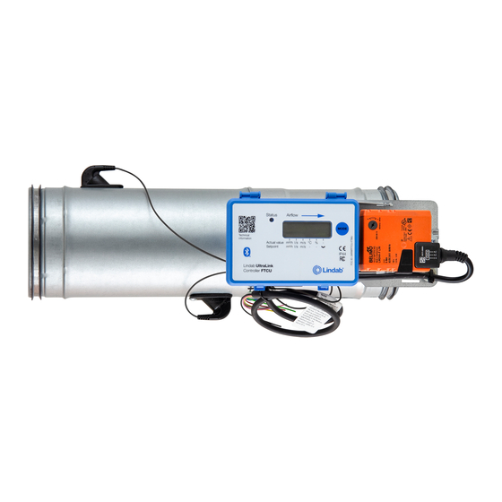
IP42 Design Lindab UltraLink Controller FTCU The Controller consists of a sensor body attached to a damper body with Lindab Safe gaskets. You are not allowed to make any changes or adjustment to the CE-mark Bluetooth ® IP classification... -
Page 4: Planning
Planning The longer distance to disturbance, i.e. the longer straight duct before the Controller, the higher the measurement accuracy will be. However this is not the only factor which affects the accuracy of the measurement. The rotation of the sensor body and hence the positioning of the first flow sensor ( in the direction of the air flow) has an impact on the uncertainty of the measure- ment. - Page 5 Measurement uncertainty ± % or X l/s depending wich is the greatest of percentage or the absolute value for the specific product size, see table “Technical data” on page 15. 2-4·Ød >4-5·Ød >5·Ød Disturbance Placement of first flow sensor Duct diameter Reducer Ød decrease...
-
Page 6: Mounting
Mounting Mount the Controller into the air duct system according to the mounting instructions for Lindab Safe. Do not use the flow sensors as handles when you mount the Control- ler since this may cause damaged and changes in their positions might influence the measurement accuracy. - Page 7 If the product is equipped with Bluetooth (the Bluetooth logotype is printed on the display unit), wireless communication with the UltraLink can be established. Using a smartphone or tablet with the Lindab UltraLink App, nearby UltraLinks can be identified. It is then possible to connect to one unit and view information regarding that UltraLink, such as active measurements and settings.
-
Page 8: Power Supply
Power supply Transformer sizing Power consumption The needed size of 24 V AC transformer(s) can be defined The power consumption for dimensioning supply cables by adding up the dimensioning power consumption [VA] for an UltraLink Controller is dependant on the size of ®... -
Page 9: Display
The arrow at the bottom of the display IP42 indicates the current parameter type and unit. Lindab UltraLink For a detailed description on configurating the UltraLink Controller FTCU using the mode button on the display, see page 13. -
Page 10: Settings
Settings All available settings are presented in the appendix. The settings can be changed via the RS485 bus and can be done from any device and configuration that can communicate using Modbus, but preferably the UltraLink Configuration tool ® (See separate documentation). If the products is equipped with Bluetooth the settings can be changed with an app, which can downloaded from Google Play or App Store. - Page 11 VALUES. SOME VALUES HAS SCALE FACTORS AND SOME VALUES OCCUPY TWO REGISTERS! Analog in settings If using analog communication (4×071=1) you need to specify the operational voltage range and also corresponding max and min values; Configure register 4×500 for analog in level configuration ( (0) 0-10V, (1) 10-0V, (2) 2-10V, (3) 10-2V) if you are using analog control of the set points.
- Page 12 Default values for the relevant registers related to “Analog Out 2” are according to the table below (Default values for flow max corresponds to 7 m/s). Size Ø 4x430 4x431 4x432 4x433 4x434 4x436 4x438 4x439 [mm] Level Unit Temp Min Temp Max Flow Min Flow Max...
- Page 13 Configuration menu structure The configuration menu is activated by long pressing the button (5 sec). After long pressing the button a new menu will appear with three different options; • Con.Set (Connection settings) • AIn.Set (Analog In settings) • Cancel (Cancel and return to information menu) You can toggle between the three options by short pressing the button.
-
Page 14: Id-Numbers
IP42 will be displayed. If communication fails, please verify the following before contacting support: Lindab UltraLink Controller • Check settings for Baud rate, parity and stop bit and make sure the master uses the same settings as the UltraLinks. -
Page 15: Technical Data
Technical data Power supply 24 (18—32) V 24 (24—28) V Cable Max outer diameter 7 mm Power consumption Dim. 100 - 315 Dim. 400 - 630 Power consumption For wiring, dim. 100 - 315 3 VA For wiring, dim. 400 - 630 5 VA IP class Tightness class to the environment... -
Page 16: Appendix A - Modbus Register
Appendix A – Modbus register Address : Modbus register address (3x indicates Input & 4x indicates Holding) UltraLink Type of UltraLink where the register is available (Indicated by “x”) ® ® Name: Name of register Description: Short description of register. Data type: Data type for register (16bit contained in one register, 32bit and float in two consecutive registers) . - Page 17 UltraLink ® Name Description HOLDING REGISTERS Communication settings 4x001 Communication id Modbus address 16bit 4x002 RS485 Baud Rate Conf. Baudrate: 16bit 0 = 9600 1 = 19200 2 = 38400 3 = 76800 4x003 RS485 Parity Conf. Parity: 16bit 0 = Odd; 1 = Even;...
- Page 18 UltraLink ® Name Description 4x315 Flow Set Point Minimum Flow setpoint min. 16bit 4700 4x316 Flow Set Point Maximum Flow setpoint max. 16bit 4700 Analog output 4x400 Analog Output 1 Level Analog output config: 16bit Conf. 0 = 0-10 V, 1 = 10-0 V, 2 = 2-10 V, 3 = 10-2 V.
- Page 19 UltraLink ® Name Description Analog input (Settings below are only relevant when register 4x071 is set to 1) 4x500 Analog In Level Conf. Analog input: 16bit 0 = 0-10 V, 1 = 10-0 V, 2 = 2-10 V, 3 = 10-2 V. 4x501 Analog In Angle Minimum Min angle = min voltage...
- Page 20 At Lindab, good thinking is a philosophy that gui- des us in everything we do. We have made it our mission to create a healthy indoor climate – and to simplify the construction of sustainable buil- dings. We do that by designing innovative pro- ducts and solutions that are easy to use, as well as offering efficient availability and logistics.
Need help?
Do you have a question about the UltraLink FTCU and is the answer not in the manual?
Questions and answers