Table of Contents
Advertisement
User Guide
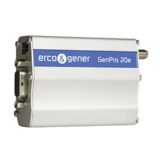
GenPro 20e
Reference : EG_GenProxxe_988_UG_008_UK
Revision :
Date :
S.A. ERCO & GENER – ZI de St. Lambert-des-Levées – BP 30163 – F-49412 SAUMUR Cedex
Tél. : +33 (0)2 41 83 13 00 – Fax : +33 (0)2 41 67 19 20 – www.ercogener.com – infos@ercogener.com
€
SA CAPITAL 200873
– R.C. SAUMUR B 332 174 820 – SIRET 332 174 820 00032 – NAF 322A – TVA Intra : FR 16 332 174 820
GenPro 24e
008
24/06/2011
L'esprit Modem
Advertisement
Table of Contents

Related Manuals for Erco & Gener GenPro 20e


Summary of Contents for Erco & Gener GenPro 20e
- Page 1 L’esprit Modem User Guide GenPro 20e GenPro 24e Reference : EG_GenProxxe_988_UG_008_UK Revision : Date : 24/06/2011 S.A. ERCO & GENER – ZI de St. Lambert-des-Levées – BP 30163 – F-49412 SAUMUR Cedex Tél. : +33 (0)2 41 83 13 00 – Fax : +33 (0)2 41 67 19 20 – www.ercogener.com – infos@ercogener.com €...
- Page 2 EG_GenProxxe_988_UG_008_UK Page 2 / 51 Document history Revision Modifications Author Date F. LE BRETON CREATION (Version UK) 09/11/06 M. REEVES Modified schema 2-wire cable page 16. F. LE BRETON 20/02/07 Added Hardware WatchDog function page 11-30-35. Checked functionnal architecture page 30. F.
-
Page 3: Table Of Contents
EG_GenProxxe_988_UG_008_UK Page 3 / 51 CONTENTS PRESENTATION ............................... 5 WARNING ................................. 6 COPYRIGHT AND DISCLAIMER ........................6 1 REFERENCES ............................... 7 1.1 Product Differences ............................. 7 1.2 Reference Documents ..........................8 1.3 Abreviations ..............................8 ... - Page 4 EG_GenProxxe_988_UG_008_UK Page 4 / 51 7.5 BOOT ................................. 34 7.6 RESET ............................... 34 7.6.1 General ............................34 7.6.2 RESET sequence .......................... 34 7.7 WatchDog ..............................35 7.8 Audio ................................35 7.8.1 Microphone ............................ 35 ...
-
Page 5: Presentation
This product also conforms to the automotive standards (“E” label). The GenPro modem is Bi-Band 900/1800 MHz (please consult for the Quad-Band version 850/900/1800/1900 MHz) and GSM or GSM/GPRS Class 10. It is available in two versions: GenPro 20e and GenPro 24e (see Product Differences table). -
Page 6: Warning
ERCO & GENER is strictly prohibited. GenPro 20e and GenPro 24e are trademarks of ERCO & GENER. Hayes is a registered trademark of Hayes Microcomputer Product Inc. The names of products and companies mentioned in this document may be names or trademarks of their respective holders. -
Page 7: References
EG_GenProxxe_988_UG_008_UK Page 7 / 51 1 References 1.1 Product Differences The various features of the GenPro product range are show in the Product differences table below: GenPro 2xe Modem GSM Features - E-GSM Bi-Band 900/1800 MHz – Quad-Band 850/900/1800/1900 MHz (*) - ETSI GSM Phase 2+ Class 4 (2W @ 850 / 900 MHz) Class 1 (1W @ 1800 / 1900 MHz) -
Page 8: Reference Documents
EG_GenProxxe_988_UG_008_UK Page 8 / 51 1.2 Reference Documents Wavecom AT Commands Interface Guide: P_AT_Commands_Interface_Guide_for_Xxxx_Appendix_revyyy Software update procedure: EG_GenProxxe_988_UP_000_UK GSM reference documents: ● GSM 07.05. ● GSM 07.07. 1.3 Abreviations Alternative Current Accumulated Call Meter Attention (prefix for modem commands) Base Transceiver Station ClocK CMOS Complementary Metal Oxide Semiconductor... - Page 9 EG_GenProxxe_988_UG_008_UK Page 9 / 51 Light Emitting Diode MAXimum Mobile Equipment MICrophone Family of connectors from Molex Micro FIT MINimum Microcom Networking Protocol Mobile Originated Mobile Station Mobile Terminated NOMinal Output Pascal (for speaker sound pressure measurements) PBCCH Packet Broadcast Control Channel Personal Computer Power Control Level Packet Data Protocol...
-
Page 10: Packing
EG_GenProxxe_988_UG_008_UK Page 10 / 51 2 Packing 2.1 Contents The GenPro is supplied with: - GenPro packing case, - GenPro modem, - 2 fixing brackets, - Instructions Sheet. - 4-wire cable (Red/Black/Orange/Green) with in-line fuse (depending on GenPro), - 2-wire cable (Red/Black) with in-line fuse (depending on GenPro), - 2-wire cable (Blue/Yellow) (depending on GenPro). -
Page 11: Packing Case
EG_GenProxxe_988_UG_008_UK Page 11 / 51 2.2 Packing Case Packing case external dimensions: - Width: 54.5 mm, - Height: 68 mm, - Length: 108 mm. An identification label is attached to the top of the packing case. It contains - The ERCO & GENER logo, - The product reference (GenPro xxe), - CE mark, - Hardware WatchDog mark,... -
Page 12: General Presentation
EG_GenProxxe_988_UG_008_UK Page 12 / 51 3 General Presentation 3.1 Physical Description Description of the GenPro 2xe modem: Connector Connector Micro-Fit 2-pins/M Micro-Fit 4-pins/M (only on GenPro 24e) Front side Connector Sub HD 15-pins/F Rear side Connector SMA/F (GSM antenna) GSM LED SIM card cover Two fixing brackets for attaching the modem to a support: Fixing brackets... -
Page 13: External Connections
EG_GenProxxe_988_UG_008_UK Page 13 / 51 3.2 External connections 3.2.1 Connections 3.2.1.1 GSM antenna connector The GSM antenna connector is a 50Ω impedance female SMA type. 3.2.1.2 Micro FIT connectors 4-pin Micro FIT female connector: This connector allows the connection of an external DC supply, and provides one general-purpose input and one general-purpose output. -
Page 14: 15-Pin Sub Hd Female Connector
EG_GenProxxe_988_UG_008_UK Page 14 / 51 3.2.1.3 15-pin Sub HD female connector This connector provides: - The serial RS232 link, - The audio line connection (microphone and loud-speaker), - The BOOT and RESET signals. Pin N° Description Circuit (V24 – RS232C) Signal detection / Buzzer 109 –... -
Page 15: Cables
EG_GenProxxe_988_UG_008_UK Page 15 / 51 3.2.2 Cables Depending on the GenPro ordered, the different cables described below will be supplied (refer to the Product Differences table). 3.2.2.1 4-wire micro FIT supply cable This cable provides power to the modem. Component Characteristics 4-pin Micro FIT connector Type : MOLEX... -
Page 16: 2-Wire Micro Fit Inputs Cable
EG_GenProxxe_988_UG_008_UK Page 16 / 51 3.2.2.3 2-wire micro FIT inputs cable This cable provides access to two general-purpose inputs. Component Characteristics 2-pin Micro FIT connector Type : MOLEX Cable Length ≈ 1.5m Wire Tinned copper 24 x 0.2 mm Descriptions and non-contractual illustrations in this document are given as an indication only. ERCO&GENER reserves the right to make any modifications. -
Page 17: Characteristics And Services
EG_GenProxxe_988_UG_008_UK Page 17 / 51 4 Characteristics And Services The GenPro is a class 10 GSM or GSM/GPRS modem intended for asynchronous binary data transmission, fax Group3 (Class 2), SMS and voice. It also has 3 general purpose inputs and 1 output. The characteristics of the different GenPro are shown in the Product Differences table. -
Page 18: Using The Modem
EG_GenProxxe_988_UG_008_UK Page 18 / 51 5 Using The Modem 5.1 Starting with the modem 5.1.1 Mounting the modem To mount the modem on a support, use the fixing brackets as shown in the diagram below: Note : - Must be fixed to a flat surface. -
Page 19: Communication With The Modem
EG_GenProxxe_988_UG_008_UK Page 19 / 51 5.1.3 Communication with the modem Connect the RS232 cable between the DTE (the COM port) and the modem (DCE). Configure the DTE RS232 port as follows : ▪ Data rate : 9600 bps, ▪ Data size : 8 bits, ▪... -
Page 20: Recommendations For Using The Modem In Vehicles
EG_GenProxxe_988_UG_008_UK Page 20 / 51 5.2 Recommendations for using the modem in vehicles WARNING : The power supply connector on the GenPro must NOT be connected directly to the battery of a vehicle. 5.2.1 Recommended connection to the battery in a lorry All lorries have a circuit breaker outside the cabin. -
Page 21: Technical Constraints In Lorries
EG_GenProxxe_988_UG_008_UK Page 21 / 51 5.2.2 Technical constraints in lorries It is highly recommended to NOT connect the modem supply directly the battery but instead to the circuit breaker. Otherwise the modem may be damaged when the lorry is starting and the circuit breaker is closed. In this case the ground of the lorry and the ground of the battery will be connected together via the modem as shown in the diagram below: Example of a... -
Page 22: Gsm Indicator Led
EG_GenProxxe_988_UG_008_UK Page 22 / 51 5.3 GSM indicator LED The state of the modem is indicated by the GSM LED located on the rear side of the modem (see chapter 3.1 Physical Description). The table below shows the meaning of the different states of the GSM LED : GSM LED LED activity Modem state... -
Page 23: Verifying Gsm Receive Signal Quality
EG_GenProxxe_988_UG_008_UK Page 23 / 51 5.5 Verifying GSM receive signal quality The modem will be able to establish a call only if the received GSM signal is of a sufficient level. The command AT+CSQ will return the reception level (rssi) of the signal sent by the closest GSM Base Transceiver Station (BTS), as well the receive bit error rate (ber). -
Page 24: Verifying The Pin Code
EG_GenProxxe_988_UG_008_UK Page 24 / 51 5.6 Verifying the PIN code The PIN code is essential in order to make a call or to accept a call from the GSM network. The PIN code is held on the SIM card and can be modified by the user. To verify a previously entered PIN code, use a communication application and enter the command AT+CPIN? The table below shows the main responses from the modem :... -
Page 25: Main At Commands (Hayes)
EG_GenProxxe_988_UG_008_UK Page 25 / 51 5.8 Main AT commands (HAYES) The table below shows at a quick glance the main AT commands useful for the control of the modem. For further information concerning the complete command set see the Wavecom "AT Commands Interface Guide"... -
Page 26: Powering Down The Unit
EG_GenProxxe_988_UG_008_UK Page 26 / 51 5.9 Powering down the unit It is strongly unadvised to cut off the supply of GenPro whilst in communication or dialogue without having first detached from the network operator. To avoid network congestion when powering down the modem, it is essential to first execute the command AT+CPOF. -
Page 27: Trouble Shooting
EG_GenProxxe_988_UG_008_UK Page 27 / 51 6 Trouble Shooting This section describes various problems and their solutions that may be encountered when using the modem. Please consult the review on other problems in the FAQ’s on our web site in Support > FAQ. 6.1 RS232 (V24) Communication problem If the modem does not respond to any of the AT commands via the RS232 then refer to the table below for a list of possible causes and solutions. -
Page 28: Carrier" Message
EG_GenProxxe_988_UG_008_UK Page 28 / 51 Enter the command AT+CMEE=1 to obtain an error message with its error code instead of a simple “ERROR” message, Enter again the AT command which previously caused a problem to obtain the error code. In the case of an error, the response is in the form : +CME ERROR : <error code>, or +CMS ERROR : <error code>. - Page 29 EG_GenProxxe_988_UG_008_UK Page 29 / 51 Table : Interpretation of extended error codes Error code Meaning Observations Unassigned (unallocated) number Normal call clearing User busy No user responding User alerting, no answer Call rejected Number changed Normal, unspecified Check your subscription (data subscription Requested facility not subscribed available?).
-
Page 30: Functional Description
EG_GenProxxe_988_UG_008_UK Page 30 / 51 7 Functional Description 7.1 Architecture Descriptions and non-contractual illustrations in this document are given as an indication only. ERCO&GENER reserves the right to make any modifications. -
Page 31: Power Supply
EG_GenProxxe_988_UG_008_UK Page 31 / 51 7.2 Power supply 7.2.1 General The modem must be powered (V+BATTERY) by an external regulated DC power source of between 5.5V and 32V. The modem’s various internal DC voltages are provided by an internal DC/DC converter. The correct functioning of the modem cannot be guaranteed if the input voltage (V+BATTERY) falls below 5.5V. -
Page 32: Rs232 Serial Link
EG_GenProxxe_988_UG_008_UK Page 32 / 51 7.3 RS232 serial link 7.3.1 General The RS232 interface provides a level translation between the WISMO (DCE) and the PC COM port (DTE). The RS232 interface is protected internally (ESD protection) against external electrostatic spikes. Filter guarantees : Input/output EMI/RFI protection, Signal smoothing. -
Page 33: Auto-Baud Mode
Only the Gen Pro 24e modems is equipped with 3 opto-coupled inputs and 1 open-collector output for external use (please consult us). The modem GenPro 20e is not equipped with GPIO’s see Product Differences table). The shock detector is pre-assembled option which must be requested when ordering. -
Page 34: Boot
EG_GenProxxe_988_UG_008_UK Page 34 / 51 7.5 BOOT This signal must not be connected. Its use is strictly reserved by the manufacturer. 7.6 RESET 7.6.1 General A low level input on this pin allows a forced emergency hardware RESET of the modem (see the chapter 7.6.2 RESET sequence below). -
Page 35: Watchdog
EG_GenProxxe_988_UG_008_UK Page 35 / 51 7.7 WatchDog The Hardware WatchDog function allows the surveillance of the modem software activity: the Software management of the WatchDog must be implanted in the embedded application (Open AT). If the software activity is interrupted, the component WatchDog starts a material Reset. The WatchDog function is active only if the SIM card is present. -
Page 36: Loud-Speaker
EG_GenProxxe_988_UG_008_UK Page 36 / 51 The gain of the microphone input may be internally adjusted in 3dB steps to between +30dB to +51dB by using the command AT+VGT (see the Wavecom “AT Commands Interface Guide”). Table : Pins description Pin number Sub HD Signal name Type Description... - Page 37 EG_GenProxxe_988_UG_008_UK Page 37 / 51 Syntax: AT+ WTONE =<mode>,<dest>,<freq>,<gain>,<duration> <mode> 0 : stop the tone 1 : generate a tone <dest> : Select the output 1 : Speaker (Loud-speaker) 2 : Buzzer <freq> : Frequency of the tone for the Speaker, the range is 300Hz to 3400Hz for the Buzzer, the range is de 1Hz to 50000Hz <gain>...
-
Page 38: Technical Characteristics
EG_GenProxxe_988_UG_008_UK Page 38 / 51 8 Technical Characteristics 8.1 Mechanical Table : Mechanical characteristics Dimensions 73 x 54.5 x 25.5 mm (excluding connectors) Overall Dimensions 90 x 54.5 x 25.5 mm ≈ 95 grams (modem only) Weight < 197 grams (modem + fixing brackets + cables) Volume 101.5 cm³... -
Page 39: Electrical
EG_GenProxxe_988_UG_008_UK Page 39 / 51 8.2 Electrical 8.2.1 Power supply Table : Voltage range and power consumptions Operating voltage range 5.5V to 32V DC (GSM or DCS or GPRS) - GSM 900 MHz : 105mA @ 12V in communication Average power consumptions - GSM 1800 MHz : 80mA @ 12V in communication Note : The modem is permanently powered once the power supply is connected. -
Page 40: Audio Interface
EG_GenProxxe_988_UG_008_UK Page 40 / 51 8.2.2 Audio interface The audio interface is accessible via the 15-pin Sub HD connector (see chapter 7.7 Audio). 8.2.2.1 Microphone and Loud-speaker Table : Characteristics of the audio interface on the 15-pin Sub HD connector Audio parameters Min. -
Page 41: Buzzer Option
EG_GenProxxe_988_UG_008_UK Page 41 / 51 8.2.2.2 Buzzer option Audio parameters Max. Units Loud Speaker output current (max.) Command voltage VCE Table: Example of a transducer tested with the GenPro : Buzzer characteristics Values Type Transducer KINGSTATE KX-1612 Power consumption 6-18V peak/40mA max. Resonant frequency 2400Hz ±200HZ Coil impedance... -
Page 42: General Purpose Inputs / Output
EG_GenProxxe_988_UG_008_UK Page 42 / 51 8.2.4 General purpose inputs / output The GenPro 24e modem provide 3 opto-coupled inputs (E1, E2 and E3) and 1 open-collector output (S1). 8.2.4.1 Inputs Table : Characteristics of the inputs (diode of opto-coupler) Caractéristiques Symboles Conditions Min. -
Page 43: Output
EG_GenProxxe_988_UG_008_UK Page 43 / 51 8.2.4.2 Output Table : Characteristics of the open-collector output Caractéristiques Symboles Conditions Max. Unité Tension max. Emetteur ouvert Tension max. = 0 V Courant collecteur Tension saturation = 500 mA CEsat Dissipation ≤ 25 °C, T = 110 °C 0.78 Ttot... -
Page 44: Gsm/Dcs
EG_GenProxxe_988_UG_008_UK Page 44 / 51 Table : RESET signal operating conditions Parameters Min. Max. Condition 1.1 V 1.2 V 1.7 V 1.9 V 0.4 V = -50 µA 2.0 V 2.8 V = 50 µA Hysteresis thresholds 8.2.6 GSM/DCS 8.2.6.1 Frequency bands Table : Frequency ranges Parameter E-GSM 900... -
Page 45: Rf Performances
EG_GenProxxe_988_UG_008_UK Page 45 / 51 8.2.6.2 RF Performances The RF performances are compliant with the ETSI GSM 05.05 recommendation. The RF performances for receiver and transmitter are given in the table below. Table : Receiver and Transmitter RF performances Receiver E-GSM900 Reference Sensitivity E-GSM900 Reference Sensitivity GSM/DCS1800 Reference Sensitivity... -
Page 46: Environmental Characteristics
EG_GenProxxe_988_UG_008_UK Page 46 / 51 8.3 Environmental characteristics To ensure the correct operation of the modem, the limits listed in the table below should be respected. Table : Environmental characteristics Operating temperature -20 °C to +55 °C Storage temperature -30 °C to +85 °C Operating humidity without condensation HR <... -
Page 47: Protections
EG_GenProxxe_988_UG_008_UK Page 47 / 51 8.5 Protections 8.5.1 Power supply The modem is protected by an in-line fuse in the power supply cable supplied with the modem. The fuse type is : FSD 2.5 A / 250 V FAST. 8.5.2 Over-voltage The modem is protected against voltages over +32 VDC. -
Page 48: Security Recommendations
EG_GenProxxe_988_UG_008_UK Page 48 / 51 9 Security Recommendations 9.1 General It is important to follow the specific regulations for the use of radio operator equipment, in particular the possible risks of radio frequency interference (RFI). Please follow carefully the security advice given below. Turn off your GSM modem : •... -
Page 49: Security In A Vehicle
EG_GenProxxe_988_UG_008_UK Page 49 / 51 9.2 Security in a vehicle Do not use your GSM modem whilst driving a vehicle, unless equipped with a correctly installed ear- piece/hands-free kit. Respect the national regulations for the use of cellular telephones in vehicles. Road safety is always a priority. -
Page 50: Recommended Accessories
EG_GenProxxe_988_UG_008_UK Page 50 / 51 10 Recommended Accessories The accessories recommended by ERCO & GENER for use with the GenPro modem are shown on our Internet site in the section Products > Accessories. For more information, contact our sales department. 11 Client support ERCO &... -
Page 51: Declaration Of Conformity
Rue des Petites Granges Z.I. de Saint Lambert des Levées B.P. 30163 49412 SAUMUR CEDEX – France Website : http://www.ercogener.com declares that the products : Name : GenPro 20e Type : Modem Name : GenPro 24e Type : Modem Complies with : - R&TTE 1999/5/EC Directive,...
Need help?
Do you have a question about the GenPro 20e and is the answer not in the manual?
Questions and answers