
Related Manuals for DTS TDAS G5

Summary of Contents for DTS TDAS G5
- Page 1 TDAS G5 Data Acquisition System User’s Manual October 2019 11000-00010-MAN (Rev. 5) © Diversified Technical Systems, Inc. - All Rights Reserved...
-
Page 2: Table Of Contents
™ and TDAS G5 Docking Stations ............12 Appendix A: TDAS G5 DAS 216-position Interface Connector ....... 14 Appendix B: Mechanical Specifications ............15 Appendix C: Changing the TDAS G5 DAS Network Parameters ..... 16 Establish Communication ................16 Change the Network Parameters ..............16 Using the New Settings .................. -
Page 3: Dts Support
DTS has support engineers worldwide with extensive product knowledge and test experience ready to help via telephone, e-mail or on-site visits. The best way to contact a DTS support engineer is to submit a request through the DTS Help... -
Page 4: Overview Of Tdas G5 Das Features
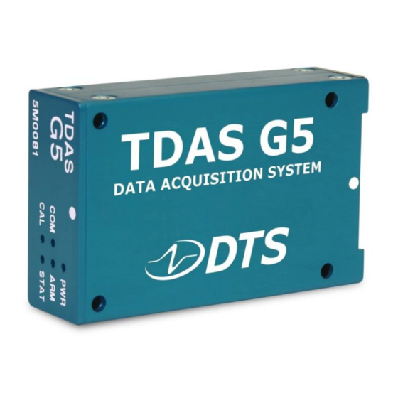
Each TDAS G5 Data Acquisition System (DAS) is a standalone, 32-channel, data acqui- sition system. This manual discusses the features and options available with the TDAS G5 DAS. To identify the specific hardware included with your system, please see your packing list. Overview of TDAS G5 DAS Features •... -
Page 5: Shunt Calibration Resistors
2004-2019 © Diversified Technical Systems, Inc. - All Rights Reserved Sensor Connections Shunt Calibration Resistors Conventional shunt calibration resistors are not supported in the TDAS G5 DAS. Shunt emulation is used to perform shunt checks. Shunt Emulation The TDAS G5 DAS uses shunt emulation to perform shunt checks. Shunt emulation eliminates the need for conventional shunt resistors and is enabled when “Emulation”... -
Page 6: Hardware Filters
Sensor Information File (SIF). Memory Size Each TDAS G5 DAS contains 5 MB of non-volatile flash memory and 100 MB of volatile RAM. For each sensor channel, the maximum samples available via flash memory is 10k samples/second for 7 seconds;... -
Page 7: Tdas G5 Das Interface Connector
October 2019 TDAS G5 DAS Interface Connector All functions and signals enter and exit the TDAS G5 DAS via the gold-plated, 216- position interface connector panel. The connector panel should be treated with great care as any debris, solvents, or oil (even from fingers), can compromise the integrity of the connections/signals. -
Page 8: Basic Care And Handling
All vehicle-/sled-mounted systems are rated for and fully tested to 100 g, 12 msec duration, in all axes. TDAS G5 equip- ment can be mounted directly on a vehicle, sled or other dynamic testing device. -
Page 9: Thermal Considerations
Most implementation scenarios use one of the two available TDAS G5 docking stations, either of which provide an adequate heat sink under normal operating conditions. If two or more of the above factors will cause case temperatures in excess of 50°C, the airflow created by a small... -
Page 10: Power Considerations
TDAS G5 DAS de-energizes several circuits to minimize power consumption. It takes a maximum of 125 seconds (for 70 seconds of data at 10k samples/second) after the end of the data storage window for the TDAS G5 DAS to return to the idle state, which then allows communication and download. -
Page 11: Communication Features
Communication is enabled after the power-up sequence has completed (~20 seconds). (See Appendix D for the network parameters of your equipment.) LED Indicators The TDAS G5 DAS has five LEDs (red/yellow/green) which provide ongoing status information. LED behavior is summarized in the table below. COM: Provides communication status with the docking station and DAS. -
Page 12: Application Support Equipment
Application Support Equipment iDummy ™ and TDAS G5 Docking Stations The most common method of using a TDAS G5 DAS is within a docking station. Two ™ types of docking stations are available: in-dummy (iDummy ) and on-vehicle (TDAS G5 Docking Station). TDAS G5 DAS units can be moved from in-dummy to on-vehicle applications as needed. - Page 13 32 LEMO connectors On-vehicle Docking Station The TDAS G5 Docking Station allows for easy installation and removal of the TDAS G5 DAS into a rugged enclosure useful for on-board testing applications. Power, commu- nication and event signals are easily accessible via the control panel. A variety of larger sensor connectors, such as LEMO 1B or equivalent, can be easily connected via a compact sensor connector panel.
-
Page 14: Appendix A: Tdas G5 Das 216-Position Interface Connector
TDAS G5 DAS User’s Manual October 2019 Appendix A: TDAS G5 DAS 216-position Interface Connector support.dtsweb.com 11000-00010-MAN (Rev. 5) -
Page 15: Appendix B: Mechanical Specifications
TDAS G5 DAS User’s Manual October 2019 Appendix B: Mechanical Specifications Weight: 200 grams 3.374 inches/85.7 mm 0.472 inches 2.677 inches/68 mm 12 mm 0.984 inches 25 mm 1.732 inches 44 mm 0.158 inches diam 0.197 inches 4.0 mm diam... -
Page 16: Appendix C: Changing The Tdas G5 Das Network Parameters
Appendix C: Changing the TDAS G5 DAS Network Parameters TDAS G5 systems communicate using the industry-standard Ethernet protocol. Your TDAS G5 DAS was shipped with fixed IP address (myip) and subnet mask (netmask) parameters already loaded in the flash memory of the microcontroller. The steps below describe the process to change the DAS unit’s Ethernet parameters. - Page 17 TDAS G5 DAS User’s Manual October 2019 The following commands are used to read and set the network parameters: fpget – Get parameter (print parameter from flash memory) Command fpget <name> - read parameter fpset – Set parameter (set parameter into flash memory) Command fpset <name>...
-
Page 18: Using The New Settings
6. Confirm your computer’s Windows/network settings match the new TDAS G5 network parameter(s). If changes are required to your computer, please contact your network administrator for assistance. 7. Start the TDAS Control software and confirm that the TDAS G5 DAS is found at the new IP address. support.dtsweb.com... -
Page 19: Appendix D: Hardware Configuration Specifications
October 2019 Appendix D: Hardware Configuration Specifications TDAS G5 DAS ship from the factory with the default IP address shown on the packing list for the equipment. If the packing list is not available and you need information on the specifics of your equipment, please submit a request through the DTS Help Center web portal (support.dtsweb.com) and include the serial number(s) of the equipment and... - Page 20 28 Oct 2019 Corrected unit of measure for sampling rate and updated lower limit (page 4). Moved TDAS G5 DAS Interface Connector section. Updated Appendix D, DTS Support boilerplate and support link in footer. Removed HQ address. (Rev 5) 04 Dec 2013 Updated DTS Support, Input Range, Hardware Filters and Memory Size sections.
Need help?
Do you have a question about the TDAS G5 and is the answer not in the manual?
Questions and answers