Table of Contents
Advertisement
In interests of user-safety the oven should be restored to its original condition and only parts identical to those specified
should be used.
BEFORE SERVICING - - - - - - - - - - - - - - - - - - - - - - - - - - - - - - - - - - - - - - - - - - - - - - - - - - - - - - - - - - - - - - - - -2
WARNING TO SERVICE PERSONNEL - - - - - - - - - - - - - - - - - - - - - - - - - - - - - - - - - - - - - - - - - - - - - - - - - - - - -3
PRECAUTIONS FOR USING LEAD -FREE SOLDER - - - - - - - - - - - - - - - - - - - - - - - - - - - - - - - - - - - - - - - - - - -4
PRODUCT SPECIFICATIONS - - - - - - - - - - - - - - - - - - - - - - - - - - - - - - - - - - - - - - - - - - - - - - - - - - - - - - - - - - -5
GENERAL INFORMATION - - - - - - - - - - - - - - - - - - - - - - - - - - - - - - - - - - - - - - - - - - - - - - - - - - - - - - - - - - - - - -6
TEST PROCEDURES - - - - - - - - - - - - - - - - - - - - - - - - - - - - - - - - - - - - - - - - - - - - - - - - - - - - - - - - - - - - - - - - -7
WIRING - - - - - - - - - - - - - - - - - - - - - - - - - - - - - - - - - - - - - - - - - - - - - - - - - - - - - - - - - - - - - - - - - - - - - - - - - - -9
CIRUITS - - - - - - - - - - - - - - - - - - - - - - - - - - - - - - - - - - - - - - - - - - - - - - - - - - - - - - - - - - - - - - - - - - - - - - - - - - 23
TROUBLESHOOTING - - - - - - - - - - - - - - - - - - - - - - - - - - - - - - - - - - - - - - - - - - - - - - - - - - - - - - - - - - - - - - - - 27
TEST MODE AND INPUT CURRENT ADJUSTMENT - - - - - - - - - - - - - - - - - - - - - - - - - - - - - - - - - - - - - - - - - - 33
SERVICE COUNTERS - - - - - - - - - - - - - - - - - - - - - - - - - - - - - - - - - - - - - - - - - - - - - - - - - - - - - - - - - - - - - - - - 36
COMPONENT REPLACEMENT AND ADJUSTMENT PROCEDURE - - - - - - - - - - - - - - - - - - - - - - - - - - - - - - - 39
SERVICE INFORMATION - - - - - - - - - - - - - - - - - - - - - - - - - - - - - - - - - - - - - - - - - - - - - - - - - - - - - - - - - - - - - 63
MICROWAVE MEASUREMENT - - - - - - - - - - - - - - - - - - - - - - - - - - - - - - - - - - - - - - - - - - - - - - - - - - - - - - - - - 63
SERVICE MANUAL
MODEL
CONTENTS
This document has been published to be used for after sales service only.
The contents are subject to change without notice.
1
S5902R7500PH/T
COMMERCIAL
MICROWAVE OVEN
R-7500AT
R-7500AT
Advertisement
Table of Contents

Related Manuals for Sharp R-7500AT


Summary of Contents for Sharp R-7500AT
-
Page 1: Table Of Contents
R-7500AT SERVICE MANUAL S5902R7500PH/T COMMERCIAL MICROWAVE OVEN R-7500AT MODEL In interests of user-safety the oven should be restored to its original condition and only parts identical to those specified should be used. CONTENTS BEFORE SERVICING - - - - - - - - - - - - - - - - - - - - - - - - - - - - - - - - - - - - - - - - - - - - - - - - - - - - - - - - - - - - - - - - -2... -
Page 2: Before Servicing
GENERAL IMPORTANT INFORMATION This Manual has been prepared to provide Sharp Corp. Service engineers with Operation and Service Information. It is recommended that service engineers carefully study the entire text of this manual, so they will be qualified to render satisfactory customer service. -
Page 3: Warning To Service Personnel
R-7500AT WARNING TO SERVICE PERSONNEL The ovens contain circuitry capable of producing very high voltage and current, con - tact with following parts may result in a severe, possibly fatal, electrical shock. (Example) Inverter unit, Magnetron, High Voltage Harness etc.. -
Page 4: Precautions For Using Lead-Free Solder
R-7500AT Oven should not be run empty. To test for the presence of microwave energy within a cavity, place a cup of cold water on the ceram - ic oven floor, close the door and set the power to 100% and set the microwave timer for one (1) minute. When the one minute has elapsed (timer at zero) carefully check that the water is now hot. -
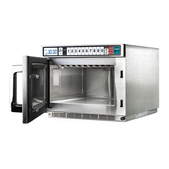
Page 5: Product Specifications
Cooking Uniformity ....Rotary antenna system on eco-design requirements for standby and off mode Weight ......... Approx. 20kg electric power consumption. Sharp do not recommend the product for domestic application and will not accept • As part of a policy of continuous improvement, we reserve any liability for such use. -
Page 6: General Information
• When you order accessories, please mention the two • Operation manual items: part name and model name to your dealer or • Touch guide SHARP authorized service agent. • Caution sheet • The model name is printed on the door of the microwave (SPECIAL INSTRUCTIONS AND WARNINGS) -
Page 7: Test Procedures
R-7500AT TEST PROCEDURES [1] INTERLOCK SWITCH -1 AND/OR -2 TEST 1.Disconnect the power supply cord, and then remove outer case. 2.Open the door full assy and block it open. 3.Wait for 60 seconds to discharge the high voltuge capacitor of the inverter unit. - Page 8 R-7500AT 6.Reinstall the outer case (cabinet). 7. Reconnect the power supply cord after the outer case are installed. 8. Run the oven and check all functions. [3] G: MONITOR SWITCH -1 AND/OR -2 TEST 1.Disconnect the power supply cord, and then remove outer case and rear cabinet.
-
Page 9: Wiring
R-7500AT WIRING ●Power supply cord Power supply cord Brown wire Green/Yellow wire Screw Blue wire Noise filter unit ●Noise fi lter unit and Fuses F10A Blue・Red Noise filter unit (Blue case) Fuse-1 Red・Red White Fuse-2 Red・Red Red・Red (Blue case) - Page 10 R-7500AT ●Latch switches Cabinet side Monitor switch-1 Monitor switch-2 COM: Red (Cabinet side) (Oven side) Oven side Cabinet side COM: Red NC: White Oven side NC: Gray Interlock switch-2 (Oven side) Cabinet side Interlock switch-1 NC: Gray・Black (Cabinet side) Oven side NO: Gray・Blue...
- Page 11 R-7500AT ●Power unit Control harness:Green・Blue CN21 No3: Gray Power unit No1:Green No1:Red No2:Red Bottom plate sub assy Earth wire of power unit: Green ●Relay unit Control harness Connector Control harness Relay unit Connector CND Main harness Oven side:Blue Main harness...
- Page 12 R-7500AT Wiring to Relay and motor harness ● Current transformer Motor harness Wire lead to Relay :Blue Control unit ● Ribbon cable of FPC Control unit Connector CNF of Connector CNG of control harness control harness...
- Page 13 R-7500AT ●Inverter unit CN-A: FA: HV wire assy Red F: HV wire assy Red (with case) harness No.1: Red No.2: White No.3: Blue Printed wiring board Inverter Inverter harness unit Blue Heat sink M: Inverter harness Red Warning: Disconnect power supply before servicing.
- Page 14 R-7500AT ●Wiring to MGT thermistor-1 ①Connect the connector of MGT thermistor-1 to the connector of the control harness. ②Insert the connected connectors into the hole of the rear duct. ③Put the cloth tape on the portion where the connectors are inserted at the rear duct.
- Page 15 R-7500AT Magnetron-1 Rear duct Cloth tape Control harness (Wiring with tape at rear side) ● Blower motor-1 Red・Red White・Gray Blower motor-1...
- Page 16 R-7500AT Blower motor-2 ● Blower motor-2 Gray...
- Page 17 R-7500AT Wiring(Antenna motor) Antenna motor-2 ● Antenna motor -2 Cavity assy top plate Red・Red Blue・White Antenna motor-1 ● Antenna motor -1 Motor harness:Red Motor harness:Gray...
- Page 18 R-7500AT ● Exhaust thermistor Exhaust duct A Control harness Main harness Exhaust thermistor Inverter harness PWM harness LED Light Cavity assy (Left side) Exhaust temp. fuse 120℃ ● Exhaust duct A Exhaust temp. fuse 120℃ Gray Main harness Gray Gray...
- Page 19 R-7500AT ●Positions of wire holders ・At the following eight(8) positions, hold the wire leads with wire holders so that the wire leads do not touch to any sharp edges. Blower motor-2 Wire holder Exhaust duct A Wire holder Cavity assy...
- Page 20 R-7500AT Wire holder Exhaust duct A Antenna motor-2 Cavity assy (Top side) Wire holder Wire holder Wire holder Separate angle Wire holder Screw HV wire assy Inverter cover R...
- Page 21 R-7500AT Wire holder Blower motor-1 ●Wiring of earth wires of inverter unit-2 ①Secure the two(2)earth wires wires of the inverter unit-2 to the inverter support AG L and the bottom plate sub assy with the two(2) screws. ②After the earth wire is fixed to the bottom plate sub assy with the one(1) srew,hold the earth wire to the inverter supp AG L with the cloth tape, as shown in the picture.
- Page 22 R-7500AT ●Wiring of earth wires of inverter unit-1 ①Secure the two(2)earth wires of the inverter unit-1 to the thermal cover and the waveguide of the cavity assy with the two(2)screws. ②After the earth wire is fixed to the waveguide of the cavity assy,hold the earth wire to the thermal cover with the cloth tape,as shown in the picture.
-
Page 23: Ciruits
R-7500AT CIRUITS... - Page 24 R-7500AT 〔2〕 POWER UNIT CIRCUIT...
- Page 25 R-7500AT [ 3 ] INVERTER UNIT CIRCUIT...
- Page 26 R-7500AT CTRL...
-
Page 27: Troubleshooting
R-7500AT TROUBLESHOOTING EXHAUST TEMP.FUSE 120℃ CHECK OF LIGHT SETTING BLOCKED VENTILATION OPENINGS OPENED WIRE HARNESS MISADJUSTMENT OF SWITCHES POWER SUPPLY CORD LED LIGHT EXHAUST THERMISTOR MGT THERMISTOR-2 MGT THERMISTOR-1 FUSE-2 F10A FUSE-1 F10A NOISE FILTER UNIT (FUSE 20A) BLOWER MOTOR-2... - Page 28 R-7500AT Information for the troubleshooting The systems to drive the magnetron-1 and the magnetron-2 are separated into the two (2) systems. So, please refer to the following table. 1. Parts for the circuit to drive the magnetron-1 2. Parts for the circuit to drive the magnetron-2 ・Magnetro-1...
- Page 29 R-7500AT...
- Page 30 R-7500AT...
- Page 31 R-7500AT [3] Check in the event of no microwave cooking Check of high voltage sections is very dangerous. Therefore, disconnect the main power and wait for at least one (1) minute before starting the check. Remove the outer case cabinet.
- Page 32 R-7500AT [4] Check procedure for normal operation (opeartion of display and parts) In case of the setting at the time of factory shipments Order Procedures Display Opeartion Close the door and then ・The display does not connect the power supply show anything.
-
Page 33: Test Mode And Input Current Adjustment
R-7500AT TEST MODE AND INPUT CURRENT ADJUSTMENT... - Page 34 R-7500AT...
- Page 35 R-7500AT [2] ADJUSTMENT PROCEDURE OF INPUT CURRENT After at least one of the inverter units, control unit and magnetrons is exchanged, adjustment of the input current is necessary to make the rating microwave output power to 1800W by following procedure.
-
Page 36: Service Counters
R-7500AT SERVICE COUNTERS SERVICE COUNTERS [1] Clear and input of service counters 1. When the following parts are exchanged, clear (make into zero) the count (using time or using count). About the operation method, refer to each reset method of the service counter table ・Magnetron-1... - Page 37 R-7500AT...
- Page 38 R-7500AT...
-
Page 39: Component Replacement And Adjustment Procedure
4. If the outer case (cabinet) is not fitted. WARNING FOR WIRING To prevent an electric shock, take the following precau- tions. 3) Sharp edge: 1. Before wiring, Bottom plate, Oven cavity, Waveguide flange Chassis 1) Disconnect the power supply cord.
Need help?
Do you have a question about the R-7500AT and is the answer not in the manual?
Questions and answers