Advertisement
Quick Links
Advertisement

Subscribe to Our Youtube Channel
Related Manuals for CR Remeha QUINTA ACE Series


Summary of Contents for CR Remeha QUINTA ACE Series
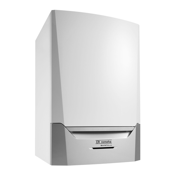
- Page 1 QUINTA ACE RANGE...
- Page 2 WHAT’S INSIDE 03 WELCOME TO REMEHA 52 FLUECADE SYSTEM 03 QUINTA ACE RANGE 53 FLUECADE KITS 04 BOILER CONSTRUCTION 57 FLUECADE COMPONENTS 06 OPERATING PRINCIPLE 61 CASCADE OPTIONS 07 TECHNICAL INFORMATION 63 INSTALLATION AND CONFIGURATION 09 ENGINEERING SPECIFICATION 68 BESPOKE RIG SYSTEMS 11 DIMENSIONS AND CONNECTIONS 71 TECHNICAL SUPPORT...
- Page 3 QUINTA ACE RANGE WELCOME TO REMEHA, THE EXPERT CHOICE WE LEAD THE WAY IN INNOVATION, RELIABILITY AND EFFICIENCY FOR ADVANCED COMMERCIAL HEATING SOLUTIONS. We’re completely focused on commercial heating solutions and are at the forefront of condensing gas boiler technology –...
- Page 4 QUINTA ACE 30 - 115 BOILER CONSTRUCTION Casing/air box Non-return valve Automatic air vent Heat exchanger (CH) Combined gas valve unit Hydraulic pressure sensor Flue gas measuring point Return sensor Interior light Air intake silencer Supply line Flow sensor Instrument box Flue gas discharge pipe Ionisation/ignition electrode Siphon...
- Page 5 Contact us for 4 4 . . 2 2 . . 1 1 2 2 C C a a s s c c a a d d e e BOILER CONSTRUCTION The boiler is ideally s standard solutions av I I m m p p o o r r t t a a n n t t Contact us for QUINTA ACE 135 AND 160 BOILER...
- Page 6 QUINTA ACE RANGE OPERATING PRINCIPLE The products of combustion in the form of hot flue gases are forced through the heat exchanger, transferring their heat to the system water. The flue gas temperature is reduced to approximately 5°C above the temperature of the system return water, then discharged vertically via the condensate collector, through the 80/125mm (Quinta Ace 30/45) or 100/150mm (Quinta Ace 55/65/90/115, 135 and 160) combined flue/air connection to atmosphere.
- Page 7 OPERATING PRINCIPLE AND TECHNICAL INFORMATION QUINTA ACE TECHNICAL INFORMATION QUINTA QUINTA QUINTA QUINTA QUINTA QUINTA QUINTA QUINTA ACE 30 ACE 45 ACE 55 ACE 65 ACE 90 ACE 115 ACE 135 ACE 160 PERFORMANCE Nominal heat output central heating 8.0-29.8 8.0-40.8 11.1-55.3 12.0-61.5...
- Page 8 QUINTA ACE TECHNICAL INFORMATION QUINTA QUINTA QUINTA QUINTA QUINTA QUINTA QUINTA QUINTA ACE 30 ACE 45 ACE 55 ACE 65 ACE 90 ACE 115 ACE 135 ACE 160 HYDRAULICS Water content litres 17.0 17.0 Resistance @ 15°C ∆T mbar Hydraulic resistance @ 20°C ∆T mbar Nominal flow rate @ 15°C ∆T l/s 0.48 0.65...
- Page 9 TECHNICAL INFORMATION AND ENGINEERING SPECIFICATION SUGGESTED ENGINEERING SPECIFICATION QUINTA ACE CONSTRUCTION CONTROLS The boiler will be a wall-hung type condensing boiler which The boiler will include an “e-Smart” control platform offering may also be installed free-standing on a suitable frame. improved connectivity using the integral MK3 controller.
- Page 10 QUINTA ACE 135 AND 160 CONSTRUCTION CONTROLS The boiler will be a wall-hung type condensing boiler The boiler will include an “e-Smart” control platform offering which may also be installed free-standing on a suitable frame. improved connectivity using the integral MK3 controller. The single piece, cast aluminium heat exchanger and other The controls package will allow the actual and set values to major components are contained within a sealed air box.
- Page 11 ENGINEERING SPECIFICATION DIMENSIONS AND CONNECTIONS QUINTA ACE DIMENSIONS AND CONNECTIONS The complete range of Quinta Ace 30, 45, 55, 65, 90 and 115 boilers has a compact design of h750 x w500 x d500mm. Connection of the combustion gas exhaust pipe; Ø...
- Page 12 QUINTA ACE 135 AND 160 DIMENSIONS AND CONNECTIONS Flue gas outlet connection; Ø 100mm Air supply connection; Ø 150mm Siphon connection 32mm Flow connection; 1¼” Male thread (32mm) Return connection; 1¼” Male thread (32mm) Gas connection; 1” Male thread (28mm)
- Page 13 TYPICAL INSTALLATIONS The schematics presented within this document are generic and therefore are not representative of a design for a specific site application. It is the responsibility of the specifier and the installer to ensure that all system components are appropriately sized for the specific QUINTA ACE TYPICAL INSTALLATION...
- Page 14 QUINTA ACE TYPICAL INSTALLATION Single Quinta Ace 30, 45, 55, 65, 90 and 115 boilers, heating and domestic hot water, using a simple ‘S’ plan. Note: Control PCBs are shown diagrammatically. Some earths and neutrals are omitted for clarity.
- Page 15 TYPICAL INSTALLATION QUINTA ACE TYPICAL INSTALLATION Single Quinta Ace 30, 45, 55, 65, 90 and 115 boilers, heating only with low loss header. Time/temp control 230v supply Pump SH1 Condensate Pump PM1 Flow Return 1 3 2 Main control PCB PCB - SCU - S02 PCB - SCU - X01 PCB - IF 01 PUMP...
- Page 16 QUINTA ACE TYPICAL INSTALLATION Single Quinta Ace boiler, heating with priority hot water using a low loss header. 3-way valve DHW priority Quinta Ace 30/45/55/65 only. Note: When using the Remeha supplied low loss header and pump kit and the DHW diverting valve or primary pump kit, the calorifier must be sited within 3m of the boiler.
- Page 17 TYPICAL INSTALLATION QUINTA ACE TYPICAL INSTALLATION Single Quinta Ace boiler, heating with priority hot water using a low loss header. Pumped option, DHW priority can be used on all Quinta Ace 30, 45, 55, 65, 90 and 115 (see page 21). Note: When using the Remeha supplied low loss header and pump kit and the DHW diverting valve or primary pump kit, the calorifier must be sited within 3m of the boiler.
- Page 18 QUINTA ACE TYPICAL INSTALLATION Single Quinta Ace 30, 45, 55, 65, 90 and 115 boilers, heating only, room compensation using iSense controls. Normal position for the iSense controller mounted in reference room within the building (room compensation) 100m Max 230v supply Pump PM1 Condensate Flow...
- Page 19 TYPICAL INSTALLATION QUINTA ACE TYPICAL INSTALLATION Single Quinta Ace 30, 45, 55, 65, 90 and 115 boilers, heating only, weather compensation using the iSense controls. Normal position for the controller mounted in reference room within the building 100m Max iSense can be fitted in the boiler if used for weather compensation only 100m Max 230v supply...
- Page 20 QUINTA ACE TYPICAL INSTALLATION Single Quinta Ace boiler, heating and hot water priority. Heating room or outside weather compensated with iSense controls. 3-way valve hot water priority Quinta Ace 30/45/55/65 only. Note: When using the Remeha supplied low loss header and pump kit and the DHW diverting valve or primary pump kit, the calorifier must be sited within 3m of the boiler.
- Page 21 TYPICAL INSTALLATION QUINTA ACE TYPICAL INSTALLATION Single Quinta Ace boiler, heating and hot water priority. Heating room or outside weather compensation with iSense controls. Pump option hot water priority can be used on all Quinta Ace 30, 45, 55, 65, 90 and 115. Note: When using the Remeha supplied low loss header and pump kit and the DHW diverting valve or primary pump kit, the calorifier must be sited within 3m of the boiler.
- Page 22 QUINTA ACE TYPICAL INSTALLATION Multiple Quinta Ace 30, 45, 55, 65, 90 or 115, heating only, outside weather or room compensation with the Celcia MC4 and iSense controls with a low loss header (optimising/weather compensated). Normal position for the controller mounted in reference room within the building 100m max...
- Page 23 TYPICAL INSTALLATION QUINTA ACE 135 AND 160 TYPICAL INSTALLATION Suggested hydraulic circuit diagram. Hot water cylinder Note: This information is indicative.
- Page 24 ELECTRICAL INSTALLATION AND CONTROLS QUINTA ACE 30, 45, 55, 65, 90 AND 115 GENERAL CONNECTING A THIRD PARTY CONTROL UNIT TO A STANDARD BOARD The Quinta Ace 30, 45, 55, 65, 90 and 115 is supplied as standard with electronic control and flame ionisation safety controls, with a specially designed microprocessor at the PCB (CU-GH08) heart of the control system.
- Page 25 ELECTRICAL INSTALLATION AND BOILER CONTROLS BOILER CONTROLS ANALOGUE OUTPUT – CAPACITY CONTROL (%) The Quinta Ace range can be controlled using a number of methods – other examples are given below. Scheduling using The 0-10V signal controls the boiler output between 0% and the integral Mk3 controller in conjunction with the recommended 100% of its total capacity (kW).
- Page 26 PRIORITY DHW CONTROL FROST PROTECTION Install the boiler in a frost-free room. The built-in frost protection TEMPERATURE CONTROL system is activated as follows: below 7°C – system pump is With a Remeha temperature sensor or with a standard (volt free) switched on if connected to the boiler.
- Page 27 QUINTA ACE CONTROLS AND SPECIFICATIONS QUINTA ACE 135 AND 160 6 Installation 6 6 . . 6 6 . . 3 3 SPECIFICATIONS ASSEMBLY OF THE CONTROL PANEL Fig.24 Control panel The Qu control X X 0 0 2 2 1 1 m The boiler has a three-wire mains lead (lead length 1.5m) and is The Human Machine Interface (HMI) and the connection box need suitable for a 230VAC/50Hz power supply with a phase/neutral/...
- Page 28 ELECTRICAL INSTALLATION AND CONTROLS QUINTA ACE 135 AND 160 GENERAL CONNECTING A THIRD PARTY CONTROL UNIT TO A STANDARD The Quinta Ace 135 and 160 is supplied as standard with electronic control and flame ionisation safety controls, BOARD CU-GH-06 with a specially designed microprocessor at the heart of the control system.
- Page 29 ELECTRICAL INSTALLATION AND BOILER CONTROLS BOILER CONTROLS The Quinta Ace range can be controlled using a number of INPUT methods – other examples are given below. Scheduling using JUMPER 2 TEMPERATURE A DESCRIPTION SIGNAL (V) the integral Mk3 controller in conjunction with the recommended Outside / Room sensor when connected to the CB-01 control 0-1.5 0-15...
-
Page 30: Flue Options
FLUE OPTIONS The Quinta Ace range of condensing boilers has fan assisted flues. They are supplied as standard with a concentric flue outlet/air inlet connection which is used for room-sealed operation or for open-flue (room ventilated) applications. An optional twin pipe fitting is available for the room-sealed CLV system. - Page 31 FLUE OPTIONS QUINTA ACE RANGE FLUE OUTLET/AIR INLET DETAILS The Quinta Ace range of boilers are supplied as standard with a 2. Conventional/open-flue operation using single skin flue concentric flue outlet/air inlet connection which can be used for: system connected to the inner concentric connection with the air supply taken from the boiler house via the outer 1.
- Page 32 QUINTA ACE 30 AND 45 ROOM-SEALED, 80/125MM HORIZONTAL CONCENTRIC FLUE KIT OPTION QP01 For use when the boiler/s are mounted on and flued through a rear outside wall, and for a typical single-boiler installation. It can also be used for multiple boilers but each must have its own flue system and terminals positioned at a minimum of 530mm centres and never installed immediately above another.
- Page 33 FLUE OPTIONS QUINTA ACE 30 AND 45 ROOM-SEALED, 80/125MM VERTICAL QP30/45 - 495mm CONCENTRIC FLUE KIT OPTION QP03 For use when the flue is discharged vertically through the roof, and for a typical single-boiler installation. It can also be used for multiple boilers, but each must have its own flue system and terminals separated by a minimum of 300mm if it is at the same height.
- Page 34 QUINTA ACE 30 AND 45 80/125MM ROOM-SEALED CALCULATED DATA TO DETERMINE MAXIMUM FLUE RUNS Calculation data based on flue products supplied by Remeha. ROOM-SEALED CALCULATION DATA QUINTA ACE 30 – 80/125MM QUINTA ACE 45 – 80/125MM Maximum overall flue run Metres Reduction length for each 45°...
- Page 35 FLUE OPTIONS QUINTA ACE 30 AND 45 ROOM-SEALED, 100MM TWO ZONE CLV FLUE KIT OPTION QP04 Connection in areas of different pressure (C53). Combustion air supply and combustion gas discharge are possible in various pressure zones, semi-CLV system, with the exception of coastal areas.
- Page 36 QUINTA ACE 30 AND 45 100MM CONVENTIONAL OR OPEN-FLUE SYSTEMS Typical single-boiler installation. Ensure that the overall route does not exceed the maximum values in the table on page 40. Flue outlet CONVENTIONAL OR OPEN FLUE SYSTEMS 100mm aluminium single wall flue system Refer to table on page 35...
- Page 37 FLUE OPTIONS QUINTA ACE 30 AND 45 100MM CONVENTIONAL OR OPEN-FLUE SYSTEMS The components listed below are only suitable for internal use as illustrated on pages 33 and 34. As the boiler is fan assisted it makes no difference if the run is horizontal or vertical but the flue should terminate vertically. Cut down to suit diameter of flue in use and seal with silicone supplied OPEN-FLUE DATA...
- Page 38 QUINTA ACE 30 AND 45 PLUME KITS 80/125MM FLUE KIT OPTION QP05 Plume kit termination positions must not be used to circumvent current standards and regulations, the point of exit determines the flue outlet position. The 80mm plastic discharge components can then be utilised to position the flue gases/plume to a suitable discharge point in line with current regulations.
- Page 39 PLUME KITS 80/125MM PLUME MANAGEMENT COMPONENTS PART DETAIL Note: The components listed below must only be used as part of the Plume Management Kit. PMK-horizontal Terminal – not supplied as a separate component MG410082343 PMK – 90° bend (80mm) MG410082344 PMK –...
- Page 40 QUINTA ACE 30 AND 45 – MULTI-BOILER INSTALLATION ON A COMBINED HEADER It is recommended you consult a flue specialist for the design, manufacture and installation of the flue system. For conventional or open-flue systems, on a typical multi-boiler installation with the flue combined into a single header and riser. INSTALLATION ON A COMBINED HEADER...
- Page 41 FLUE OPTIONS QUINTA ACE 30 AND 45 MULTI OR SINGLE-BOILER INSTALLATION ON A FLUE DILUTION SYSTEM Remeha is unable to offer a flue dilution system and recommends the installer contacts a flue specialist to design and manufacture the system in accordance with the requirements of the British Standards. A typical installation for a flue dilution system showing the flue break necessary for all pre-mix boilers to prevent the dilution fan affecting the gas/air ratio control system in the boiler.
- Page 42 QUINTA ACE 55, 65, 90, 115, 135 AND 160 ROOM-SEALED, 100/150MM HORIZONTAL CONCENTRIC FLUE KIT For use when the boiler/s are mounted on and flued through the outside wall and on a typical single-boiler installation – can also be used for multiple boilers but each must have its own flue system. At a minimum of 530mm centres and never immediately above another.
- Page 43 FLUE OPTIONS QUINTA ACE 55, 65, 90, 115, 135 AND 160 ROOM-SEALED, 100/150MM VERTICAL CONCENTRIC FLUE KIT For use when the flue is discharged vertically through the roof and on a typical single-boiler installation. It can also be used for multiple boilers but each must have its own flue system and be separated by a minimum of 300mm if at the same height.
- Page 44 QUINTA ACE 55, 65, 90, 115, 135 AND 160 100/150MM ROOM-SEALED CALCULATION DATA TO DETERMINE MAX FLUE RUNS Calculation data based on flue products supplied by Remeha. QUINTA QUINTA QUINTA QUINTA QUINTA QUINTA ROOM-SEALED FLUE DATA ACE 55 ACE 65 ACE 90 ACE 115 ACE 135...
- Page 45 FLUE OPTIONS QUINTA ACE 55, 65, 90, 115, 135 AND 160 ROOM-SEALED TWO ZONE CLV FLUE KIT The Quinta Ace boiler can be installed in areas with different pressure zones if connected to a C53 flue system. An integral non return valve is fitted as standard. Combustion air supply and combustion gas discharge are possible in various pressure zones, semi-CLV systems.
- Page 46 QUINTA ACE 55, 65, 90, 115, 135 AND 160 CONVENTIONAL OR OPEN-FLUE SYSTEMS Typical single-boiler installation. It can also be used for multiple boilers with each boiler having its own flue system. CONVENTIONAL OR OPEN FLUE SYSTEMS QUINTA QUINTA QUINTA QUINTA QUINTA QUINTA...
- Page 47 FLUE OPTIONS 100MM SINGLE WALL ALUMINIUM FLUE COMPONENTS ALUMINIUM FLUE COMPONENTS Cut down to suit diameter of flue in use and seal with silicone supplied 101 i/d 600mm x 500mm Detail of standard weathering plate for 100mm to 150mm flue (Part No. VE001) 101 i/d Flue terminal c/w bird guard 101 i/d...
- Page 48 QUINTA ACE 55, 65, 90, 115, 135 AND 160 100/150MM FLUE KIT OPTION QP11 Plume kit termination positions must not be used to circumvent current standards and regulations. The point of exit determines the flue outlet position. The 100mm aluminium discharge components can then be used to position the flue gases/plumes to a suitable discharge point, again in line with current regulations.
- Page 49 FLUE OPTIONS PLUME KITS 100/150MM PLUME MANAGEMENT COMPONENTS PART DETAIL COMPONENTS PART DETAIL MG410081752 PMK – horizontal terminal PMK – 45° bend (100mm) Not supplied as a separate component MG410081755 Bird mesh 100mm Dn 100 MG410081753 Dn 100 Dn 100 PMK –...
- Page 50 QUINTA ACE 55, 65, 90, 115, 135 AND 160 MULTI OR SINGLE-BOILER INSTALLATION ON A FLUE DILUTION SYSTEM Remeha is unable to offer a flue dilution system and recommends that the installer contacts a flue specialist to design and manufacture the system in accordance with the requirements of the British Standards. Typical multi-boiler installation for a flue dilution system showing the flue break necessary for all pre-mix boilers to prevent the dilution fan affecting the gas/air ratio control system in the boiler.
- Page 51 PLUME KITS QUINTA ACE 55, 65, 90 AND 115 – MULTI-BOILER INSTALLATION ON A COMBINED HEADER It is recommended you consult a flue specialist for the design, manufacture and installation of the flue system. For conventional or open-flue systems in a typical multi-boiler installation with the flue combined into a single header and riser. MULTI BOILER INSTALLATION...
- Page 52 FLUECADE SYSTEM The Fluecade system can only be used on the Quinta Ace 30, 45, 55, 65, 90 and 115 boilers from two boilers up to a maximum of six in-line and back-to-back. The flue is designed for internal use in a plant room and not for external use. The system comes complete with all associated components.
- Page 53 FLUECADE KITS THIS BASIC PP 200MM FLUECADE HEADER KIT IS SUITABLE FOR THE CONNECTION OF TWO QUINTA ACE BOILERS – IN AN IN-LINE CONFIGURATION Please refer to table on page 58 to determine the maximum length and diameter of the fluecade system for the Quinta Ace range of boilers.
- Page 54 THIS BASIC PP 200MM FLUECADE EXTENSION KIT IS SUITABLE FOR THE CONNECTION OF AN EXTRA QUINTA ACE BOILER – IN AN IN-LINE CONFIGURATION Please refer to table on page 58 to determine the maximum length and diameter of the fluecade system for the Quinta Ace range of boilers.
-
Page 55: Back-To-Back Configuration
FLUECADE KITS THIS BASIC PP 200MM FLUECADE HEADER KIT IS SUITABLE FOR TWO QUINTA ACE BOILERS – IN A BACK-TO-BACK CONFIGURATION Please refer to table on page 58 to determine the maximum length and diameter of the fluecade system for the Quinta Ace range of boilers. BACK-TO-BACK CONFIGURATION Kit parts –... - Page 56 THIS BASIC PP 200MM FLUECADE EXTENSION KIT IS SUITABLE FOR TWO QUINTA ACE BOILERS – IN A BACK-TO-BACK CONFIGURATION Please refer to table on page 58 to determine the maximum length and diameter of the fluecade system for the Quinta Ace range of boilers. BACK-TO-BACK CONFIGURATION Kit parts –...
- Page 57 FLUECADE KITS FLUECADE COMPONENTS FLUECADE COMPONENTS Flue header 200mm Part No. MG410076748 Flue header 200mm Part No. MG410081949 Quinta Pro 30/45 80mm x 125mm Air intake grill (parallel) 80mm Part No. MG410076039 boiler connection Part No. MG410076724 Air intake grill (parallel) 100mm Part No. MG410079314 Air intake grill (concentric) 80/125mm Part No.
- Page 58 FLUECADE COMPONENTS Wall bracket 200mm Part No. MG410087198 100mm 45° elbow Part No. MG410085142 90° elbow 100mm Seal HR – EPDM 200mm Part No. MG410027360 Part No. MG410085141 Seal HR – EPDM 150mm Part No. MG410027358 Seal HR – EPDM 100mm Part No. MG410027356 Straight flue 100mm x 500mm Condense adaptor Part No.
- Page 59 FLUECADE COMPONENTS FLUECADE 200mm PP roof terminal Part No. MG410070439 200mm flat roof flashing Part No. MG410079612 200mm chimney cap Part No. MG410087398 Straight flue 200mm x 2000mm Part No. MG410070404 Straight flue 200mm x 1000mm Part No. MG410070402 Ventilation grate 250mm x 300mm (175cm Cover plate 300mm x 300mm with sleeve Part No.
- Page 60 DATA TO DETERMINE THE MAXIMUM LENGTH AND DIAMETER OF THE FLUECADE SYSTEM FOR THE QUINTA ACE RANGE OF BOILERS BOILER UNIT QACE30 QACE45 QACE55 QACE65 QACE90 QACE115 Heat input net kW 30.0 41.2 56.5 107.9 Max back pressure at full load Max back pressure at ignition HEAT INPUT kW CONFIGURATION...
- Page 61 FLUECADE DATA AND CASCADE OPTIONS CASCADE OPTIONS Spreading the total required heat output over several boilers Quinta Ace 30, 45, 55, 65, 90 and 115 boilers are particularly in cascade configuration offers several advantages: suitable for use in cascade systems due to their small footprint and width of only 50cm which allows an exceptionally compact greater reliability •...
- Page 62 QUINTA ACE INSTALLATION DRAWINGS FOR WALL-MOUNTED CASCADE SYSTEMS The cascade systems can be divided into three main groups: two to eight boilers in a linear configuration, wall-mounted • two to eight boilers in a linear configuration, mounted on a free-standing frame •...
- Page 63 INSTALLATION DRAWINGS AND LINEAR CONFIGURATION QUINTA ACE LINEAR CONFIGURATION, MOUNTED ON A FREE-STANDING FRAME – TWO TO EIGHT BOILERS QUINTA ACE 30, 45, 55, 65, 90 AND 115 Free-standing frame configuration. 3230 3150 T003419-A Low loss header System flow; connection DN 100 DN 65 = 633mm Gas supply connection or 125/DIN 2631 (8 holes)
- Page 64 QUINTA ACE BACK-TO-BACK MOUNTED OR FREE-STANDING FRAME CONFIGURATION (RG) – THREE TO TEN BOILERS QUINTA ACE 30, 45, 55, 65, 90 AND 115 Back-to-back mounted on a free-standing frame configuration. 1055 2620 2650 System flow; connection DN 100 Distance to system return Gas supply connection or 125/DIN 2631 (8 holes) connection = 200mm...
- Page 65 INSTALLATION DRAWINGS AND LINEAR CONFIGURATION STRUCTURE OF QUINTA ACE 135 AND 160 CASCADE SYSTEMS Complete cascade options are available for the Quinta Ace 135 and 160 with both insulated and non-insulated versions. QUINTA ACE 135 AND 160 Two to eight Quinta Ace 135 and 160 boilers in a linear configuration, mounted on a free-standing frame.
- Page 66 STRUCTURE OF QUINTA ACE 135 AND 160 CASCADE SYSTEMS Complete cascade options are available for the Quinta Ace 135 and 160 with both insulated and non-insulated versions. QUINTA ACE 135 AND 160 Three to eight Quinta Ace 135 and 160 boilers in a back-to-back configuration, mounted on a free-standing frame.
- Page 67 INSTALLATION AND CONFIGURATION MULTIPLE OUTPUT QUINTA BOILER CASCADES Remeha also offers options for multiple output configurations combining Quinta Ace 30 to 115 with Quinta Ace 135 and 160 boilers. QUINTA BOILER CASCADES Please contact your local Sales Manager for further information. Contact details are available via the website remeha.co.uk 1603.5mm i n t...
- Page 68 BESPOKE RIG SYSTEMS We provide bespoke rig system service to support consultants in overcoming plant room limitations and tight deadlines. These rigs are designed and manufactured to meet the exact requirements of each individual project so that they can be installed in a fraction of the time.
- Page 69 BESPOKE RIG SYSTEMS BESPOKE RIG SYSTEMS WITH PHE View without insulation View without insulation 3x Quinta Ace 160 3x Quinta Ace 160 DN100 PN16 EN1092-1 DN100 PN16 EN1092-1 View without insulation system flow/return system flow/return 3x Quinta Ace 160 PHE - 480 kW PHE - 480 kW DN100 PN16 EN1092-1 system flow/return...
-
Page 71: Technical Support
TECHNICAL SUPPORT AND DECLARATION OF COMPLIANCE TECHNICAL SUPPORT From brochures to CAD drawings and BIM files, you can access all the information you need at remeha.co.uk Or call our sales or technical departments on 0345 070 1055. We’re always happy to help. We can provide you with: Brochures CAD files... - Page 72 Innovation House 3 Oaklands Business Centre Oaklands Park Wokingham RG41 2FD T 0345 070 1055 E info@baxiheating.co.uk W remeha.co.uk Registered address: Baxi Heating UK Ltd Brooks House Coventry Road Warwick CV34 4LL Quinta Ace Specification Guide February 2021...
Need help?
Do you have a question about the QUINTA ACE Series and is the answer not in the manual?
Questions and answers