Table of Contents
Advertisement
Quick Links
1 First Steps
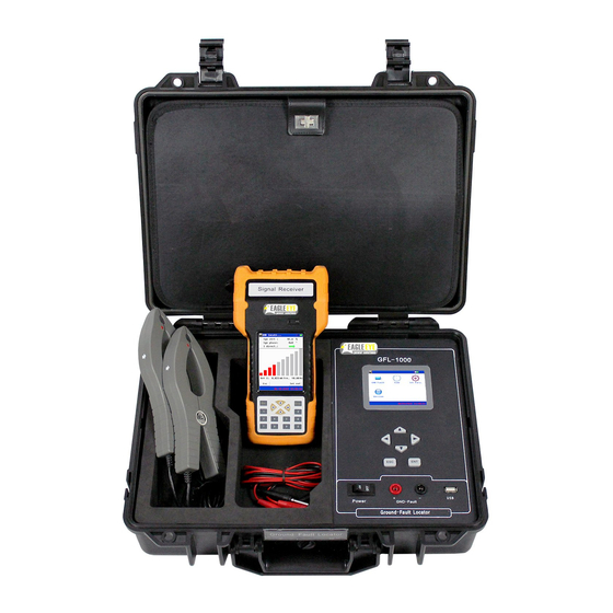
Plug in the test leads to the sockets on the front of the Signal Generator. Connect
the red lead to the red socket marked (+) and the black lead to the black socket
marked (-). Ensure these are correctly connected.
Plug in the Current clamps to the connection at the top of Signal Receiver.
Determine which bus (i.e. positive or negative) has a fault by connecting a
multimeter, set to measure DC volts, between ground and each bus in turn.
Generally the fault will be on the bus which gives the lowest voltage reading.
Now connect the signal generator to the faulty bus.
o If the positive bus appears faulty, connect the positive (red lead and
connector) to that bus, and the negative (black lead and connector) to
ground.
o If the negative bus is faulty, connect the negative lead to it, and connect
the positive lead to ground.
Switch the units on at the power switch.
1.1 Setting up the Signal Generator
On the main screen select GND-Fault using the arrow keys until it is highlighted;
then press ENT. The next screen will allow the output signal to be adjusted.
Set the output voltage and current limit by highlighting the appropriate value
using the left and right arrow keys, adjusting the value using the up down arrow
keys. Select the output voltage closest to the voltage of the bus under test
Select Next to continue. The signal generator voltage and current waveforms will
appear, together with calculated values of fault current, resistance and leakage
capacitance.
Press Cont. In the next screen adjust the current and voltage if necessary.
Select Next. The screen should display current and voltage waveforms as
before.
www.eepowersolutions.com | Tel: 1-877-805-3377 | Fax: 1-414-962-3660 | info@eepowersolutions.com | V1.1
GFL-Series Quickstart Guide
1
Quickstart Guide V1.1
Advertisement
Table of Contents

Related Manuals for Eagle Eye GFL Series


Summary of Contents for Eagle Eye GFL Series
- Page 1 Quickstart Guide V1.1 GFL-Series Quickstart Guide 1 First Steps Plug in the test leads to the sockets on the front of the Signal Generator. Connect the red lead to the red socket marked (+) and the black lead to the black socket marked (-).
- Page 2 Quickstart Guide V1.1 GFL – 1000 Getting Started Guide The signal generator is now producing a continuous output voltage and current which is displayed on the screen. 1.2 Setting up the Signal Receiver Select GND-Fault from the initial signal receiver screen. The green light above the screen should flash every second or so.
- Page 3 Quickstart Guide V1.1 GFL – 1000 Getting Started Guide 2 Tracing the Fault The fault is traced by following the current from the signal generator through the wiring system until the faulty branch is located. Figure 2-1 shows how a fault can be traced by moving the clamp by following the green arrow, until the faulty branch is isolated.
- Page 4 For detailed instructions on setting up, using the GFL – 1000 to detect other types of faults, and for full information concerning features such as the Spectrum Analyzer and Oscilloscope, please refer to the full handbook. For help and support, please contact Eagle Eye: Call: 1-414-962-EEPS (3377) Toll Free: 1-877-805-EEPS (3377) info@eepowersolutions.com...
Need help?
Do you have a question about the GFL Series and is the answer not in the manual?
Questions and answers