
Related Manuals for Eagle Eye BMS-icom


Summary of Contents for Eagle Eye BMS-icom
- Page 1 Eagle Eye Power Solutions, LLC BMS-icom Battery Monitoring System for 48V Installation Manual 062918 www.eepowersolutions.com | Tel: 1-877-805-3377 | info@eepowersolutions.com...
-
Page 2: Table Of Contents
BMS-icom Installation Manual Contents 1. Introduction ..........................2 2. Safety Overview ........................2 3. Package Contents ........................3 4. Required Tools ........................5 5. Installation Instructions ......................6 Step 1: Mount BMS Unit ......................6 Step 2: Clamp Setup ......................... 6 Step 3: Sensing Cable Connection ................... -
Page 3: Introduction
BMS-icom Installation Manual 1. Introduction Thank you for choosing Eagle Eye Power Solution’s BMS icom. The BMS icom is designed to monitor and analyze the aging status of up to (24) cells (4) jars by measuring and recording: § STRING: Voltage & Current §... -
Page 4: Package Contents
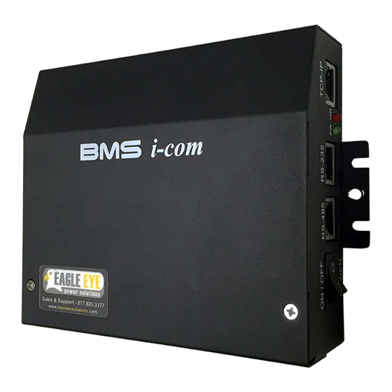
BMS-icom Installation Manual 3. Package Contents The following parts come standard in the BMS icom package. Each package will come with either O-Type clamps or C-Type clamps. Part Name & Purpose Picture BMS icom Main body of the unit. C-Type Clamp Clamp used for connection to bus bars. - Page 5 BMS-icom Installation Manual Power Cable (3-Pin) Positive(+) red Negative(-) blue Temperature Cable (8-pin) & Sensors Measures temperature of battery posts Voltage Sensing Cable (6-pin) Measures voltage (Vs) Current Sensing Cable (4-pin) Measures current (Is) Temperature Sensors...
-
Page 6: Required Tools
BMS-icom Installation Manual 4. Required Tools Tool Name & Purpose Picture Multimeter Verification of connection voltage & resistance #1 Phillips Screwdriver BMS clamp installation (2-3 mm) Flathead Screwdriver Termination of sensing cable to clamps Wire Stripper (16, 22 AWG req.) -
Page 7: Installation Instructions
BMS-icom Installation Manual 5. Installation Instructions The following steps will provide the correct workflow for installing the BMS icom battery monitoring system and all of its components to a battery string. Step 1: Mount BMS Unit Parts: BMS MPU, mounting hardware (not included) - Page 8 BMS-icom Installation Manual (1) Prepare for Connection 1. Organize clamps based on type and verify that all clamps are present 2. Ensure all intercell connections are secure and torqued to spec (2) Connection of Clamps (C-Type) 1. Place the clamp in the center of the bus-bar and tighten down using the provided screws 2.
-
Page 9: Step 3: Sensing Cable Connection
BMS-icom Installation Manual Step 3: Sensing Cable Connection Parts: Clamps, clamp covers, voltage sensing cables, current sensing cables Phillips screwdriver, 2-3mm flathead, duct, duct tape, cable ties/zip ties, wire cutter, Tools: wire stripper (22 AWG) (1) Connection Order There are two sensing cables, voltage and current, which connect to the clamps. Each cable has a number of sensing leads which are color coded to help with installation. -
Page 10: Step 4: Control Power Cable
BMS-icom Installation Manual Step 4: Control Power Cable Parts: Control Power Cable, C-Clamp (if applicable) Tools: Phillips driver, cable/zip ties The BMS icom is powered by the batteries which it is connected to. The control power cables are also used to monitor string voltage. -
Page 11: Step 5: Temperature Cable
BMS-icom Installation Manual Step 5: Temperature Cable Parts: Temperature sensors, TS cable Tools: Tape, silicone Each BMS unit comes standard with (2) temperature sensing leads. The lead is used to measure temperature near the battery post. (1) Place Temperature Leads 1. -
Page 12: Step 7: Verify Connections
BMS-icom Installation Manual Step 7: Verify Connections Parts: Sensing Cables, Clamps Tools: Multimeter or voltmeter Before plugging cable connectors into the MPU, be sure to check each connection using a multimeter. (1) Check Voltage & Current Sensing Connections 1. With the connector end of the cable in hand, insert the positive lead from the multimeter into the grey port 2. -
Page 13: Step 8: Connect Cables To Mpu
BMS-icom Installation Manual (2) Troubleshooting Incorrect Voltage 1. If voltage is incorrect, connections will need to be checked 2. Set the Multimeter to measure resistance and test the connection between the sensing screw and the sensing cable 3. If the Multimeter displays zero resistance (0.00Ω) then the connection is good. If the... -
Page 14: Communication Setup
BMS-icom Installation Manual 6. Communication Setup The BMS icom can communicate directly to a server PC or over a network for remote monitoring of battery systems. The following steps will provide the correct workflow for connecting the BMS icom to a PC or network. -
Page 15: Step 2: Configure Mpu Ip
BMS-icom Installation Manual Step 2: Configure MPU IP Parts: BMS MPU, Computer Tools: For communication, the BMS MPU needs to be assigned an IP address. Use the provided WIZ100SR configuration utility to establish connection. This configuration tool can be found on the provided USB drive. -
Page 16: Step 3: Configure Centroid Snet
BMS-icom Installation Manual (2) Configure MPU IP Address 1. Launch “WIZ1x0SR_105SR_CFG.exe” 2. Click “Search” to locate the MPU 3. The MPU MAC address will appear under “Board List” 4. Local IP refers to the MPU IP address. To change the IP, enter it in this field 5. -
Page 17: Specifications
BMS-icom Installation Manual 7. Specifications Battery Types: VRLA Battery Capacity Range: Up to 6000 Ah Cell Voltage: 1 – 16 VDC DC Voltage / Current: ±0.5% / ±1% Temperature: ±2% Accuracy: Internal Resistance: ±2% Cell Voltage: ±1% AC Voltage / Current: 0.1 V / 0.1 A DC Voltage / Current: 0.1 V / 0.1 A... -
Page 18: Support
BMS-icom Installation Manual 8. Support For further support or additional questions, please contact Eagle Eye via phone or email.
Need help?
Do you have a question about the BMS-icom and is the answer not in the manual?
Questions and answers