Table of Contents
Advertisement
Advertisement
Table of Contents

Related Manuals for Rugged Radios ABM25


Summary of Contents for Rugged Radios ABM25
- Page 1 COVER COVER...
- Page 2 PLEASE READ STOP Thank you for purchasing a Rugged Radios 2-way radio. This radio was optimized before shipping to you. Please be sure to read this manual before changing any settings. If you have any questions, call the Rugged Radios Tech Department at 888-541-7223.
- Page 3 Notes: ______________________________________________________ ______________________________________________________ ______________________________________________________ ______________________________________________________ ______________________________________________________ ______________________________________________________ ______________________________________________________ ______________________________________________________ ______________________________________________________ ______________________________________________________...
- Page 4 0678...
-
Page 5: Table Of Contents
Contents Users Safety Information ...................1 Package Includes ......................1 Main Features ......................2 Initial Installation ......................3 Mobile Installation .................... 3 DC Power Cable Connection................4 Fixed Station Operation ................... 5 Replacing Fuses ....................7 Antenna Connection ..................8 Accessories Connections...................9 External Speaker ..................... 9 Microphone .................... - Page 6 Switch between VFO and Channel Mode ............. 17 Adjusting Frequency/Channel through Selector Knob ........17 Receiving ....................... 18 Transmitting ....................18 Transmitting Tone-Pulse ................18 Transmitting Optional Signaling ..............18 Channel Edit ....................19 Channel Delete ....................19 Shortcut Operations ....................20 Frequency Scan ....................
- Page 7 High/Mid/Low Power Selection (FUN+8) ............24 DTMF Current Channel Edit (FUN+9/Scan) ..........24 Channel Deleted Quickly (FUN+VFO) ............25 Channel Copied Quickly (FUN+Call) ............. 25 Talk Around (FUN+*) ..................25 Reverse Frequency (FUN+#) ................ 25 Menu ...........................26 1. Signaling ....................26 2.
- Page 8 2 Tone encode ....................41 2 Tone decode ....................41 5 Tone Operation .......................41 5 Tone encode ....................41 Simple Trouble Shooting ..................42 Specifications ......................43 General ......................43 Receiver ......................43 Transmitter..................... 44...
-
Page 9: Users Safety Information
Users Safety Information ● Do not attempt to configure your radio while driving. ● This radio is designed for a 13.8V DC power supply. Do not use a 24V battery to power on the radio. ● Please keep it away from interference devices (Such as TVs, generators, etc.) ●... -
Page 10: Main Features
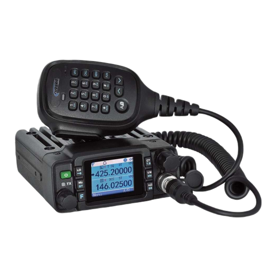
Dirt, Mud & Water... It's all part of the off-road riding and now we've got a radio that will withstand it all! . ABM25 amateur mobile radio is stout and reliable, ready for any adventure. This radio is also equipped with a Rugged Accessory Port allowing you to... -
Page 11: Initial Installation
Initial Installation Mobile Installation To install the radio select a safe and convenient location inside your vehicle that min- imizes danger to your passengers and yourself while the vehicle is in motion. Consider installing the unit at an appropriate position so that knees or legs will not strike it during sudden braking of your vehicle. -
Page 12: Dc Power Cable Connection
■ Determine the appropriate angle of the radio, using the 3 screw hole positions On the side of the mounting bracket. DC Power Cable Connection Note: Locate the power input connector as close to the radio as possible. The vehicle battery must have a nominal rating of 12V. Never connect the radio to a 24V battery. Be sure to use a 12V vehicle battery that has sufficient current capacity. -
Page 13: Fixed Station Operation
3. Reconnect any writing removed from the negative terminal. 4. Connect the DC power cable to the radio’s power supply connector. Press the connectors firmly together until the locking tab clicks. DC power cable Ext. Power jack Fixed Station Operation In order to use this radio for fixed station operation you will need a separate 13.8V DC power supply (not included). - Page 14 Use the supplied DC power cable to connect the radio to a regulated power supply. Do not substitute a cable with smaller gauge wires. 2. Connect the radio’s DC power connector to the connector on the DC power cable. 3. Press the connectors firmly together until the locking tab clicks. Note: Before connecting the DC power to the radio be sure to switch the radio and the DC power supply OFF.
-
Page 15: Replacing Fuses
If the fuse blows, determine the cause then correct the problem. After the problem is resolved replace the fuse. If newly installed fuses continue to blow, disconnect the power cable and contact your Rugged Radios for assistance. Only use fuses of the specified type and rating otherwise the radio could be damaged. -
Page 16: Antenna Connection
50Ω reduces the efficiency of the antenna system and can cause interference to nearby broadcast TV receivers, radio receivers and other electronic equipment. Rugged Radios Models/Option • #DB-RM - Dual Band Mobile Antenna • #WB-1/4W - UHF/VHF Wide Band 1/4 Wave Antenna (140-470mhz) •... -
Page 17: Accessories Connections
Accessories Connections External Speaker If you plan to use an external speaker, choose a speaker with an impedance of 8Ω. The external speaker jack accepts a 3.5mm mono (2-conductor) plug. Optional Speaker: #EX-SPEAKER-MINI Note: External speaker output adopts double port BTL. Please be aware that the speaker can’t connect to the ground otherwise the speaker will fault. -
Page 18: Microphone
Microphone: For voice communications, connect a microphone equipped insert into the modular socket on the side of the main unit and tighten the screw. Attach the supplied microphone hanger in an appropriate location using the screws includes included in the screw set NOTE: If you plan on using a intercom, disconnect the hand microphone. -
Page 19: Getting Acquainted
Getting Acquainted Front Panel Operation... - Page 20 Function POW (Power) Power on/off Adjust volume key Main Dial Change frequency, memory channel and scan direction etc. Function key Short press to switch power output level Lo ( Long press to switch the offset direction Short press to adjust the frequency by 1M step in VFO mode, to adjust the channel number by 10 in channel mode Mz(ST) Long press to adjust the frequency by 10M step...
- Page 21 Multi-Function Key Function Short press to switch the home screen/sub screen Long press to switch the UHF/VHF in the VFO mode Short press to switch the power output level Long press to switch the offset direction Short press to start monitor MONI Long press to turn on/off the channel name Short press to start scan...
-
Page 22: Display
Display Icon Function Memory Channel Number High Power Output / Middle Power Output/ Low Power Output W/M/N Wide Bandwidth/ Middle Bandwidth/ Narrow Bandwidth DT/2T/5T Signaling CTCSS Encode CTCSS Decode DCS Encode and Decode Beep Auto Power-off Frequency Mode Positive Direction of Offset... -
Page 23: Microphone
Icon Function Negative Direction of Offset Home Screen Position Scan Lock the Keypad Rugged 5 Pin Accessory Port Rear Panel Must remain closed to be waterproof. Microphone Port Function Connection for 50Ω antenna DATA PC programming data port EXT SP Terminal for optional external speaker... - Page 24 ICON Function Press the key to transmit Λ Decrease volume or setting value Increase volume or setting value Speak here during transmission Indicate light Indicate light will red during transmission Number Key Input channel number or DTMF dial out etc. Exchange to the home screen and sub screen...
-
Page 25: Basic Operation
Basic Operation Switching the Power On/Off According to the option selected during installation, press the key for 1s to power on radio. Press the key for 2s to power off radio. Adjusting the Volume Turn the VOL knob clockwise to increase the audio level, counterclockwise to decrease. Note: during the communication, volume can be adjusted more accurate. -
Page 26: Receiving
turn knob, clockwise turn to the forward channel, anticlockwise turn to the backward channel. In relative working mode, press microphone’s [Λ/V] key has same function for adjusting frequency and channel. Note: When you press Mic’s [Λ/V] key can’t adjust the frequency/channel, please press the Mic’s [#] key to switch the function of the [Λ/V] key. -
Page 27: Transmitting Tone-Pulse
Transmitting Tone-Pulse Press and hold [PTT] key, then press Mic’s [V] key to transmit current selected tone- pulse signal. Transmitting Optional Signaling Press and hold [PTT] key, then press Mic’s [Λ] key to transmit pre-stored and selected DTMF/2Tone/5Tone optional signaling. Channel Edit 1. -
Page 28: Shortcut Operations
Shortcut Operations Frequency Scan In frequency mode (VFO), this function is designed to monitor signal of every communicative frequency point of radio “step size” you have set. 1. In VFO mode, press [SCAN] key to enter into frequency scan 2. Turn selector knob or press Mic’s [Λ/V] key to change scan direction. 3. - Page 29 1. Offset frequency value can be inputted by Mic’s numeric keys, the input method is same as method of input frequency. 2. Under channel mode, this operation can be temporarily used by user. Once the radio is turned off or switched to another channel, the temporary setting will be erased.
-
Page 30: Operation Of The Composite Key
Operation of the composite key 1. Press [F] key or Mic’s [FUN] key, the [Menu] icon flashing, then press composite key “X”. 2. Repeatedly press composite key “X” to switch the corresponding list. 3. Press [F] key or [PTT] key to exit. Beep (FUN+0) 1. -
Page 31: Frequency Channel Step Setup (Fun+2)
Frequency Channel Step Setup (Fun+2) Only in frequency mode (VFO), this function is valid. 1. In VFO mode, press [FUN] key or Mic’s [FUN] key, the [Menu] icon will flashing, then press Mic’s [2] key, then LCD displays the current step. 2. -
Page 32: Keypad Lockout (Fun+5)
Keypad Lockout (FUN+5) Squelch Level Setting (FUN+6/A/B) 1. Press [F] key or Mic’s [FUN] key, the [Menu] icon will flashing, then press the Mic’s 6/A/B key enter to the squelch level setting to switch the level: 0~9 of squelch level. LCD Backlight Display Time Setting (FUN+7) 1. -
Page 33: Channel Deleted Quickly (Fun+Vfo)
Channel Deleted Quickly (FUN+VFO) 1. Press [F] key or Mic’s [FUN] key, the [Menu] icon will flashing, then press [VFO] key to delete the content of current memory channel. Note: The “0” channel is prohibited to delete. Channel Copied Quickly (FUN+Call) 1. -
Page 34: Menu
Menu 1. Signaling 2. Scan 3. Setting Radio setting Radio Info Radio setting Function Available Values Signal Select OFF/DTMF/2Tone/5Tone Sql Model SQL/Sig Power Level High Power/Mid Power/Low Power Bandwidth Width/Middle/Narrow CTC/DCS Ctc Encode/Ctc Decode/Dcs Encode/Dcs Decode... - Page 35 Function Available Values Busy Lock OFF/CTC/DCS/Carrier DTMF ID 5Tone ID 12345 Infinite/1/2…/30Minutes Auto Power Off OFF/30/60/120Minutes DTMF Sending Time 50/100/200/300/500MS Sql Level OFF/LEV 1/…LEV 9 Scan Mode TO/CO/SE Display Mode Vfo Mode/CH Display Mode/MR Display Mode TBST Fre 1750HZ/2100HZ/1000HZ/1450HZ Password Lock OFF/ON Back Light On/5S/10S...
-
Page 36: Menu Operation
Function Available Values Instr Screen OFF/Char String/Picture Ch Display Frequency/Name TX Chanel Last Receive/Select TX Inh Tx Enable/Tx Inhibit Reset Factory/Set up Sub Screen Prompt Enable/Disable Menu Operation Procedure: 1. Short press [Menu] key or long press [F] key enter into the menu mode. 2. - Page 37 Menu: Squelch Mode Function: Squelch Mode Setting Available Values: SQL/Sig Default: SQL Menu: Power Level Function: Power Setting Available Values: Hig Power/Mid Power/Low Power Default: High Power Menu: Bandwidth Selection Function: Bandwidth Setting Available Values: Wide/Middle/Narrow Default: Wide Menu: CTCSS/DCS Selection Function: CTCSS/DCS Frequency Setting Available Values: Ctc Encode/Ctc Decode/Dcs Encode/Dcs Decode Menu: Busy Lock...
- Page 38 Menu: DTMF ID Function: Display Radio DTMF ID Menu: 5 Tone ID Function: Display Radio 5 Tone ID Menu: TOT Function: Set the Time-out Timer Available Values: Infinite/1~30Minutes Default: 6 Mins Menu: Auto Power Off Function: The radio will power-off when there is no operation for a specified period of time Available Values: OFF/30/60/120 Minutes Default: OFF Menu: DTMF Sending Time...
- Page 39 Menu: Scan Mode Function: Select the Scan Mode Available Values: TO/CO/SE Default: CO Menu: Display Mode Function: Select the Display Mode Available Values: Vfo Mode/CH Display Mode/MR Display Mode Default: Frequency Menu: TBST Frequency Function: Select the TBST Frequency Available Values: 1750/2100/1000/1450 Default: 1750 Press [PTT]+Mic’s[V] key to transmit Menu: Back light...
- Page 40 Menu: Step Function: Select the Step Available Values: 2.5/5/6.25/7.5/8.33/10/12.5/15/20/25/30/50K Default: 12.5k Menu: Skip Function: Whether the Current Channel is allowed to Scan Available Values: Enable/Disable Default: Enable Menu: Sub Screen Function: Display Type of Sub Screen Available Values: OFF/Frequency/Voltage Default: Voltage Menu: KeyFun Setting Function: Program the Key Assignment Available Values: AB/LOW/MONI/SCAN/TONE/M/V/MHZ/MUTE...
- Page 41 Menu: KeyFun Setting Function: Program the Key Assignment Available Values: AB/LOW/MONI/SCAN/TONE/M/V/MHZ/MUTE Default: MHZ Menu: KeyFun Setting Function: Program the Key Assignment Available Values: AB/LOW/MONI/SCAN/TONE/M/V/MHZ/MUTE Default: Tone Menu: KeyFun Setting Function: Program the Key Assignment Available Values: AB/LOW/MONI/Scan/Tone/M/V/MHZ/Mute Default: V_M Menu: Instr Screen Function: Select the Instr Screen Available Values: OFF/Picture/Character Default: OFF...
- Page 42 Menu: Transmit Disabled Function: Turn on/off the Transmit Disabled Available Values: Enable/Disable Default: Enable Menu: Reset Function: Factory Reset Operate Available Values: Factory Frequency/Factory Setting Menu: GPS RX Function: The radio is enabled or disabled to receive the GPS info from other radio Available Values: Enable/Disable Menu GPS TX Function: the radio is enabled or disabled to send the GPS info...
-
Page 43: Key Setting
Key Setting AB/LOW/MONI/SCAN/TONE/M/V/MHZ/MUTE 1. A/B key Short press: Switch the home screen/sub screen Long press: Switch the frequency band of the current VFO 2. LOW key Short press: Switch output power level Long press: Switch the frequency offset direction 3. MONI key Short press: Start the monitor Long press: Turn on/off the channel name display 4. - Page 44 8. MUTE key Short press: Volume halving Other keys 1. Mic’s VFO key Short press: Switch frequency/channel mode 2. Mic’s CALL key Short press: Signaling call 3. Mic’s MENU key Short press: Set Menu 4. Mic’s Fun key Short press: Switch on composite key 5.
-
Page 45: Dtmf Operating
DTMF setting Stun code: when the radio receives the corresponding DTMF code, the radio will be remote stunned and disabled transmit. Kill code: when the radio receives the corresponding DTMF code, the radio will be remote killed and disabled receive and transmit. Select Ch: The default channel when the DTMF is calling DTMF operating: When the signaling of channel selects the DTMF, the current channel will automatically... -
Page 46: Tone Operation
2 Tone Operation 2 Tone encode Input: the frequency of first tone and second tone Note: the frequency between of the first tone and second tone should not too similar to avoid the decoding is wrong. 2 Tone decode Decode Format: the combination of decode, for example: A-B, you should make sure the frequency of first tone is A, and second tone is B. -
Page 47: Simple Trouble Shooting
Simple Trouble Shooting Problem Possible Cause and Potential Solutions + and - polarities of power connection are reversed. a) Power is on, nothing appears Connect red lead to plus terminal and black lead to on Display. minus terminal of DC power supply. Check and solve problem resulting in blown fuse (b) Fuse is blown. -
Page 48: Specifications
Specifications General Frequency VHF: 136-174MHz UHF: 400-480MHz Channel Frequency stability ±1ppm Operating temperature -30°C ~ +60°C Operating voltage 13.8V DC Dimension 107x125x45mm Receiver Sensibility 0.2μV 60dB@12.5KHz Adjacent channel selectivity 70dB@25KHz Inter modulation ≥60dB/≥65dB Spurious rejection ≥70dB Audio response +1~-3dB Audio distortion <5% ≥45dB@25KHz FM hum and noise... -
Page 49: Transmitter
Transmitter Output power Transmitting current 4A@13.8V Standby current 0.2A@13.8V Wide band: 16K0F3E FM modulation Narrow band: 11K0F3E Modulation distortion <5% ≥45dB@25KHz FM hum and noise ≥40dB@12.5KHz ≥60dB@12.5KHz Adjacent channel power ≥70dB@25KHz Audio response +1~-3dB... - Page 50 If you have questions that are not answered in the manual, please give our tech department a call at (888)541-7223. Remember, the Rugged Accessory Port will allow you to connect to other products like: A headset, Intercom, External Speakers and more! Visit www.ruggedradios.com to see more! Connect 2-Way Radio to Headset In Vehicle Intercom Communications...
- Page 51 FCC LICENSING INFORMATION This two-way radio operates on Amateur Band radio frequencies which are regulated by the Federal Communications Commission (FCC). To transmit on these frequencies, you are required to have a license issued by the FCC. For information on obtaining an Amateur Radio License, visit the FCC website or the The American Radio Relay League (ARRL) website.
Need help?
Do you have a question about the ABM25 and is the answer not in the manual?
Questions and answers