
Related Manuals for SMC Networks LECSB2-T Series


Summary of Contents for SMC Networks LECSB2-T Series
- Page 1 Doc no. JXC※-OMW0024 PRODUCT NAME AC Servo Motor Driver (Pulse input type/Positioning type) MODEL/ Series LECSB2-T□ Series...
- Page 2 LECSB2-T□ Series / Driver 1. Safety Instructions These safety instructions are intended to prevent hazardous situations and/or equipment damage. These instructions indicate the level of potential hazard with the labels of “Caution,” “Warning” or “Danger.” They are all important notes for safety and must be followed in addition to International Standards (ISO/IEC), *1) and other safety regulations.
- Page 3 Note that the CAUTION level may lead to a serious consequence according to conditions. Please follow the instructions of both levels because they are important to personnel safety. What must not be done and what must be done are indicated by the following diagrammatic symbols. Indicates what must not be done.
- Page 4 LECSB2-T□ Series / Driver 1. Safety Instructions Caution The product is provided for use in manufacturing industries. The product herein described is basically provided for peaceful use in manufacturing industries. If considering using the product in other industries, consult SMC beforehand and exchange specifications or a contract if necessary.
- Page 5 1. To prevent electric shock, note the following WARNING Before wiring and inspections, turn off the power and wait for 15 minutes or more until the charge lamp turns off. Then, confirm that the voltage between P+ and N- is safe with a voltage tester and others. Otherwise, an electric shock may occur.
- Page 6 4. Additional instructions The following instructions should also be fully noted. Incorrect handling may cause a fault, injury, electric shock, etc. (1) Transportation and installation CAUTION Transport the products correctly according to their mass. Stacking in excess of the specified number of product packages is not allowed. Do not hold the front cover when transporting the driver.
- Page 7 (2) Wiring CAUTION Perform wiring correctly and securely. It may cause unexpected movement of the servo motor. Do not attach a phase-advancing capacitor, surge killer, or radio noise filter (FR-BIF manufactured by Mitsubishi Electric Corporation) to the output side of the driver. Connect the driver and servo motor power phases (U, V, W) correctly, as this may cause the servo motor to malfunction.
- Page 8 Use a noise filter to reduce the effects of electromagnetic interference. Electromagnetic interference may occur on electronic devices used near the driver. Do not burn or disassemble the driver, as toxic gas may be generated. CAUTION Use a noise filter, etc. to minimize the influence of electromagnetic interference. Electromagnetic interference may be given to the electronic equipment used near the driver.
- Page 9 DISPOSAL OF WASTE Please dispose a driver, battery (primary battery) and other options according to your local laws and regulations. Please display or notify the final product as necessary. EEP-ROM life The number of write times to the EEP-ROM, which stores parameter settings, etc., is limited to 100,000. If the total number of the following operations exceeds 100,000, the driver may malfunction when the EEP- ROM reaches the end of its useful life.
- Page 10 CONTENTS 1. FUNCTIONS AND CONFIGURATION 1- 1 to 1-16 1.1 Summary ............................. 1-2 1.2 Function block diagram ........................1-3 1.3 Driver standard specifications ......................1-5 1.4 Combinations of driver and servo motors ................... 1-7 1.5 Function list ............................1-8 1.6 Model designation ..........................1-11 1.7 Structure ............................
- Page 11 3.9.2 Detailed explanation of interfaces ....................3-55 3.9.3 Source I/O interfaces ........................3-59 3.10 Servo motor with a lock ........................3-61 3.10.1 Safety precautions ........................3-61 3.10.2 Timing chart ..........................3-63 3.10.3 Wiring diagrams (LE-□-□ series servo motor) ................3-68 3.11 Grounding............................
- Page 12 5.1 Parameter list ............................5-2 5.1.1 Basic setting parameters ([Pr. PA_ _ ]) ..................5-3 5.1.2 Gain/filter setting parameters ([Pr. PB_ _ ]) ................. 5-4 5.1.3 Extension setting parameters ([Pr. PC_ _ ]) ................. 5-6 5.1.4 I/O setting parameters ([Pr. PD_ _ ]) .................... 5-8 5.1.5 Extension setting 2 parameters ([Pr.
- Page 13 7.3.2 Instantaneous power failure tough drive function ............... 7-28 7.4 Compliance with SEMI-F47 standard ....................7-32 7.5 Model adaptive control disabled ......................7-34 7.6 Lost motion compensation function ....................7-35 7.7 Super trace control ..........................7-38 8. TROUBLESHOOTING 8- 1 to 8- 80 8.
- Page 14 11.5 Selection example of wires ......................11-18 11.6 Molded-case circuit breakers, fuses, magnetic contactors (recommended) ........ 11-20 11.7 Relay (recommended) ........................11-20 11.8 Noise reduction techniques ......................11-21 11.9 Earth-leakage current breaker ...................... 11-28 11.10 EMC filter (recommended) ......................11-30 12.
- Page 15 13.4 Detailed description of interfaces ....................13-11 13.4.1 Sink I/O interface ........................13-11 13.4.2 Source I/O interface ........................ 13-13 14. COMMUNICATION FUNCTION 14- 1 to 14- 40 14. COMMUNICATION FUNCTION ....................... 14-2 14.1 Structure ............................14-3 14.1.1 Configuration diagram ......................14-3 14.1.2 Precautions for using RS-422/RS-232C/USB communication function ........
- Page 16 16.POSITIONING MODE 16- 1 to 16- 356 16. POSITIONING MODE ........................16-4 16.1 FUNCTIONS AND CONFIGURATION ................... 16-4 16.1.1To use positioning mode ......................16-4 16.1.2 Positioning mode specification list .................... 16-5 16.1.3 Function list ..........................16-8 16.2 SIGNALS AND WIRING ....................... 16-12 16.2.1 I/O signal connection example ....................
- Page 17 16.7.12 Dogless Z-phase reference home position return type ............16-134 16.7.13 Automatic retract function used for the home position return ..........16-135 16.7.14 Automatic positioning to home position function ..............16-136 16.8 ROLL FEED MODE USING THE ROLL FEED DISPLAY FUNCTION ........16-137 16.9 POINT TABLE SETTING METHOD ...................
- Page 18 16.17.6 Troubleshooting at start-up ....................16-212 16.18 AUTOMATIC OPERATION MODE ................... 16-214 16.18.1 Automatic operation mode....................16-214 16.18.2 Automatic operation mode 1 (rotation direction specifying indexer) ........16-215 16.18.3 Automatic operation mode 2 (shortest rotating indexer) ............ 16-219 16.19 MANUAL OPERATION MODE ....................16-222 16.19.1 Station JOG operation ......................
- Page 19 16.29.2 Interrupt positioning function ....................16-353 17.Positioning mode (pushing operation) 17- 1 to 17- 56 17 Positioning mode (pushing operation) ....................17-2 17.1 Setup software (MR Configurator2TM) ................... 17-2 17.1.1 Model information addition procedure ..................17-2 17.2 I/O signal connection example ......................17-5 17.3 Connector and signal arrangement ....................
- Page 20 17.13 1 Single-Step feed ........................17-50 17.14 COMMUNICATION FUNCTION(Mitsubishi general-purpose AC servo protocol) ...... 17-52 17.14.1 Reading command ....................... 17-52 17.14.2 Writing commands........................ 17-53 17.14.3 Detailed explanations of commands ..................17-54 17.14.4 External I/O signal status (DIO diagnosis) ................17-54 17.14.5 Input device on/off ........................
- Page 21 App. 9 Status of compliance with the China RoHS directive ............... App-23 App. 10 Encoder output pulse setting method ..................App-24 App .11 Recommended parameter values for each actuator ............. App-25 - 12 -...
-
Page 22: Table Of Contents
1. FUNCTIONS AND CONFIGURATION 1. FUNCTIONS AND CONFIGURATION ......................2 1.1 Summary ................................2 1.2 Function block diagram ............................3 1.3 Driver standard specifications ..........................5 1.4 Combinations of driver and servo motors ......................7 1.5 Function list ...............................8 1.6 Model designation ............................11 1.7 Structure ................................ 14 1.7.1 Parts identification ..........................14 1.8 Configuration including peripheral equipment .................... -
Page 23: Functions And Configuration
1. FUNCTIONS AND CONFIGURATION 1. FUNCTIONS AND CONFIGURATION 1.1 Summary The LECSB2-T□ series general-purpose AC servo has further higher performance and higher functions compared to the previous LECSB□-S□ series. The LECSB2-T□ series compatible rotary servo motor is equipped with 22-bit (4,194,304 pulses/rev) high- resolution absolute encoder. -
Page 24: Function Block Diagram
1. FUNCTIONS AND CONFIGURATION 1.2 Function block diagram The function block diagram of this servo is shown below. (1) LECSB2-T□ (Note 6) Regenerative Power factor improving option DC reactor Driver Servo amplifier Servo motor (Note 4) Dynamic Diode (Note 1) brake stack Relay... - Page 25 1. FUNCTIONS AND CONFIGURATION Note 1. The built-in regenerative resistor is not provided for LECSB2-T5. 2. For 1-phase 200 V AC to 240 V AC, connect the power supply to L1 and L3. Leave L2 open. For the power supply specifications, refer to section 1.3.
-
Page 26: Driver Standard Specifications
1. FUNCTIONS AND CONFIGURATION 1.3 Driver standard specifications Model: LECSB2-T□ 3-phase 170 V AC Rated voltage Output Rated current 3-phase or 1-phase 200 V AC to 240 V AC, 50 Hz/60 Hz Voltage/Frequency Rated current 3-phase or 1-phase 170 V AC to Permissible voltage fluctuation Main circuit power... - Page 27 1. FUNCTIONS AND CONFIGURATION Test pulse interval: 1 Hz to 25 Hz (Note 3) Test pulse input (STO) Test pulse off time: Up to 1 ms MTTFd ≥ 100 [years] Mean time to dangerous failure (MTTFd) DC = Medium, 97.6 [%] Diagnosis coverage (DC) Average probability of dangerous failures PFH = 6.4 ×...
-
Page 28: Combinations Of Driver And Servo Motors
1. FUNCTIONS AND CONFIGURATION Note 1. 0.5 A is the value applicable when all I/O signals are used. The current capacity can be decreased by reducing the number of I/O points. 2. When closely mounting the drivers, operate them at the ambient temperature of 0 ˚C to 45 ˚C or at 75% or smaller effective load ratio. -
Page 29: Function List
1. FUNCTIONS AND CONFIGURATION 1.5 Function list The following table lists the functions of this servo. For details of the functions, refer to each section indicated in the detailed explanation field. Detailed Function Description explanation This realizes a high response and stable control following the ideal model. The two- degrees-of-freedom-model model adaptive control enables you to set a response to Model adaptive control the command and response to the disturbance separately. - Page 30 1. FUNCTIONS AND CONFIGURATION Detailed Function Description explanation Automatically adjusts the gain to optimum value if load applied to the servo motor Auto tuning Section 6.3 shaft varies. Used when the regenerative option cannot provide enough regenerative power. Brake unit Section 11.3 Can be used for the 5 kW or more driver.
- Page 31 1. FUNCTIONS AND CONFIGURATION Detailed Function Description explanation This function continuously monitors the servo status and records the status transition before and after an alarm for a fixed period of time. You can check the recorded data on the drive recorder window on Setup software (MR Configurator2 ) by clicking the "Graph"...
-
Page 32: Model Designation
1. FUNCTIONS AND CONFIGURATION 1.6 Model designation (1) Rating plate * If I/O connector(CN1) is required, order the part number "LE-CSNB" separately. * If I/O cable(CN1) is required, order the part LECS B 2 - T5 number "LEC-CSNB-1" separately. (In other than the positioning mode, the electric actuator cannot operate unless the forced stop (EM2) wiring is performed, so an I/O connector or I/O cable is required.) Motor type... - Page 33 1. FUNCTIONS AND CONFIGURATION b) I/O Connector (For LECSB2-T□) (In other than the positioning mode, the electric actuator LE-CSNB cannot operate unless the forced stop (EM2) wiring is performed, so an I/O connector or I/O cable is required.) Driver Type LECSB2-T )/ 10320-52F0-008 (...
- Page 34 1. FUNCTIONS AND CONFIGURATION g)STO cable(3m) LEC-MR-D05UDL3M * MR-D05UDL3M of Mitsubishi Electric Corporation. It is a cable that connects the driver with the equipment when the safety function is used. Do not use other cables. h) I/O Connector (In other than the positioning mode, the electric actuator cannot operate unless the forced stop (EM2) wiring is LEC-CSNB-1 performed, so an I/O connector or I/O cable is required.)
-
Page 35: Structure
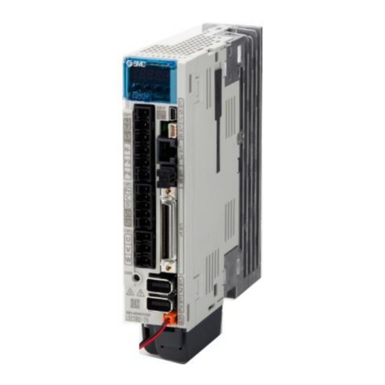
1. FUNCTIONS AND CONFIGURATION 1.7 Structure 1.7.1 Parts identification (1) LECSB2-T□ Detailed Name/Application explanation Display Section 4.5 The 5-digit, 7-segment LED shows the servo status and the alarm number. Operation section Used to perform status display, diagnostic, alarm, and parameter setting operations. Push the "MODE" and "SET" buttons at the same time for 3 s or more to switch to the one-touch tuning mode. -
Page 36: Configuration Including Peripheral Equipment
1. FUNCTIONS AND CONFIGURATION 1.8 Configuration including peripheral equipment Connecting a servo motor of the wrong axis to U, V, W, or CN2 of the driver may CAUTION cause a malfunction. POINT Equipment other than the driver and servo motor are optional or recommended products. - Page 37 1. FUNCTIONS AND CONFIGURATION Note 1. The power factor improving AC reactor can also be used. 2. For 1-phase 200 V AC to 240 V AC, connect the power supply to L1 and L3. Leave L2 open. For the power supply specifications, refer to section 1.3.
- Page 38 2. INSTALLATION 2. INSTALLATION ..............................2 2.1 Installation direction and clearances ......................3 2.2 Keep out foreign materials ........................4 2.3 Encoder cable stress ..........................5 2.4 Inspection items ............................5 2.5 Parts having service lives ..........................6 2.6 Restrictions when using this product at altitude exceeding 1000 m and up to 2000 m above sea level...6 2 - 1...
-
Page 39: Installation
2. INSTALLATION 2. INSTALLATION WARNING To prevent electric shock, ground each equipment securely. Stacking in excess of the specified number of product packages is not allowed. Do not hold the front cover, cable, or connector when carrying the driver. It may fall. -
Page 40: Installation Direction And Clearances
2. INSTALLATION 2.1 Installation direction and clearances The equipment must be installed in the specified direction. Otherwise, it may cause a malfunction. CAUTION Leave specified clearances between the driver and the cabinet walls or other equipment. Otherwise, it may cause a malfunction. (1) Installation clearances of the driver (a) Installation of one driver Cabinet... -
Page 41: Keep Out Foreign Materials
2. INSTALLATION (b) Installation of two or more drivers POINT Close mounting is possible depending on the capacity of the driver. Refer to section 1.3 for availability of close mounting. When mounting the drivers closely, do not install the driver whose depth is larger than that of the left side driver since CNP1, CNP2, and CNP3 connectors cannot be disconnected. -
Page 42: Encoder Cable Stress
2. INSTALLATION (3) When installing the cabinet in a place where toxic gas, dirt and dust exist, conduct an air purge (force clean air into the cabinet from outside to make the internal pressure higher than the external pressure) to prevent such materials from entering the cabinet. 2.3 Encoder cable stress (1) The way of clamping the cable must be fully examined so that bending stress and cable's own weight stress are not applied to the cable connection. -
Page 43: Parts Having Service Lives
2. INSTALLATION 2.5 Parts having service lives Service lives of the following parts are listed below. However, the service lives vary depending on operation and environment. If any fault is found in the parts, they must be replaced immediately regardless of their service lives. Part name Life guideline Smoothing capacitor... - Page 44 2. INSTALLATION (2) Input voltage Generally, a withstand voltage decreases as increasing altitude; however, there is no restriction on the withstand voltage. Use in the same manner as in 1000 m or less. (Refer to section 1.3.) (3) Parts having service life (a) Smoothing capacitor The capacitor will reach the end of its life in 10 years of continuous operation in air-conditioned environment (ambient temperature of 30 °C or less).
- Page 45 3. SIGNALS AND WIRING 3. SIGNALS AND WIRING ..........................2 3.1 Input power supply circuit ........................3 3.2 I/O signal connection example ........................6 3.2.1 Position control mode ...........................6 3.3 Explanation of power supply system ....................15 3.3.1 Signal explanations .........................15 3.3.2 Power-on sequence ..........................16 3.3.3 Wiring CNP1, CNP2, and CNP3 ....................17 3.4 Connectors and pin assignment ......................19 3.5 Signal (device) explanations .........................22...
- Page 46 3. SIGNALS AND WIRING 3. SIGNALS AND WIRING Any person who is involved in wiring should be fully competent to do the work. Before wiring, turn off the power and wait for 15 minutes or more until the charge lamp turns off. Then, confirm that the voltage between P+ and N- is safe with a voltage tester and others.
-
Page 47: Input Power Supply Circuit
3. SIGNALS AND WIRING Connecting a servo motor of the wrong axis to U, V, W, or CN2 of the driver may cause a malfunction. CAUTION Before wiring, switch operation, etc., eliminate static electricity. Otherwise, it may cause a malfunction. 3.1 Input power supply circuit Always connect a magnetic contactor between the power supply and the main circuit power supply (L1/L2/L3) of the driver, in order to configure a circuit that... - Page 48 3. SIGNALS AND WIRING Using 3-phase 200 V AC to 240 V AC power supply for LECSB2-T□ Malfunction Emergency stop switch Driver Servo amplifier Servo motor (Note 6) MCCB CNP1 (Note 10) 3-phase CNP3 (Note 5) 200 V AC to Motor 240 V AC (Note 9)
- Page 49 3. SIGNALS AND WIRING (2) Using 1-phase 200 V AC to 240 V AC power supply for LECSB2-T□ POINT Connect the 1-phase 200 V AC to 240 V AC power supply to L1 and L3. One of the connecting destinations is different from LECSB□-S□ Series Driver's. Malfunction Emergency stop switch Driver...
- Page 50 3. SIGNALS AND WIRING 3.2 I/O signal connection example 3.2.1 Position control mode (1) Sink I/O interface Driver Servo amplifier (Note 4) 24 V DC (Note 7) (Note 4) Positioning module 24 V DC RD75D/LD75D/QD75D (Note 7) DOCOM (Note 2) DICOM Malfunction (Note 6)
- Page 51 3. SIGNALS AND WIRING Note 1. To prevent an electric shock, always connect the protective earth (PE) terminal (marked ) of the driver to the protective earth (PE) of the cabinet. 2. Connect the diode in the correct direction. If it is connected reversely, the driver will malfunction and will not output signals, disabling EM2 (Forced stop 2) and other protective circuits.
- Page 52 3. SIGNALS AND WIRING (2) Source I/O interface POINT For notes, refer to (1) in this section. Driver Servo amplifier (Note 4, 14) 24 V DC (Note 7) (Note 4, 14) Positioning module 24 V DC RD75D/LD75D/QD75D (Note 7) DOCOM (Note 2) DICOM Malfunction...
- Page 53 3. SIGNALS AND WIRING 3.2.2 Speed control mode (1) Sink I/O interface Driver Servo amplifier (Note 7) (Note 4) 24 V DC DOCOM DOCOM (Note 2) 10 m or less Malfunction (Note 7) (Note 12) (Note 6) Main circuit power supply Zero speed Forced stop 2 (Note 3, 5)
- Page 54 3. SIGNALS AND WIRING Note 1. To prevent an electric shock, always connect the protective earth (PE) terminal (marked ) of the driver to the protective earth (PE) of the cabinet. 2. Connect the diode in the correct direction. If it is connected reversely, the driver will malfunction and will not output signals, disabling EM2 (Forced stop 2) and other protective circuits.
- Page 55 3. SIGNALS AND WIRING (2) Source I/O interface POINT For notes, refer to (1) in this section. Driver Servo amplifier (Note 7) (Note 4, 13) 24 V DC DOCOM DOCOM (Note 2) 10 m or less Malfunction (Note 7) (Note 12) (Note 6) Main circuit power supply Zero speed...
- Page 56 3. SIGNALS AND WIRING 3.2.3 Torque control mode POINT EM2 has the same function as EM1 in the torque control mode. (1) For sink I/O interface Driver Servo amplifier (Note 6) (Note 4) 24 V DC DOCOM DOCOM (Note 2) 10 m or less Malfunction (Note 6)
- Page 57 3. SIGNALS AND WIRING Note 1. To prevent an electric shock, always connect the protective earth (PE) terminal (marked ) of the driver to the protective earth (PE) of the cabinet. 2. Connect the diode in the correct direction. If it is connected reversely, the driver will malfunction and will not output signals, disabling EM2 (Forced stop 2) and other protective circuits.
- Page 58 3. SIGNALS AND WIRING (2) For source I/O interface POINT For notes, refer to (1) in this section. Driver Servo amplifier (Note 6) (Note 4, 11) 24 V DC DOCOM DOCOM (Note 2) 10 m or less Malfunction (Note 10) (Note 6) (Note 5) Main circuit power supply...
-
Page 59: Explanation Of Power Supply System
3. SIGNALS AND WIRING 3.3 Explanation of power supply system 3.3.1 Signal explanations POINT For the layout of connector and terminal block, refer to chapter 9 DIMENSIONS. Connection target Symbol Description (application) Supply the following power to L1, L2, and L3. For 1-phase 200 V AC to 240 V AC, connect the power supply to L1 and L3. -
Page 60: Power-On Sequence
3. SIGNALS AND WIRING 3.3.2 Power-on sequence POINT A voltage, output signal, etc. of analog monitor output may be irregular at power- (1) Power-on procedure 1) Always use a magnetic contactor for the main circuit power supply wiring (L1/L2/L3) as shown in above section 3.1. -
Page 61: Wiring Cnp1, Cnp2, And Cnp3
3. SIGNALS AND WIRING 3.3.3 Wiring CNP1, CNP2, and CNP3 POINT For the wire sizes used for wiring, refer to section 11.9. When wiring, remove the power connectors from the driver. Insert only one wire or ferrule to each wire insertion hole. Use the driver power supply connector for wiring CNP1, CNP2, and CNP3. - Page 62 3. SIGNALS AND WIRING (2) Cable connection procedure (a) Fabrication on cable insulator (a) Fabrication on cable insulator Refer to table 3.1 to 3.4 for stripped length of cable insulator. The appropriate stripped length of cables depends on their type, etc. Set the length considering their status. Insulator Core Stripped length...
-
Page 63: Connectors And Pin Assignment
3. SIGNALS AND WIRING 3.4 Connectors and pin assignment POINT The pin assignment of the connectors is as viewed from the cable connector wiring section. For the STO I/O signal connector (CN8), refer to chapter 13. For the CN1 connector, securely connect the external conductive portion of the shielded cable to the ground plate and fix it to the connector shell. - Page 64 3. SIGNALS AND WIRING The driver front view shown is that of the LECSB2-T7 or less. Refer to chapter 9 DIMENSIONS for the appearances and connector layouts of the other drivers. CN5 (USB connector) refer to section 11.7. 11.3 CN3 (RS-422/RS-485 connector) refer to chapter 14.
- Page 65 3. SIGNALS AND WIRING (Note 2) I/O signals in control modes (Note 1) Pin No. Related parameter P15R P15R P15R P15R P15R P15R -/VC VC/VLA VLA/- PP/- -/PP PD43/PD44 (Note 6) (Note 6) (Note 6) PG/- -/PG OPC/- -/OPC (Note 4) (Note 4) (Note 4) (Note 4)
-
Page 66: Signal (Device) Explanations
3. SIGNALS AND WIRING 3.5 Signal (device) explanations The pin numbers in the connector pin No. column are those in the initial status. For the I/O interfaces (symbols in I/O division column in the table), refer to section 3.9.2. The symbols in the control mode field of the table shows the followings. - Page 67 3. SIGNALS AND WIRING Control Connector mode Device Symbol Function and application pin No. division Forward rotation CN1-43 To start operation, turn on LSP and LSN. Turn it off to bring the motor to a DI-1 stroke end sudden stop and make it servo-locked. Setting [Pr.
- Page 68 3. SIGNALS AND WIRING Control Connector mode Device Symbol Function and application pin No. division Forward rotation CN1-18 This is used to select a servo motor torque generation directions. DI-1 selection The following shows the torque generation directions. (Note) Input device Torque generation direction Torque is not generated.
- Page 69 3. SIGNALS AND WIRING Control Connector mode Device Symbol Function and application pin No. division Proportion control CN1-17 Turn PC on to switch the speed amplifier from the proportional integral DI-1 type to the proportional type. If the servo motor at a stop is rotated even for a pulse due to any external factor, it generates torque to compensate for a position shift.
- Page 70 3. SIGNALS AND WIRING Control Connector mode Device Symbol Function and application pin No. division Control switching CN1-45 «Position/speed control change mode» DI-1 Refer to Function This is used to select the control mode in the position/speed control switching mode. application.
- Page 71 3. SIGNALS AND WIRING (b) Output device Control Connector mode Device Symbol Function and application pin No. division Malfunction CN1-48 When an alarm occurs, ALM will turn off. When an alarm does not occur, ALM will turn on after 2.5 s to 3.5 s after power-on.
- Page 72 3. SIGNALS AND WIRING Control Connector mode Device Symbol Function and application pin No. division Zero speed CN1-23 ZSP turns on when the servo motor speed is zero speed (50 r/min) or less. detection Zero speed can be changed with [Pr. PC17]. OFF level Forward 70 r/min...
- Page 73 3. SIGNALS AND WIRING Control Connector mode Device Symbol Function and application pin No. division During tough MTTR MTTR turns on when the instantaneous power failure tough drive operates drive while the tough drive function selection is enabled with [Pr. PA20]. CLDS Do not use it.
- Page 74 3. SIGNALS AND WIRING (3) Output signal Control Connector mode Device Symbol Function and application pin No. division Encoder A- CN1-4 The encoder output pulses set in [Pr. PA15] are outputted in the phase pulse differential line driver type. CN1-5 (differential line In CCW rotation of the servo motor, the encoder B-phase pulse lags the encoder A-phase pulse by a phase angle of π/2.
- Page 75 3. SIGNALS AND WIRING (5) Power supply Control Connector mode Device Symbol Function and application pin No. division Digital I/F DICOM CN1-20 Input 24 V DC (24 V DC ± 10% 500 mA) to I/O interface. The power power supply supply capacity changes depending on the number of I/O interface points CN1-21 input...
-
Page 76: Detailed Explanation Of Signals
3. SIGNALS AND WIRING 3.6 Detailed explanation of signals 3.6.1 Position control mode POINT Adjust the logic of a positioning module and command pulse as follows. MITSUBISHI ELECTRIC SYSTEM & SERVICE CO., LTD MELSEC iQ-R series/MELSEC-Q series/MELSEC-L series positioning module Command pulse logic setting Signal type LECSB2-T□driver [Pr. - Page 77 3. SIGNALS AND WIRING The following section explains about the case where the negative logic and the forward/reverse rotation pulse trains are set to "_ _ 1 0" in [Pr. PA13]. (ON) (ON) (ON) (OFF) (OFF) (OFF) Forward rotation pulse train (transistor) Reverse rotation pulse train (OFF)
- Page 78 3. SIGNALS AND WIRING (2) INP (In-position) INP turns on when the number of droop pulses in the deviation counter falls within the preset in-position range ([Pr. PA10]). INP may turn on continuously during a low-speed operation with a large value set as the in-position range.
- Page 79 3. SIGNALS AND WIRING (5) Torque limit If the torque limit is canceled during servo-lock, the servo motor may suddenly rotate according to position deviation in respect to the command position. CAUTION When using the torque limit, check that [Pr. PB06 Load to motor inertia ratio/load to motor mass ratio] is set properly.
- Page 80 3. SIGNALS AND WIRING Input device (Note 1) Enabled torque limit value Limit value status CCW power running/CW CW power running/CCW regeneration regeneration Pr. PA11 Pr .PA12 Pr. PA11 > Pr. PA11 Pr. PA12 Pr. PA12 Pr. PA11 < TLA (Note 2) TLA (Note 3) Pr.
-
Page 81: Speed Control Mode
3. SIGNALS AND WIRING 3.6.2 Speed control mode (1) Speed setting (a) Speed command and speed The servo motor is run at the speeds set in the parameters or at the speed set in the applied voltage of VC (Analog speed command). A relation between VC (Analog speed command) applied voltage and the servo motor speed is as follows. - Page 82 3. SIGNALS AND WIRING (b) SP1 (Speed selection 1), SP2 (Speed selection 2), and speed command value Select any of the speed settings by the internal speed commands 1 to 3 and by VC (Analog speed command) using SP1 (Speed selection 1) and SP2 (Speed selection 2) as follows. (Note) Input device Speed command value VC (Analog speed command)
-
Page 83: Torque Control Mode
3. SIGNALS AND WIRING 3.6.3 Torque control mode (1) Torque limit (a) Torque command and torque The following shows a relation between the applied voltage of TC (Analog torque command) and the torque by the servo motor. The maximum torque is generated at ±8 V. The speed at ±8 V can be changed with [Pr. PC13]. CCW direction Forward rotation Maximum torque... - Page 84 3. SIGNALS AND WIRING (b) Analog torque command offset Using [Pr. PC38], the offset voltage of -9999 mV to 9999 mV can be added to the TC applied voltage as follows. Maximum torque Torque [Pr. PC38] offset range -9999 mV to 9999 mV 8 (-8) TC applied voltage [V] (2) Torque limit...
- Page 85 3. SIGNALS AND WIRING Normally, connect as follows. Driver Servo amplifier (Note) 24 V DC DICOM P15R 2 kΩ 2 kΩ Japan resistor RRS10 or equivalent Note. This diagram shows sink I/O interface. For source I/O interface, refer to section 3.9.3.
-
Page 86: Position/Speed Control Switching Mode
3. SIGNALS AND WIRING 3.6.4 Position/speed control switching mode Set " _ _ _ 1" in [Pr. PA01] to switch to the position/speed control switching mode. This function is not available in the absolute position detection system. (1) LOP (control switching) Use LOP (Control switching) to switch between the position control mode and the speed control mode with an external contact. - Page 87 3. SIGNALS AND WIRING (3) Speed setting in speed control mode (a) Speed command and speed The servo motor is run at the speeds set in the parameters or at the speed set in the applied voltage of VC (Analog speed command). The relation between an applied voltage of VC (Analog speed command) and servo motor speed, and the rotation direction with turning on ST1/ST2 are the same as section 3.6.2 (1) (a).
-
Page 88: Speed/Torque Control Switching Mode
3. SIGNALS AND WIRING (c) SA (Speed reached) As in section 3.6.2 (2) 3.6.5 Speed/torque control switching mode Set " _ _ _ 3" in [Pr. PA01] to switch to the speed/torque control switching mode. (1) LOP (control switching) Use LOP (Control switching) to switch between the speed control mode and the torque control mode with an external contact. - Page 89 3. SIGNALS AND WIRING Normally, connect as follows. Driver Servo amplifier (Note) 24 V DC DICOM P15R 2 kΩ 2 kΩ Japan resistor RRS10 or equivalent Note. This diagram shows sink I/O interface. For source I/O interface, refer to section 3.9.3.
-
Page 90: Torque/Position Control Switching Mode
3. SIGNALS AND WIRING 3.6.6 Torque/position control switching mode Set " _ _ _ 5" in [Pr. PA01] to switch to the torque/position control switching mode. (1) LOP (control switching) Use LOP (Control switching) to switch between the torque control mode and the position control mode with an external contact. -
Page 91: Forced Stop Deceleration Function
3. SIGNALS AND WIRING 3.7 Forced stop deceleration function POINT When alarms not related to the forced stop function occur, control of motor deceleration cannot be guaranteed. (Refer to chapter 8.) In the torque control mode, the forced stop deceleration function is not available. If an alarm occurs with the forced stop deceleration function disabled, the servo motor will stop with the dynamic brake. - Page 92 3. SIGNALS AND WIRING (2) Timing chart POINT When LSP/LSN is turned on during a forced stop deceleration, the motor will stop depending on the setting of [Pr. PD30] as follows. [Pr. PD30] Stop system _ _ _ 0 Switching to sudden stop _ _ _ 1 Continuing forced stop deceleration When EM2 (Forced stop 2) is turned off, the motor will decelerate according to [Pr.
-
Page 93: Base Circuit Shut-Off Delay Time Function
3. SIGNALS AND WIRING 3.7.2 Base circuit shut-off delay time function The base circuit shut-off delay time function is used to prevent vertical axis from dropping at a forced stop (EM2 goes off) or alarm occurrence due to delay time of the electromagnetic brake. Use [Pr. PC16] to set the delay time between completion of EM2 (Forced stop 2) or activation of MBR (Electromagnetic brake interlock) due to an alarm occurrence, and shut-off of the base circuit. -
Page 94: Vertical Axis Freefall Prevention Function
3. SIGNALS AND WIRING 3.7.3 Vertical axis freefall prevention function The vertical axis freefall prevention function avoids machine damage by pulling up the shaft slightly like the following case. When the servo motor is used for operating vertical axis, the servo motor electromagnetic brake and the base circuit shut-off delay time function avoid dropping axis at forced stop. -
Page 95: Alarm Occurrence Timing Chart
3. SIGNALS AND WIRING 3.8 Alarm occurrence timing chart When an alarm has occurred, remove its cause, make sure that the operation CAUTION signal is not being input, ensure safety, and reset the alarm before restarting operation. POINT In the torque control mode, the forced stop deceleration function is not available. To deactivate an alarm, cycle the control circuit power, push the "SET"... -
Page 96: When You Do Not Use The Forced Stop Deceleration Function
3. SIGNALS AND WIRING (2) When the forced stop deceleration function is not enabled Alarm occurrence Braking by the dynamic brake Dynamic brake lock + Braking by the electromagnetic brake Servo motor speed 0 r/min Base circuit (Energy supply to the servo motor) Servo amplifier Driver display... -
Page 97: Interfaces
3. SIGNALS AND WIRING 3.9 Interfaces 3.9.1 Internal connection diagram POINT Refer to section 13.3.1 for the CN8 connector. Driver Servo amplifier (Note 1) (Note 5) 24 V DC (Note 1) DOCOM Approx. 6.2 k Ω SON SON SON DOCOM SP2 SP2 INP SA PC ST1 RS2 17... - Page 98 3. SIGNALS AND WIRING Note 1. P: Position control mode, S: Speed control mode, T: Torque control mode 2. This is for the differential line driver pulse train input. For the open-collector pulse train input, connect as follows. DOCOM DOCOM 24 V DC 24 V DC DICOM...
-
Page 99: Detailed Explanation Of Interfaces
3. SIGNALS AND WIRING 3.9.2 Detailed explanation of interfaces This section provides the details of the I/O signal interfaces (refer to the I/O division in the table) given in section 3.5. Refer to this section and make connection with the external device. (1) Digital input interface DI-1 This is an input circuit whose photocoupler cathode side is the input terminal. - Page 100 3. SIGNALS AND WIRING (2) Digital output interface DO-1 This is a circuit in which the collector of the output transistor is the output terminal. When the output transistor is turned on, the current will flow to the collector terminal. A lamp, relay or photocoupler can be driven.
- Page 101 3. SIGNALS AND WIRING (b) Open-collector type 1) Interface Driver Servo amplifier Max. input pulse frequency 200 kpulses/s 24 V DC Approximately 1.2 k Ω 2 m or less (Note) PP, NP DOCOM Note. Pulse train input interface is comprised of a photocoupler. If a resistor is connected to the pulse train signal line, it may malfunction due to reduction in current.
- Page 102 3. SIGNALS AND WIRING (b) Differential line driver type 1) Interface Maximum output current: 35 mA Driver Driver Servo amplifier Servo amplifier 100 Ω Am26LS32 or equivalent (LB, LZ) (LB, LZ) 150 Ω High-speed photocoupler (LBR, LZR) (LBR, LZR) 2) Output pulse Servo motor CCW rotation Time cycle (T) is determined by the settings of [Pr.
-
Page 103: Source I/O Interfaces
3. SIGNALS AND WIRING (6) Analog output Driver Servo amplifier (MO2) Output voltage: ±10 V (Note 1, 2) Maximum output current: 1 mA Resolution: 10 bits or equivalent Note 1. Output voltage range varies depending on the monitored signal. 3.9.3 Source I/O interfaces In this driver, source type I/O interfaces can be used. - Page 104 3. SIGNALS AND WIRING (2) Digital output interface DO-1 This is a circuit in which the emitter side of the output transistor is the output terminal. When the output transistor is turned on, the current flows from the output terminal to a load. A maximum of 2.6 V voltage drop occurs in the driver.
-
Page 105: Servo Motor With A Lock
3. SIGNALS AND WIRING 3.10 Servo motor with a lock 3.10.1 Safety precautions Configure an electromagnetic brake circuit which is interlocked with an external emergency stop switch. Contacts must be opened when ALM (Malfunction) Contacts must be opened when ALM (Malfunction) Contacts must be opened with the and MBR (Electromagnetic brake interlock) turns or MBR (Electromagnetic brake interlock) turns off. - Page 106 3. SIGNALS AND WIRING (2) Setting (a) Enable MBR (Electromagnetic brake interlock) with [Pr. PD23] to [Pr. PD26], [Pr. PD28], and [Pr. PD47]. (b) In [Pr. PC16 Electromagnetic brake sequence output], set a delay time (Tb) from MBR (Electromagnetic brake interlock) off to base circuit shut-off at a servo-off as in the timing chart in section 3.10.2 (1).
-
Page 107: Timing Chart
3. SIGNALS AND WIRING 3.10.2 Timing chart (1) When you use the forced stop deceleration function POINT To enable the function, set "2 _ _ _ (initial value)" in [Pr. PA04]. (a) Servo-on command (from PC or PLC…etc) on/off When SON (Servo-on) is turned off, the servo lock will be released after Tb [ms], and the servo motor will coast. - Page 108 3. SIGNALS AND WIRING (b) Forced stop 2 on/off POINT In the torque control mode, the forced stop deceleration function is not available. Keep SON (Servo-on) on while EM2 (Forced stop 2) is off. If SON (Servo-on) is turned off earlier than EM2 (Forced stop 2), the driver operates in the same way as (1) (a) in this section.
- Page 109 3. SIGNALS AND WIRING (c) Alarm occurrence 1) When the forced stop deceleration function is enabled Alarm occurrence Model speed command 0 Servo motor speed and equal to or less than zero speed (Note) 0 r/min Command is not received. Tb [Pr.
- Page 110 3. SIGNALS AND WIRING (e) Main circuit power supply off during control circuit power supply on POINT In the torque control mode, the forced stop deceleration function is not available. Forced stop deceleration Dynamic brake Dynamic brake The time until a voltage Servo motor speed + Electromagnetic brake lock...
- Page 111 3. SIGNALS AND WIRING (c) Alarm occurrence The operation status during an alarm is the same as section 3.8.2. (d) Both main and control circuit power supplies off It is the same as (1) (d) in this section. (e) Main circuit power supply off during control circuit power supply on Dynamic brake Dynamic brake + Electromagnetic brake...
-
Page 112: Wiring Diagrams (Le-□-□ Series Servo Motor)
3. SIGNALS AND WIRING 3.10.3 Wiring diagrams (LE-□-□ series servo motor) (1) When cable length is 10m or less 10m or less 10m以下 MR-BKS1CBL□M-A1-L MR-BKS1CBL□M-A2-L MR-BKS1CBL□M-A1-H Servo motor (Note3) サーボモータ (注3) LE-CSB-□□□ 電磁ブレーキ MR-BKS1CBL□M-A2-H 24VDC power 電磁ブレーキ用 Electoromagnetic Trouble (注2) (Note2) インタロック... -
Page 113: Grounding
3. SIGNALS AND WIRING 3.11 Grounding Ground the driver and servo motor securely. WARNING To prevent an electric shock, always connect the protective earth (PE) terminal (marked ) of the driver to the protective earth (PE) of the cabinet. The driver switches the power transistor on-off to supply power to the servo motor. Depending on the wiring and ground cable routing, the driver may be affected by the switching noise (due to di/dt and dv/dt) of the transistor. - Page 114 4. STARTUP 4. STARTUP ..............................2 4.1 Switching power on for the first time .....................3 4.1.1 Startup procedure ..........................3 4.1.2 Wiring check ............................4 4.1.3 Surrounding environment ........................5 4.2 Startup in position control mode ......................6 4.2.1 Power on and off procedures ......................6 4.2.2 Stop ..............................6 4.2.3 Test operation............................7 4.2.4 Parameter setting ..........................7...
- Page 115 4. STARTUP 4. STARTUP When executing a test run, follow the notice and procedures in this instruction manual. Otherwise, it may cause a malfunction, damage to the machine, or injury. WARNING Do not operate the switches with wet hands. Otherwise, it may cause an electric shock.
-
Page 116: Switching Power On For The First Time
4. STARTUP 4.1 Switching power on for the first time When switching power on for the first time, follow this section to make a startup. 4.1.1 Startup procedure Wiring check Check whether the driver and servo motor are wired correctly using visual inspection, DO forced output function (section 4.5.1), etc. -
Page 117: Wiring Check
4. STARTUP 4.1.2 Wiring check (1) Power supply system wiring Before switching on the main circuit and control circuit power supplies, check the following items. (a) Power supply system wiring 1) The power supplied to the power input terminals (L1/L2/L3/L11/L21) of the driver should satisfy the defined specifications. -
Page 118: Surrounding Environment
4. STARTUP (c) When option and auxiliary equipment are used a) When you use a regenerative option The lead wire between P+ terminal and D terminal should not be connected. The regenerative option should be connected to P+ terminal and C terminal. Twisted wires should be used. -
Page 119: Startup In Position Control Mode
4. STARTUP 4.2 Startup in position control mode Make a startup in accordance with section 4.1. This section provides the methods specific to the position control mode. 4.2.1 Power on and off procedures (1) Power-on Switch power on in the following procedure. Always follow this procedure at power-on. 1) Switch off SON (Servo-on). -
Page 120: Test Operation
4. STARTUP 4.2.3 Test operation Before starting actual operation, perform test operation to make sure that the machine operates normally. Refer to section 4.2.1 for the power on and off methods of the driver. Test operation of the servo motor In this step, confirm that the driver and servo motor operate normally. -
Page 121: Trouble At Start-Up
4. STARTUP 4.2.6 Trouble at start-up Never adjust or change the parameter values extremely as it will make operation CAUTION unstable. POINT Using the optional Setup software (MR Configurator2 ), you can refer to reason for rotation failure, etc. The following faults may occur at start-up. If any of such faults occurs, take the corresponding action. (1) Troubleshooting Start-up sequence Fault... - Page 122 4. STARTUP (2) How to find the cause of position shift PC or PLC...etc Driver Controller Servo amplifier Machine (a) Output pulse counter Servo motor Electronic gear [Pr. PA05], [Pr. PA06], (d) Machine stop position M [Pr. PA07], [Pr. PA21] (b) Cumulative command pulses Cause B Cause A...
-
Page 123: Startup In Speed Control Mode
4. STARTUP Check for a position mismatch in the following sequence. 1) When Q ≠ P Noise entered the pulse train signal wiring between the PC or PLC...etc and driver, causing command input pulses to be miscounted. (Cause A) Make the following check or take the following measures. Check how the shielding is done. -
Page 124: Stop
4. STARTUP 4.3.2 Stop Turn off SON (Servo-on) after the servo motor has stopped, and then switch the power off. If any of the following situations occurs, the driver suspends the running of the servo motor and brings it to a stop. -
Page 125: Test Operation
4. STARTUP 4.3.3 Test operation Before starting actual operation, perform test operation to make sure that the machine operates normally. Refer to section 4.3.1 for the power on and off methods of the driver. Test operation of the servo motor In this step, confirm that the driver and servo motor operate normally. -
Page 126: Parameter Setting
4. STARTUP 4.3.4 Parameter setting When using this servo in the speed control mode, change [Pr. PA01] setting to select the speed control mode. In the speed control mode, the servo can be used by merely changing the basic setting parameters ([Pr. - Page 127 4. STARTUP Start-up sequence Fault Investigation Possible cause Reference Switch on SON Alarm occurs. Refer to chapter 8 and remove cause. Chapter 8 (Servo-on). Servo motor shaft is 1. Check the display to see if 1. SON (Servo-on) is not input. Section not servo-locked.
-
Page 128: Startup In Torque Control Mode
4. STARTUP 4.4 Startup in torque control mode Make a startup in accordance with section 4.1. This section provides the methods specific to the torque control mode. 4.4.1 Power on and off procedures (1) Power-on Switch power on in the following procedure. Always follow this procedure at power-on. 1) Switch off SON (Servo-on). -
Page 129: Test Operation
4. STARTUP 4.4.3 Test operation Before starting actual operation, perform test operation to make sure that the machine operates normally. Refer to section 4.4.1 for the power on and off methods of the driver. Test operation of the servo motor In this step, confirm that the driver and servo motor operate normally. -
Page 130: Trouble At Start-Up
4. STARTUP 4.4.6 Trouble at start-up Never adjust or change the parameter values extremely as it will make unstable CAUTION movement. POINT Using the optional Setup software (MR Configurator2 ), you can refer to reason for rotation failure, etc. The following faults may occur at start-up. If any of such faults occurs, take the corresponding action. Start-up sequence Fault Investigation... -
Page 131: Display And Operation Sections
4. STARTUP 4.5 Display and operation sections 4.5.1 Summary The LECSB2-T□ driver has the display section (5-digit, 7-segment LED) and operation section (4 pushbuttons) for driver status display, alarm display, parameter setting, etc. Also, press the "MODE" and "SET" buttons at the same time for 3 s or more to switch to the one-touch tuning mode. The operation section and display data are described below. -
Page 132: Display Flowchart
4. STARTUP 4.5.2 Display flowchart Press the "MODE" button once to shift to the next display mode. Refer to section 4.5.3 and later for the description of the corresponding display mode. To refer to and set the gain/filter parameters, extension setting parameters and I/O setting parameters, enable them with [Pr. -
Page 133: Status Display Mode
4. STARTUP 4.5.3 Status display mode The servo status during operation is shown on the 5-digit, 7-segment LED display. Press the "UP" or "DOWN" button to change display data as desired. When the required data is selected, the corresponding symbol is displayed. Press the "SET" button to display that data. At only power-on, however, data appears after the symbol of the status display selected in [Pr. - Page 134 4. STARTUP Display examples The following table shows the display examples. Displayed data Item State Driver display Forward rotation at 2500 r/min Servo motor speed Reverse rotation at 3000 r/min Reverse rotation is indicated by "- ". Load to motor inertia ratio 7.00 times 11252 rev ABS counter -12566 rev...
- Page 135 4. STARTUP (3) Status display list The following table lists the servo statuses that may be shown. Refer to app. 7.3 for the measurement point. Status display Symbol Unit Description Feedback pulses from the servo motor encoder are counted and displayed. The values in excess of ±99999 can be counted.
- Page 136 4. STARTUP Status display Symbol Unit Description The estimated ratio of the load inertia moment to the servo motor shaft inertia Load to motor inertia ratio Multiplier moment is displayed. Bus voltage The voltage of main circuit converter (between P+ and N-) is displayed. Internal temperature of °C Inside temperature of encoder detected by the encoder is displayed.
-
Page 137: Diagnostic Mode
4. STARTUP 4.5.4 Diagnostic mode Name Display Description Not ready Indicates that the driver is being initialized or an alarm has occurred. Sequence Ready Indicates that the servo was switched on after completion of initialization and the driver is ready to operate. Drive recorder enabled When an alarm occurs in the status, the drive recorder will operate and write the status of... - Page 138 4. STARTUP Name Display Description Indicates the version of the software. Software version – Lower Indicates the system number of the software. Software version - Upper If offset voltages in the analog circuits inside and outside the driver cause the servo motor to rotate slowly at VC (Analog speed command) or VLA (Analog speed limit) of 0 V, this function automatically makes zero-...
-
Page 139: Alarm Mode
4. STARTUP 4.5.5 Alarm mode The current alarm, past alarm history and parameter error are displayed. The lower 3 digits on the display indicate the alarm number that has occurred or the parameter number in error. Name Display Description Indicates no occurrence of an alarm. Current alarm Indicates the occurrence of [AL. -
Page 140: Parameter Mode
4. STARTUP Functions at occurrence of an alarm (1) Any mode screen displays the current alarm. (2) Even during alarm occurrence, the other screen can be viewed by pressing the button in the operation area. At this time, the decimal point in the fourth digit remains blinking. (3) For any alarm, remove its cause and clear it in any of the following methods. - Page 141 4. STARTUP (2) Operation example (a) Parameters of 5 or less digits The following example shows the operation procedure performed after power-on to change the control mode to the speed control mode with [Pr. PA01 Operation mode]. Press "MODE" to switch to the basic setting parameter screen.
-
Page 142: External I/O Signal Display
4. STARTUP 4.5.7 External I/O signal display POINT The I/O signal settings can be changed using the I/O setting parameters [Pr. PD23] to [Pr. PD26], [Pr. PD28], and [Pr. PD47]. The on/off states of the digital I/O signals connected to the driver can be confirmed. (1) Operation Call the display screen shown after power-on. - Page 143 4. STARTUP (a) Control modes and I/O signals Signal (Note 2) Symbols of I/O signals in control modes input/output Connector Pin No. Related parameter (Note 1) I/O PP/- (Note 5) (Note 5) (Note 5) -/PP PD43/PD44 (Note 3) (Note 3) (Note 3) (Note 3) (Note 3)
- Page 144 4. STARTUP (3) Display data at initial values (a) Position control mode PC (CN1-17) NP (CN1-35)/ NP2 (CN1-38) CR (CN1-41) TL (CN1-18) RES (CN1-19) LOP (CN1-45) SON (CN1-15) PP (CN1-10)/ LSN (CN1-44) PP2 (CN1-37) EM2 (CN1-42) LSP (CN1-43) Light on: on Input signal Light off: off Output signals...
-
Page 145: Output Signal (Do) Forced Output
4. STARTUP 4.5.8 Output signal (DO) forced output POINT When the servo system is used in a vertical lift application, turning on MBR (Electromagnetic lock interlock) by the DO forced output after assigning it to connector CN1 will release the electromagnetic lock, causing a drop. Take drop preventive measures on the machine side. -
Page 146: Test Operation Mode
4. STARTUP 4.5.9 Test operation mode The test operation mode is designed for checking servo operation. Do not use it CAUTION for actual operation. If the servo motor operates unexpectedly, use EM2 (Forced stop 2) to stop it. POINT The test operation mode cannot be used in the absolute position detection system by DIO ([Pr. - Page 147 4. STARTUP (2) JOG operation POINT When performing JOG operation, turn on EM2, LSP and LSN. LSP and LSN can be set to automatic on by setting [Pr. PD01] to " _ C _ _ ". JOG operation can be performed when there is no command from the PC or PLC...etc. (a) Operation The servo motor rotates while holding down the "UP"...
- Page 148 4. STARTUP (3) Positioning operation POINT Setup software (MR Configurator2 ) is required to perform positioning operation. Turn on EM2 (forced stop 2) when performing positioning operation. Positioning operation can be performed when there is no command from a PC or PLC...etc. (a) Operation a) Motor speed [r/min] Enter the servo motor speed into the "Motor speed"...
- Page 149 4. STARTUP e) Move till Z-phase signal Travel is made until the travel distance is reached and the first Z-phase signal in the travelling direction turns on. f) Travel distance unit selection Select with the option buttons whether the travel distance set in c) is in the command pulse unit or in the encoder pulse unit.
- Page 150 4. STARTUP (4) Motor-less operation Without connecting the servo motor, output signals or status display can be provided in response to the input device as if the servo motor is actually running. This operation can be used to check the sequence of a PC or PLC...etc or the like.
- Page 151 5. PARAMETERS 5. PARAMETERS ..............................2 5.1 Parameter list ............................2 5.1.1 Basic setting parameters ([Pr. PA_ _ ]) ...................3 5.1.2 Gain/filter setting parameters ([Pr. PB_ _ ]) ...................4 5.1.3 Extension setting parameters ([Pr. PC_ _ ]) ..................6 5.1.4 I/O setting parameters ([Pr. PD_ _ ]) ....................8 5.1.5 Extension setting 2 parameters ([Pr.
-
Page 152: Parameter List
5. PARAMETERS 5. PARAMETERS Never make a drastic adjustment or change to the parameter values as doing so will make the operation unstable. CAUTION If fixed values are written in the digits of a parameter, do not change these values. Do not change parameters for manufacturer setting. - Page 153 5. PARAMETERS 5.1.1 Basic setting parameters ([Pr. PA_ _ ]) Operation Control mode mode Initial Symbol Name Unit value PA01 *STY Operation mode 1000h PA02 *REG Regenerative option 0000h PA03 *ABS Absolute position detection system 0000h PA04 *AOP1 Function selection A-1 2000h PA05 *FBP...
- Page 154 5. PARAMETERS 5.1.2 Gain/filter setting parameters ([Pr. PB_ _ ]) Operation Control mode mode Initial Symbol Name Unit value PB01 FILT Adaptive tuning mode (adaptive filter II) 0000h PB02 VRFT Vibration suppression control tuning mode (advanced vibration 0000h suppression control II) PB03 Position command acceleration/deceleration time constant [ms]...
- Page 155 5. PARAMETERS Operation Control mode mode Initial Symbol Name Unit value [rad/s] PB30 PG2B Position loop gain after gain switching PB31 VG2B Speed loop gain after gain switching [rad/s] PB32 VICB Speed integral compensation after gain switching [ms] PB33 VRF1B Vibration suppression control 1 - Vibration frequency after gain [Hz] switching...
- Page 156 5. PARAMETERS 5.1.3 Extension setting parameters ([Pr. PC_ _ ]) Operation Control mode mode Initial Symbol Name Unit value PC01 Acceleration time constant [ms] PC02 Deceleration time constant [ms] PC03 S-pattern acceleration/deceleration time constant [ms] PC04 Torque command time constant/thrust command time [ms] constant PC05...
- Page 157 5. PARAMETERS Operation Control mode mode Initial Symbol Name Unit value PC38 Analog torque command offset [mV] Analog torque limit offset PC39 Analog monitor 1 offset [mV] PC40 Analog monitor 2 offset [mV] PC41 For manufacturer setting PC42 PC43 Error excessive alarm detection level [rev] PC44 *COP9...
- Page 158 5. PARAMETERS 5.1.4 I/O setting parameters ([Pr. PD_ _ ]) Operation Control mode mode Initial Symbol Name Unit value PD01 *DIA1 Input signal automatic on selection 1 0000h PD02 For manufacturer setting 0000h PD03 *DI1L Input device selection 1L 0202h PD04 *DI1H Input device selection 1H...
- Page 159 5. PARAMETERS 5.1.5 Extension setting 2 parameters ([Pr. PE_ _ ]) Operation Control mode mode Initial Symbol Name Unit value PE01 *FCT1 Fully closed loop function selection 1 0000h PE02 For manufacturer setting 0000h PE03 *FCT2 Fully closed loop function selection 2 0003h PE04 *FBN...
- Page 160 5. PARAMETERS Operation Control mode mode Initial Symbol Name Unit value PE42 For manufacturer setting PE43 PE44 LMCP Lost motion compensation positive-side compensation value [0.01%] selection PE45 LMCN Lost motion compensation negative-side compensation [0.01%] value selection PE46 LMFLT Lost motion filter setting [0.1 ms] PE47 Torque offset...
- Page 161 5. PARAMETERS 5.1.6 Extension setting 3 parameters ([Pr. PF_ _ ]) Operation Control mode mode Initial Symbol Name Unit value PF01 For manufacturer setting 0000h PF02 0000h PF03 0000h PF04 PF05 PF06 0000h PF07 PF08 PF09 *FOP5 Function selection F-5 0000h PF10 For manufacturer setting...
-
Page 162: Basic Setting Parameters ([Pr. Pa
5. PARAMETERS 5.2 Detailed list of parameters POINT Set a value to each "x" in the "Setting digit" columns. 5.2.1 Basic setting parameters ([Pr. PA_ _ ]) Control Initial No./symbol/ Setting mode Function value name digit [unit] PA01 _ _ _ x Control mode selection *STY Select a control mode. - Page 163 5. PARAMETERS Control Initial No./symbol/ Setting mode Function value name digit [unit] PA02 _ _ x x Regenerative option *REG Select the regenerative option. Regenerative Incorrect setting may cause the regenerative option to burn. option If a selected regenerative option is not for use with the driver, [AL. 37 Parameter error] occurs.
- Page 164 5. PARAMETERS Control Initial No./symbol/ Setting mode Function value name digit [unit] PA03 _ _ _ x Absolute position detection system selection *ABS Set this digit when using the absolute position detection system in the position control mode. Absolute position 0: Disabled (incremental system) detection 1: Enabled (absolute position detection system by DIO)
- Page 165 5. PARAMETERS Initial No./symbol/ Setting Control Function value name digit mode [unit] PA06 Set the numerator of the electronic gear. To enable the parameter, set "Electronic gear selection" to "Electronic gear (0 _ _ _)", "J3 electronic gear setting value compatibility mode (2 _ _ _)", or "J2S Electronic electronic gear setting value compatibility mode (3 _ _ _)"...
- Page 166 5. PARAMETERS Control Initial No./symbol/ Setting mode Function value name digit [unit] PA08 _ _ _ x Gain adjustment mode selection Select the gain adjustment mode. Auto tuning 0: 2 gain adjustment mode 1 (interpolation mode) mode 1: Auto tuning mode 1 2: Auto tuning mode 2 3: Manual mode 4: 2 gain adjustment mode 2...
- Page 167 5. PARAMETERS Control Initial No./symbol/ Setting mode Function value name digit [unit] PA09 Set a response of the auto tuning. Machine characteristic Machine characteristic Auto tuning Guideline for Guideline for response Setting Setting machine machine value value Response Response resonance resonance frequency [Hz] frequency [Hz]...
- Page 168 5. PARAMETERS Control Initial No./symbol/ Setting mode Function value name digit [unit] PA13 _ _ _ x Command input pulse train form selection *PLSS 0: Forward/reverse rotation pulse train Command 1: Signed pulse train pulse input 2: A-phase/B-phase pulse train (The driver imports input pulses after multiplying by form four.) Refer to table 5.3 for settings.
- Page 169 5. PARAMETERS Control Initial No./symbol/ Setting mode Function value name digit [unit] PA13 Table 5.3 Command input pulse train form selection *PLSS Forward rotation Reverse rotation Command Setting Pulse train form (positive direction) (negative direction) pulse input value command command form Forward rotation pulse train...
- Page 170 5. PARAMETERS Control Initial No./symbol/ Setting mode Function value name digit [unit] PA14 Select command input pulses of the rotation direction. *POL Servo motor rotation direction/ Rotation linear servo motor travel direction Setting direction value selection When forward rotation When reverse rotation pulse is input pulse is input CCW or positive direction CW or negative direction...
- Page 171 5. PARAMETERS Control Initial No./symbol/ Setting mode Function value name digit [unit] PA18 Do not change this value. 0000h *MTY Servo motor type setting PA19 Select a reference range and writing range of the parameter. 00AAh *BLK Refer to table 5.4 for settings. Parameter writing inhibit Table 5.4 [Pr.
- Page 172 5. PARAMETERS Control Initial No./symbol/ Setting mode Function value name digit [unit] PA20 Alarms may not be avoided with the tough drive function depending on the situations of the power supply and load fluctuation. *TDS You can assign MTTR (During tough drive) to the pins CN1-22 to CN1-25, CN1-49, CN1-13, and CN1-14 with [Pr. Tough drive PD23] to [Pr.
- Page 173 5. PARAMETERS Control Initial No./symbol/ Setting mode Function value name digit [unit] PA23 _ _ x x Alarm detail No. setting DRAT Set the digits when you execute the trigger with arbitrary alarm detail No. for the drive recorder function. Drive recorder When these digits are "0 0", only the arbitrary alarm No.
-
Page 174: Gain/Filter Setting Parameters ([Pr. Pb
5. PARAMETERS 5.2.2 Gain/filter setting parameters ([Pr. PB_ _ ]) Control Initial No./symbol/ Setting mode Function value name digit [unit] PB01 _ _ _ x Filter tuning mode selection FILT Set the adaptive tuning. Adaptive Select the adjustment mode of the machine resonance suppression filter 1. Refer to tuning mode section 7.1.2 for details. - Page 175 5. PARAMETERS Control Initial No./symbol/ Setting mode Function value name digit [unit] PB03 Set the constant of a primary delay to the position command. [ms] You can select a control method from "Primary delay" or "Linear acceleration/deceleration" of "Position acceleration/deceleration filter type selection" Position in [Pr.
- Page 176 5. PARAMETERS Control Initial No./symbol/ Setting mode Function value name digit [unit] PB06 Set the load to motor inertia ratio or load to motor mass ratio. 7.00 Setting a value considerably different from the actual load moment of inertia or load [Multiplier] mass may cause an unexpected operation such as an overshoot.
- Page 177 5. PARAMETERS Control Initial No./symbol/ Setting mode Function value name digit [unit] PB08 Set the gain of the position loop. 37.0 [rad/s] Set this parameter to increase the position response to level load disturbance. Position loop Increasing the setting value will also increase the response level to the load gain disturbance but will be liable to generate vibration and noise.
- Page 178 5. PARAMETERS Control Initial No./symbol/ Setting mode Function value name digit [unit] PB14 Set the shape of the machine resonance suppression filter 1. NHQ1 When "Filter tuning mode selection" is set to "Automatic setting (_ _ _ 1)" in [Pr. PB01], this parameter will be adjusted automatically by adaptive tuning.
- Page 179 5. PARAMETERS Control Initial No./symbol/ Setting mode Function value name digit [unit] PB17 Set the shaft resonance suppression filter. This is used to suppress a low-frequency machine vibration. Shaft When "Shaft resonance suppression filter selection" is set to "Automatic setting (_ _ _ 0)" in [Pr. PB23], the value will resonance be calculated automatically from the servo motor you use and load to motor inertia ratio.
- Page 180 5. PARAMETERS Control Initial No./symbol/ Setting mode Function value name digit [unit] PB19 Set the vibration frequency for vibration suppression control 1 to suppress low- 100.0 frequency machine vibration. [Hz] VRF11 When "Vibration suppression control 1 tuning mode selection" is set to "Automatic Vibration setting (_ _ _ 1)"...
- Page 181 5. PARAMETERS Control Initial No./symbol/ Setting mode Function value name digit [unit] PB24 _ _ _ x Slight vibration suppression control selection *MVS Select the slight vibration suppression control. Slight 0: Disabled vibration 1: Enabled suppression To enable the slight vibration suppression control, set "Gain adjustment mode control selection"...
- Page 182 5. PARAMETERS Control Initial No./symbol/ Setting mode Function value name digit [unit] PB29 This is used to set the load to motor inertia ratio for when gain switching is enabled. 7.00 GD2B This parameter is enabled only when "Gain adjustment mode selection" is "Manual [Multiplier] mode (_ _ _ 3)"...
- Page 183 5. PARAMETERS Control Initial No./symbol/ Setting mode Function value name digit [unit] PB35 Set a damping of the vibration frequency for vibration suppression control 1 when 0.00 the gain switching is enabled. VRF3B This parameter will be enabled only when the following conditions are fulfilled. Vibration suppression "Gain adjustment mode selection"...
- Page 184 5. PARAMETERS Control Initial No./symbol/ Setting mode Function value name digit [unit] PB45 Set the command notch filter. CNHF _ _ x x Command notch filter setting frequency selection Command Refer to table 5.6 for the relation of setting values to frequency. notch filter _ x _ _ Notch depth selection Refer to table 5.7 for details.
- Page 185 5. PARAMETERS Control Initial No./symbol/ Setting mode Function value name digit [unit] PB46 Set the notch frequency of the machine resonance suppression filter 3. 4500 [Hz] To enable the setting value, set "Machine resonance suppression filter 3 selection" to "Enabled (_ _ _ 1)" in [Pr. PB47]. Machine resonance suppression...
- Page 186 5. PARAMETERS Control Initial No./symbol/ Setting mode Function value name digit [unit] PB51 Set the shape of the machine resonance suppression filter 5. NHQ5 When "Robust filter selection" is "Enabled (_ _ _ 1)" in [Pr. PE41], the machine resonance suppression filter 5 is not available.
- Page 187 5. PARAMETERS Control Initial No./symbol/ Setting mode Function value name digit [unit] PB56 Set the vibration frequency for vibration suppression control 2 when the gain switching is enabled. [Hz] VRF21B When you set a value less than 0.1 Hz, the value will be the same as [Pr. PB52]. Vibration suppression This parameter will be enabled only when the following conditions are fulfilled.
-
Page 188: Extension Setting Parameters ([Pr. Pc
5. PARAMETERS Control Initial No./symbol/ Setting mode Function value name digit [unit] PB60 Set the model loop gain when the gain switching is enabled. [rad/s] PG1B When you set a value less than 1.0 rad/s, the value will be the same as [Pr. PB07]. Model loop This parameter will be enabled only when the following conditions are fulfilled. - Page 189 5. PARAMETERS Control Initial No./symbol/ Setting mode Function value name digit [unit] PC03 Start/stop the servo motor smoothly. [ms] Set the time of the arc part for S-pattern acceleration/deceleration. S-pattern Setting "0" will make it linear acceleration/deceleration. acceleration/ deceleration Speed command time constant 0 r/min (0 mm/s)
- Page 190 5. PARAMETERS Control Initial No./symbol/ Setting mode Function value name digit [unit] PC06 Set the speed 2 of internal speed commands. [r/min]/ [mm/s] Internal Setting range: 0 to instantaneous permissible speed speed Set the speed 2 of internal speed limits. command 2 Internal speed limit 2...
- Page 191 5. PARAMETERS Control Initial No./symbol/ Setting mode Function value name digit [unit] PC13 Set the output torque at the analog torque command voltage (TC = ±8 V) of +8 V on 100.0 the assumption that the maximum torque/thrust is 100.0%. For example, set 50.0.
- Page 192 5. PARAMETERS Control Initial No./symbol/ Setting mode Function value name digit [unit] PC14 _ _ x x Analog monitor 1 output selection MOD1 Select a signal to output to MO1 (Analog monitor 1). Refer to app. 7.3 for detection point of output selection. Analog monitor 1 Refer to table 5.8 or table 5.9 for settings.
- Page 193 5. PARAMETERS Control Initial No./symbol/ Setting mode Function value name digit [unit] PC15 _ _ x x Analog monitor 2 output selection MOD2 Select a signal to output to MO2 (Analog monitor 2). Refer to app. 7.3 for detection point of output selection. Analog monitor 2 Refer to [Pr.
- Page 194 5. PARAMETERS Control Initial No./symbol/ Setting mode Function value name digit [unit] PC19 _ _ _ x Encoder output pulse phase selection *ENRS Select the encoder pulse direction. Encoder 0: A-phase 90° shift in CCW output pulse 1: A-phase 90° shift in CW selection Servo motor rotation direction/ Setting...
- Page 195 5. PARAMETERS Control Initial No./symbol/ Setting mode Function value name digit [unit] PC22 _ _ _ x For manufacturer setting *COP1 _ _ x _ Function _ x _ _ selection C-1 x _ _ _ Encoder cable communication method selection (Do not change this value.) PC23 _ _ _ x Servo-lock selection at speed control stop...
- Page 196 5. PARAMETERS Control Initial No./symbol/ Setting mode Function value name digit [unit] PC26 _ _ _ x [AL. 99 Stroke limit warning] selection *COP5 Enable or disable [AL. 99 Stroke limit warning]. Function 0: Enabled selection C-5 1: Disabled _ _ x _ For manufacturer setting _ x _ _ x _ _ _ PC27...
- Page 197 5. PARAMETERS Control Initial No./symbol/ Setting mode Function value name digit [unit] PC32 To enable the parameter, select "Electronic gear (0 _ _ _)", "J3 electronic gear setting value compatibility mode (2 _ _ _)" in [Pr. PA21]. CMX2 Commanded pulse multiplication Setting range: 1 to 16777215...
- Page 198 5. PARAMETERS Control Initial No./symbol/ Setting mode Function value name digit [unit] PC36 _ _ x x Status display selection at power-on *DMD Select a status display shown at power-on. Setting "21" to "27" will trigger [AL. 37] in the mode other than the positioning mode. Status display 00: Cumulative feedback pulses...
- Page 199 5. PARAMETERS Control Initial No./symbol/ Setting mode Function value name digit [unit] PC37 Set the offset voltage of VC (Analog speed command). The value For example, if CCW rotation or positive direction travel is provided by switching on differs ST1 (Forward rotation start) while applying 0 V to VC, set a negative value. Analog speed depending command...
- Page 200 5. PARAMETERS Control Initial No./symbol/ Setting mode Function value name digit [unit] PC45 _ _ _ X Do not change this value. *COPA Function _ _ X _ For manufacturer setting selection C-A _ X _ _ Do not change this value. X _ _ _ For manufacturer setting PC51 Set deceleration time constant when you use the forced stop deceleration function.
- Page 201 5. PARAMETERS Control Initial No./symbol/ Setting mode Function value name digit [unit] PC54 Set the compensation amount of the vertical axis freefall prevention function. [0.0001 RSUP1 Set it per servo motor rotation amount. rev] Vertical axis When setting a positive value, the servo motor moves in the direction set with [Pr. freefall PA14] for the forward rotation pulse input.
-
Page 202: I/O Setting Parameters ([Pr. Pd
5. PARAMETERS 5.2.4 I/O setting parameters ([Pr. PD_ _ ]) Control Initial No./symbol/ Setting mode Function value name digit [unit] PD01 Select input devices to turn on them automatically. *DIA1 _ _ _ x _ _ _ x (BIN): For manufacturer setting Input signal (HEX) _ _ x _ (BIN): For manufacturer setting... - Page 203 5. PARAMETERS Control Initial No./symbol/ Setting mode Function value name digit [unit] PD03 Any input device can be assigned to the CN1-15 pin. *DI1L _ _ x x Position control mode - Device selection Input device Refer to table 5.10. selection 1L x x _ _ Speed control mode - Device selection...
- Page 204 5. PARAMETERS Control Initial No./symbol/ Setting mode Function value name digit [unit] PD07 Any input device can be assigned to the CN1-17 pin. *DI3L When "_ _ _ 1" is set in [Pr. PA03] and absolute position detection system by DIO is selected, the CN1-17 pin will become ABSM (ABS transfer mode).
- Page 205 5. PARAMETERS Control Initial No./symbol/ Setting mode Function value name digit [unit] PD20 Any input device can be assigned to the CN1-44 pin. *DI9H _ _ x x Torque control mode - Device selection Input device Refer to table 5.10 in [Pr. PD03] for settings. selection 9H x x _ _ For manufacturer setting...
- Page 206 5. PARAMETERS Control Initial No./symbol/ Setting mode Function value name digit [unit] PD24 _ _ x x Device selection *DO2 Any output device can be assigned to the CN1-23 pin. Output device When "Enabled (absolute position detection system by DIO) (_ _ _ 1)" is selected in selection 2 [Pr.
- Page 207 5. PARAMETERS Control Initial No./symbol/ Setting mode Function value name digit [unit] PD30 _ _ _ x Stop method selection for LSP (Forward rotation stroke end) off and LSN (Reverse rotation stroke end) off *DOP1 Select a stop method for LSP (Forward rotation stroke end) off and LSN (Reverse Function rotation stroke end) off.
- Page 208 5. PARAMETERS Control Initial No./symbol/ Setting mode Function value name digit [unit] PD34 _ _ _ x Alarm code output *DOP5 Select output status of alarm codes. Function Alarm codes are outputted to the pins CN1-22, CN1-23, and CN1-24. selection D-5 0: Disabled 1: Enabled For details of the alarm codes, refer to chapter 8.
- Page 209 5. PARAMETERS Control Initial No./symbol/ Setting mode Function value name digit [unit] PD45 Any input device can be assigned to the CN1-35 pin/CN1-38 pin. *DI12L Setting "00" will assign NP/NP2 (reverse rotation pulse). Input device selection 12L _ _ x x Position control mode - Device selection The setting is disabled.
-
Page 210: Extension Setting 2 Parameters ([Pr. Pe
5. PARAMETERS 5.2.5 Extension setting 2 parameters ([Pr. PE_ _ ]) Control Initial No./symbol/ Setting mode Function value name digit [unit] PE01 _ _ _ x Do not change this value. *FCT1 _ _ x _ For manufacturer setting _ x _ _ x _ _ _ PE03 _ _ x x... - Page 211 5. PARAMETERS Control Initial No./symbol/ Setting mode Function value name digit [unit] PE05 Do not change this value. *FBD PE06 Do not change this value. [r/min] PE07 Do not change this value. [kpulse] PE08 Do not change this value. [rad/s] PE10 _ _ _ x For manufacturer setting FCT3...
- Page 212 5. PARAMETERS Control Initial No./symbol/ Setting mode Function value name digit [unit] PE41 _ _ _ x Robust filter selection EOP3 0: Disabled Function 1: Enabled selection E-3 When you select "Enabled" of this digit, the machine resonance suppression filter 5 set in [Pr.
-
Page 213: Extension Setting 3 Parameters ([Pr. Pf
5. PARAMETERS Control Initial No./symbol/ Setting mode Function value name digit [unit] PE50 Set the lost motion compensation non-sensitive band. When the fluctuation of the droop pulse is the setting value or less, the speed will be 0. Setting can be changed LMCT [pulse]/ in [Pr. - Page 214 5. PARAMETERS Control Initial No./symbol/ Setting mode Function value name digit [unit] PF21 Set a drive recorder switching time. When a USB communication is cut during using a graph function or a graph function is terminated, the function will be changed to the drive recorder function after the Drive settling time of this parameter.
- Page 215 5. PARAMETERS Control Initial No./symbol/ Setting mode Function value name digit [unit] PF31 Set a servo motor speed that divides a friction estimation area into high and low during the friction estimation process of the machine diagnosis. [r/min]/ FRIC [mm/s] Setting "0"...
- Page 216 6. NORMAL GAIN ADJUSTMENT 6. NORMAL GAIN ADJUSTMENT .........................2 6.1 Different adjustment methods ........................2 6.1.1 Adjustment on a single driver ......................2 6.1.2 Adjustment using setup software (MR Configurator2 ) ..............3 6.2 One-touch tuning .............................4 6.2.1 One-touch tuning flowchart ......................6 6.2.2 Display transition and operation procedure of one-touch tuning ..........9 6.2.3 Caution for one-touch tuning ......................23 6.3 Auto tuning ............................24 6.3.1 Auto tuning mode ..........................24...
-
Page 217: Normal Gain Adjustment
6. NORMAL GAIN ADJUSTMENT 6. NORMAL GAIN ADJUSTMENT POINT In the torque control mode, you do not need to make gain adjustment. Before making gain adjustment, check that your machine is not being operated at maximum torque of the servo motor. If operated over maximum torque, the machine may vibrate and may operate unexpectedly. -
Page 218: Adjustment Using Setup Software (Mr Configurator2 Tm )
6. NORMAL GAIN ADJUSTMENT (2) Adjustment sequence and mode usage Start Interpolation 2 gain adjustment mode 1 made for 2 or more (interpolation mode) axes? The load fluctuation is large during driving? One-touch tuning Handle the error Error handling Finished normally? Auto tuning mode 1 is possible? Adjustment OK? -
Page 219: One-Touch Tuning
6. NORMAL GAIN ADJUSTMENT 6.2 One-touch tuning POINT After the one-touch tuning is completed, "Gain adjustment mode selection" in [Pr. PA08] will be set to "2 gain adjustment mode 2 (_ _ _ 4)". To estimate [Pr. PB06 Load to motor inertia ratio/load to motor mass ratio], set "Gain adjustment mode selection"... - Page 220 6. NORMAL GAIN ADJUSTMENT The following parameters are set automatically with one-touch tuning. Also, "Gain adjustment mode selection" in [Pr. PA08] will be "2 gain adjustment mode 2 (_ _ _ 4)" automatically. Other parameters will be set to an optimum value depending on the setting of [Pr. PA09 Auto tuning response]. Table 6.1 List of parameters automatically set with one-touch tuning Parameter Symbol...
-
Page 221: One-Touch Tuning Flowchart
6. NORMAL GAIN ADJUSTMENT 6.2.1 One-touch tuning flowchart (1) User command method (a) When you use setup software (MR Configurator2 Make one-touch tuning as follows. Start Start a system referring to chapter 4. Startup of the system Rotate the servo motor by a controller. (In the user command method, the one-touch tuning Operation cannot be executed if the servo motor is not operating.) One-touch tuning start,... - Page 222 6. NORMAL GAIN ADJUSTMENT (b) When you use push buttons Make one-touch tuning as follows. Start Start a system referring to chapter 4. Startup of the system Rotate the servo motor by a controller. (In the user command method, the one-touch tuning Operation cannot be executed if the servo motor is not operating.) Push the "MODE"...
- Page 223 6. NORMAL GAIN ADJUSTMENT (2) Driver command method Make one-touch tuning as follows. Start Start a system referring to chapter 4. Startup of the system Move the moving part to the center of a movable range. Movement to tuning start position Start one-touch tuning of setup software (MR Configurator2 ), and select "Driver command One-touch tuning start,...
-
Page 224: Display Transition And Operation Procedure Of One-Touch Tuning
6. NORMAL GAIN ADJUSTMENT 6.2.2 Display transition and operation procedure of one-touch tuning (1) When you use setup software (MR Configurator2 (a) Command method selection Select a command method from two methods in the one-touch tuning window of setup software (MR Configurator2 6 - 9... - Page 225 6. NORMAL GAIN ADJUSTMENT 1) User command method It is recommended to input commands meeting the following conditions to the driver. If one-touch tuning is executed while commands which do not meet the conditions are inputted to the driver, the one-touch tuning error may occur. One cycle time Travel distance Forward...
- Page 226 6. NORMAL GAIN ADJUSTMENT 2) Driver command method Input a permissible travel distance. Input it in the load-side resolution unit for the fully closed loop control mode, and in the servo motor-side resolution unit for other control modes. In the driver command method, the servo motor will be operated in a range between "current value ±...
- Page 227 6. NORMAL GAIN ADJUSTMENT (b) Response mode selection Select a response mode from 3 modes in the one-touch tuning window of setup software (MR Configurator2 Table 6.2 Response mode explanations Response mode Explanation High mode This mode is for high-rigid system. Basic mode This mode is for standard system.
- Page 228 6. NORMAL GAIN ADJUSTMENT Refer to the following table for selecting a response mode. Table 6.3 Guideline for response mode Response mode Machine characteristic Response Low mode Basic mode High mode Guideline of corresponding machine Low response Arm robot General machine tool conveyor Precision working machine...
- Page 229 6. NORMAL GAIN ADJUSTMENT After one-touch tuning is executed using the driver command method, control will not be performed by commands from the controller. To return to the state in which control is performed from the controller, cycle the power. During processing of one-touch tuning, the progress will be displayed as follows.
- Page 230 6. NORMAL GAIN ADJUSTMENT After the one-touch tuning is completed, "0000" will be displayed at status in error code. In addition, settling time and overshoot amount will be displayed in "Adjustment result". (d) Stop of one-touch tuning During one-touch tuning, clicking the stop button stops one-touch tuning. If the one-touch tuning is stopped, "C000"...
- Page 231 6. NORMAL GAIN ADJUSTMENT (e) If an error occurs If a tuning error occurs during the one-touch tuning, the tuning will be stopped. With that, the following error code will be displayed in status. Check the cause of tuning error. When executing one- touch tuning again, stop the servo motor once.
- Page 232 6. NORMAL GAIN ADJUSTMENT Display Name Error detail Corrective action example C006 Driver command start One-touch tuning was attempted to start in Execute the one-touch tuning in the driver error the driver command method under the command method while the servo motor is following speed condition.
- Page 233 6. NORMAL GAIN ADJUSTMENT (h) Initializing one-touch tuning Clicking "Return to initial value" in the one-touch tuning window of setup software (MR Configurator2 ) enables to return the parameter to the initial value. Refer to table 6.1 for the parameters which you can initialize. Clicking "Return to value before adjustment"...
- Page 234 6. NORMAL GAIN ADJUSTMENT (2) When you use push buttons POINT Push the "MODE" and "SET" buttons at the same time for 3 s or more to switch to the response mode selection ("AUTO.") without going through the initial screen of the one-touch tuning ("AUTO"). When you use push buttons, one-touch tuning can be executed in the user command method only.
- Page 235 6. NORMAL GAIN ADJUSTMENT (b) One-touch tuning execution POINT For equipment in which overshoot during one-touch tuning is in the permissible level of the in-position range, changing the value of [Pr. PA25 One-touch tuning - Overshoot permissible level] will shorten the settling time and improve the response.
- Page 236 6. NORMAL GAIN ADJUSTMENT (d) If an error occurs Stop symbol If an error occurs during the one-touch tuning, the tuning will be forcibly terminated and the stop symbol and error code from "C 001" to "C 00F" will be displayed by turns with 2 s interval.
- Page 237 6. NORMAL GAIN ADJUSTMENT (g) Clearing one-touch tuning Refer to table 6.1 for the parameters which you can clear. You can initialize the parameters changed by the one-touch tuning with the clear mode. You can reset the parameters to before tuning with the back mode. 1) Switch to the initial screen "AUTO"...
-
Page 238: Caution For One-Touch Tuning
6. NORMAL GAIN ADJUSTMENT 6.2.3 Caution for one-touch tuning (1) Caution common for user command method and driver command method (a) The tuning is not available in the torque control mode. (b) The one-touch tuning cannot be executed while an alarm or warning which does not continue the motor driving is occurring. -
Page 239: Auto Tuning
6. NORMAL GAIN ADJUSTMENT 6.3 Auto tuning 6.3.1 Auto tuning mode The driver has a real-time auto tuning function which estimates the machine characteristic (load to motor inertia ratio) in real time and automatically sets the optimum gains according to that value. This function permits ease of gain adjustment of the driver. -
Page 240: Auto Tuning Mode Basis
6. NORMAL GAIN ADJUSTMENT 6.3.2 Auto tuning mode basis The block diagram of real-time auto tuning is shown below. Load moment Automatic setting of inertia Encoder Loop gain Command Current PG1, PG2, control VG2, VIC Servo motor Current feedback Real-time Position/speed Set 0 or 1 to turn on. -
Page 241: Adjustment Procedure By Auto Tuning
6. NORMAL GAIN ADJUSTMENT 6.3.3 Adjustment procedure by auto tuning Since auto tuning is enabled before shipment from the factory, simply running the servo motor automatically sets the optimum gains that match the machine. Merely changing the response level setting value as required completes the adjustment. -
Page 242: Response Level Setting In Auto Tuning Mode
6. NORMAL GAIN ADJUSTMENT 6.3.4 Response level setting in auto tuning mode Set the response of the whole servo system by [Pr. PA09]. As the response level setting is increased, trackability to a command improves and settling time decreases, but setting the response level too high will generate vibration. -
Page 243: Manual Mode
6. NORMAL GAIN ADJUSTMENT 6.4 Manual mode If you are not satisfied with the adjustment of auto tuning, you can adjust all gains manually. POINT If machine resonance occurs, filter tuning mode selection in [Pr. PB01] or machine resonance suppression filter in [Pr. PB13] to [Pr. PB16] and [Pr. PB46] to [Pr. - Page 244 6. NORMAL GAIN ADJUSTMENT (c) Parameter adjustment 1) [Pr. PB09 Speed loop gain] This parameter determines the response level of the speed control loop. Increasing this value enhances response but a too high value will make the mechanical system liable to vibrate. The actual response frequency of the speed loop is as indicated in the following expression.
- Page 245 6. NORMAL GAIN ADJUSTMENT (b) Adjustment procedure Step Operation Description Brief-adjust with auto tuning. Refer to section 6.2.3. Change the setting of auto tuning to the manual mode ([Pr. PA08]: _ _ _ 3). Set the estimated value to the load to motor inertia ratio. (If the estimate value with auto tuning is correct, setting change is not required.) Set a small value to the model loop gain and the position loop...
- Page 246 6. NORMAL GAIN ADJUSTMENT 3) [Pr. PB08 Position loop gain] This parameter determines the response level to a disturbance to the position control loop. Increasing the value increases the response level to the disturbance, but a too high value will increase vibration of the mechanical system.
-
Page 247: 2Gain Adjustment Mode
6. NORMAL GAIN ADJUSTMENT (2) 2 gain adjustment mode 2 Use 2 gain adjustment mode 2 when proper gain adjustment cannot be made with 2 gain adjustment mode 1. Since the load to motor inertia ratio is not estimated in this mode, set the value of a proper load to motor inertia ratio in [Pr. - Page 248 6. NORMAL GAIN ADJUSTMENT (4) Parameter adjustment [Pr. PB07 Model loop gain] This parameter determines the response level of the position control loop. Increasing the value improves trackability to a position command, but a too high value will make overshoot liable to occur at settling. Number of droop pulses is determined by the following expression.
- Page 249 7. SPECIAL ADJUSTMENT FUNCTIONS 7. SPECIAL ADJUSTMENT FUNCTIONS ......................2 7.1 Filter setting ...............................2 7.1.1 Machine resonance suppression filter ....................3 7.1.2 Adaptive filter II ...........................6 7.1.3 Shaft resonance suppression filter .....................9 7.1.4 Low-pass filter ..........................10 7.1.5 Advanced vibration suppression control II ..................10 7.1.6 Command notch filter ........................15 7.2 Gain switching function ...........................17 7.2.1 Applications ............................17...
- Page 250 7. SPECIAL ADJUSTMENT FUNCTIONS 7. SPECIAL ADJUSTMENT FUNCTIONS POINT The functions given in this chapter need not be used normally. Use them if you are not satisfied with the machine status after making adjustment in the methods in chapter 6. 7.1 Filter setting The following filters are available with LECSB2-T□...
-
Page 251: Special Adjustment Functions
7. SPECIAL ADJUSTMENT FUNCTIONS 7.1.1 Machine resonance suppression filter POINT The machine resonance suppression filter is a delay factor for the servo system. Therefore, vibration may increase if you set an incorrect resonance frequency or set notch characteristics too deep or too wide. If the frequency of machine resonance is unknown, decrease the notch frequency from higher to lower ones in order. - Page 252 7. SPECIAL ADJUSTMENT FUNCTIONS (1) Function The machine resonance suppression filter is a filter function (notch filter) which decreases the gain of the specific frequency to suppress the resonance of the mechanical system. You can set the gain decreasing frequency (notch frequency), gain decreasing depth and width. Machine resonance point Frequency Notch width...
- Page 253 7. SPECIAL ADJUSTMENT FUNCTIONS (2) Parameter (a) Machine resonance suppression filter 1 ([Pr. PB13] and [Pr. PB14]) Set the notch frequency, notch depth and notch width of the machine resonance suppression filter 1 ([Pr. PB13] and [Pr. PB14]) When you select "Manual setting (_ _ _ 2)" of "Filter tuning mode selection" in [Pr. PB01], the setting of the machine resonance suppression filter 1 is enabled.
-
Page 254: Adaptive Filter Ii
7. SPECIAL ADJUSTMENT FUNCTIONS 7.1.2 Adaptive filter II POINT The machine resonance frequency which adaptive filter II (adaptive tuning) can respond to is about 100 Hz to 2.25 kHz. As for the resonance frequency out of the range, set manually. When adaptive tuning is executed, vibration sound increases as an excitation signal is forcibly applied for several seconds. - Page 255 7. SPECIAL ADJUSTMENT FUNCTIONS (2) Parameter Select how to set the filter tuning in [Pr. PB01 Adaptive tuning mode (adaptive filter II)]. [Pr. PB01] Filter tuning mode selection Setting Filter tuning mode selection Automatically set parameter value Disabled Automatic setting PB13/PB14 Manual setting Tuning accuracy selection (Note)
- Page 256 7. SPECIAL ADJUSTMENT FUNCTIONS (3) Adaptive tuning mode procedure Adaptive tuning Operation Is the target response reached? Increase the response setting. Has vibration or unusual noise occurred? In the standard mode In the high accuracy mode Execute or re-execute adaptive Execute or re-execute adaptive tuning in the standard mode.
-
Page 257: Shaft Resonance Suppression Filter
7. SPECIAL ADJUSTMENT FUNCTIONS 7.1.3 Shaft resonance suppression filter POINT This filter is set properly by default according to servo motor you use and load moment of inertia. It is recommended that [Pr. PB23] be set to "_ _ _ 0" (automatic setting) because changing "Shaft resonance suppression filter selection"... -
Page 258: Low-Pass Filter
7. SPECIAL ADJUSTMENT FUNCTIONS 7.1.4 Low-pass filter (1) Function When a ball screw or the like is used, resonance of high frequency may occur as the response level of the servo system is increased. To prevent this, the low-pass filter is enabled for a torque command as a default. - Page 259 7. SPECIAL ADJUSTMENT FUNCTIONS (1) Function Vibration suppression control is used to further suppress load-side vibration, such as work-side vibration and base shake. The servo motor-side operation is adjusted for positioning so that the machine does not vibrate. Servo motor side Servo motor side Load side Load side...
- Page 260 7. SPECIAL ADJUSTMENT FUNCTIONS (3) Vibration suppression control tuning procedure The following flow chart is for the vibration suppression control 1. For the vibration suppression control 2, set "_ _ 1 _" in [Pr. PB02] to execute the vibration suppression control tuning. Vibration suppression control tuning Operation Is the target response...
- Page 261 7. SPECIAL ADJUSTMENT FUNCTIONS (4) Vibration suppression control manual mode POINT When load-side vibration does not show up in servo motor-side vibration, the setting of the servo motor-side vibration frequency does not produce an effect. When the anti-resonance frequency and resonance frequency can be confirmed using the machine analyzer or external equipment, do not set the same value but set different values to improve the vibration suppression performance.
- Page 262 7. SPECIAL ADJUSTMENT FUNCTIONS Step 1 Select "Manual setting (_ _ _ 2)" of "Vibration suppression control 1 tuning mode selection" or "Manual setting (_ _ 2 _)" of "Vibration suppression control 2 tuning mode selection" in [Pr. PB02]. Step 2 Set "Vibration suppression control - Vibration frequency"...
-
Page 263: Command Notch Filter
7. SPECIAL ADJUSTMENT FUNCTIONS 7.1.6 Command notch filter POINT By using the advanced vibration suppression control II and the command notch filter, the load-side vibration of three frequencies can be suppressed. The frequency range of machine vibration, which can be supported by the command notch filter, is between 4.5 Hz and 2250 Hz. - Page 264 7. SPECIAL ADJUSTMENT FUNCTIONS (2) Parameter Set [Pr. PB45 Command notch filter] as shown below. For the command notch filter setting frequency, set the closest value to the vibration frequency [Hz] at the load side. [Pr. PB45] Notch depth Command notch filter setting frequency Depth Setting Setting...
-
Page 265: Gain Switching Function
7. SPECIAL ADJUSTMENT FUNCTIONS 7.2 Gain switching function You can switch gains with the function. You can switch gains during rotation and during stop, and can use an input device to switch gains during operation. 7.2.1 Applications T The following shows when you use the function. You want to increase the gains during servo-lock but decrease the gains to reduce noise during rotation. -
Page 266: Function Block Diagram
7. SPECIAL ADJUSTMENT FUNCTIONS 7.2.2 Function block diagram The control gains, load to motor inertia ratio, and vibration suppression control settings are changed according to the conditions selected by [Pr. PB26 Gain switching function] and [Pr. PB27 Gain switching condition]. [Pr. -
Page 267: Parameter
7. SPECIAL ADJUSTMENT FUNCTIONS 7.2.3 Parameter When using the gain switching function, always select "Manual mode (_ _ _ 3)" of "Gain adjustment mode selection" in [Pr. PA08 Auto tuning mode]. The gain switching function cannot be used in the auto tuning mode. - Page 268 7. SPECIAL ADJUSTMENT FUNCTIONS (2) Switchable gain parameter Before switching After switching Loop gain Parameter Symbol Name Parameter Symbol Name Load to motor inertia ratio PB06 Load to motor inertia ratio PB29 GD2B Load to motor inertia ratio after gain switching Model loop gain PB07 Model loop gain...
- Page 269 7. SPECIAL ADJUSTMENT FUNCTIONS (c) [Pr. PB29 Load to motor inertia ratio after gain switching] Set the load to motor inertia ratio after gain switching. If the load to motor inertia ratio does not change, set it to the same value as [Pr. PB06 Load to motor inertia ratio]. (d) [Pr.
-
Page 270: Gain Switching Procedure
7. SPECIAL ADJUSTMENT FUNCTIONS 7.2.4 Gain switching procedure This operation will be described by way of setting examples. (1) When you choose switching by control command from the PC or PLC…etc (a) Setting Parameter Symbol Name Setting value Unit PB06 Load to motor inertia ratio/load to motor 4.00 [Multiplier]... - Page 271 7. SPECIAL ADJUSTMENT FUNCTIONS (b) Switching timing chart Control command from controller PC or PLC…etc After-switching gain 63.4% Before-switching gain Gain switching CDT = 100 ms → → Model loop gain Load to motor inertia ratio/load to motor → → 4.00 10.00 4.00...
- Page 272 7. SPECIAL ADJUSTMENT FUNCTIONS (b) Switching timing chart Command pulses Droop pulses Command pulses +CDL Droop pulses [pulse] -CDL After-switching gain 63.4% Before-switching gain Gain switching CDT = 100 ms → → → Load to motor inertia ratio 4.00 10.00 4.00 10.00 →...
- Page 273 7. SPECIAL ADJUSTMENT FUNCTIONS (b) Return time constant disabled was selected. The gain switching time constant is enabled. The time constant is disabled at gain return. The following example shows for [Pr. PB26 (CDP)] = 0201, [Pr. PB27 (CDL)] = 0, and [Pr. PB28 (CDT)] = 100 [ms].
-
Page 274: Tough Drive Function
7. SPECIAL ADJUSTMENT FUNCTIONS 7.3 Tough drive function POINT Set enable/disable of the tough drive function with [Pr. PA20 Tough drive setting]. (Refer to section 5.2.1.) This function makes the equipment continue operating even under the condition that an alarm occurs. The tough drive functions are the vibration tough drive and the instantaneous power failure tough drive. - Page 275 7. SPECIAL ADJUSTMENT FUNCTIONS The following shows the function block diagram of the vibration tough drive function. The function detects machine resonance frequency and compare it with [Pr. PB13] and [Pr. PB15], and reset a machine resonance frequency of a parameter whose set value is closer. Parameter that is reset with vibration Filter...
-
Page 276: Instantaneous Power Failure Tough Drive Function
7. SPECIAL ADJUSTMENT FUNCTIONS 7.3.2 Instantaneous power failure tough drive function The instantaneous power failure tough drive function avoids [AL. 10 Undervoltage] even when an instantaneous power failure occurs during operation. When the instantaneous power failure tough drive activates, the function will increase the tolerance against instantaneous power failure using the electrical energy charged in the capacitor in the driver and will change an alarm level of [AL. - Page 277 7. SPECIAL ADJUSTMENT FUNCTIONS (1) Instantaneous power failure time of the control circuit power supply > [Pr. PF25 SEMI-F47 function - Instantaneous power failure detection time] The alarm occurs when the instantaneous power failure time of the control circuit power supply exceeds [Pr.
- Page 278 7. SPECIAL ADJUSTMENT FUNCTIONS (2) Instantaneous power failure time of the control circuit power supply < [Pr. PF25 SEMI-F47 function - Instantaneous power failure detection time] Operation status differs depending on how bus voltage decrease. (a) When the bus voltage decrease lower than undervoltage level within the instantaneous power failure time of the control circuit power supply [AL.
- Page 279 7. SPECIAL ADJUSTMENT FUNCTIONS (b) When the bus voltage does not decrease lower than 158 V DC within the instantaneous power failure time of the control circuit power supply The operation continues without alarming. Instantaneous power failure time of the control circuit power supply ON (energization) Control circuit...
-
Page 280: Compliance With Semi-F47 Standard
7. SPECIAL ADJUSTMENT FUNCTIONS 7.4 Compliance with SEMI-F47 standard POINT The control circuit power supply of the the driver can comply with SEMI-F47 standard. However, a back-up capacitor may be necessary for instantaneous power failure in the main circuit power supply depending on the power supply impedance and operating situation. - Page 281 7. SPECIAL ADJUSTMENT FUNCTIONS Table 7.3 shows tolerance against instantaneous power failure when instantaneous power failure voltage is "rated voltage × 50%" and instantaneous power failure time is 200 ms. Table 7.3 Tolerance against instantaneous power failure (instantaneous power failure voltage = rated voltage × 50%, instantaneous power failure time = 200 ms) Tolerance against Instantaneous maximum...
-
Page 282: Model Adaptive Control Disabled
7. SPECIAL ADJUSTMENT FUNCTIONS 7.5 Model adaptive control disabled POINT Change the parameters while the servo motor stops. When setting auto tuning response ([Pr. PA09]), change the setting value one by one to adjust it while checking operation status of the servo motor. (1) Summary The driver has a model adaptive control. -
Page 283: Lost Motion Compensation Function
7. SPECIAL ADJUSTMENT FUNCTIONS 7.6 Lost motion compensation function POINT The lost motion compensation function is enabled only in the position control mode. The lost motion compensation function corrects response delays (caused by a non-sensitive band due to friction, twist, expansion, and backlash) caused when the machine travel direction is reversed. This function contributes to improvement for protrusions that occur at a quadrant change and streaks that occur at a quadrant change during circular cutting. - Page 284 7. SPECIAL ADJUSTMENT FUNCTIONS (d) Lost motion compensation timing ([Pr. PE49]) You can set the delay time of the lost motion compensation start timing with this parameter. When a protrusion occurs belatedly, set the lost motion compensation timing corresponding to the protrusion occurrence timing.
- Page 285 7. SPECIAL ADJUSTMENT FUNCTIONS (d) Adjusting the lost motion compensation When protrusions still occur, the compensation is insufficient. Increase the lost motion compensation by approximately 0.5% until the protrusions are eliminated. When notches occur, the compensation is excessive. Decrease the lost motion compensation by approximately 0.5% until the notches are eliminated.
-
Page 286: Super Trace Control
7. SPECIAL ADJUSTMENT FUNCTIONS 7.7 Super trace control (1) Summary In the normal position control, droop pulses are generated against the position control command from the PC or PLC...etc. Using the feed forward gain sets droop pulses at a constant speed to almost 0. However, droop pulses generated during acceleration/deceleration cannot be suppressed. - Page 287 7. SPECIAL ADJUSTMENT FUNCTIONS (2) Adjustment procedure POINT In the super trace control, droop pulses are near 0 during the servo motor control. Thus, the normal INP (In-position) may always be turned on. Be sure to set "INP (In-position) on condition selection" in [Pr. PD31] to " _ 1 _ _". When you use the super trace control, it is recommended that the acceleration time constant up to the rated speed be set to 1 s or more.
- Page 288 8. TROUBLESHOOTING 8. TROUBLESHOOTING............................2 8.1 Explanation for the lists ..........................2 8.2 Alarm list ..............................3 8.3 Warning list .............................12 8.4 Remedies for alarms ..........................15 8.5 Remedies for warnings ...........................56 8.6 Trouble which does not trigger alarm/warning ..................72 8 - 1...
-
Page 289: Explanation For The Lists
8. TROUBLESHOOTING 8. TROUBLESHOOTING POINT As soon as an alarm occurs, turn SON (Servo-on) off and interrupt the power. [AL. 37 Parameter error] and warnings (except [AL. F0 Tough drive warning]) are not recorded in the alarm history. When an error occurs during operation, the corresponding alarm and warning are displayed. When an alarm or warning is displayed, remove the failure. -
Page 290: Alarm List
8. TROUBLESHOOTING 8.2 Alarm list Alarm Stop Alarm code deactivation Detail Type Name Detail name Cycling ACD3 ACD2 ACD1 ACD0 (Note 2, Alarm reset (Bit 3) (Bit 2) (Bit 1) (Bit 0) power Voltage drop in the control circuit 10.1 power Undervoltage Voltage drop in the main circuit... - Page 291 8. TROUBLESHOOTING Alarm Stop Alarm code deactivation Detail Type Name Detail name Cycling Alarm ACD3 ACD2 ACD1 ACD0 (Note 2, reset (Bit 3) (Bit 2) (Bit 1) (Bit 0) power 17.1 Board error 1 17.3 Board error 2 17.4 Board error 3 17.5 Board error 4 Board error...
- Page 292 8. TROUBLESHOOTING Alarm Stop Alarm code deactivation Detail Type Name Detail name Cycling Alarm ACD3 ACD2 ACD1 ACD0 (Note 2, reset (Bit 3) (Bit 2) (Bit 1) (Bit 0) power Initial magnetic pole detection - 27.1 Abnormal termination Initial magnetic pole detection - 27.2 Time out error Initial magnetic pole detection -...
- Page 293 8. TROUBLESHOOTING Alarm Stop Alarm code deactivation Detail Type Name Detail name Cycling Alarm ACD3 ACD2 ACD1 ACD0 (Note 2, reset (Bit 3) (Bit 2) (Bit 1) (Bit 0) power 37.1 Parameter setting range error Parameter error 37.2 Parameter combination error 37.3 Point table setting error 39.1...
- Page 294 8. TROUBLESHOOTING Alarm Stop Alarm code deactivation Detail Type Name Detail name Cycling Alarm ACD3 ACD2 ACD1 ACD0 (Note 2, reset (Bit 3) (Bit 2) (Bit 1) (Bit 0) power Thermal overload error 3 during 51.1 operation (Note 1) (Note 1) Overload 2 Thermal overload error 3 during 51.2...
- Page 295 8. TROUBLESHOOTING Alarm Stop Alarm code deactivation Detail Type Name Detail name Cycling Alarm ACD3 ACD2 ACD1 ACD0 (Note 2, reset (Bit 3) (Bit 2) (Bit 1) (Bit 0) power Encoder normal communication - Receive data error 1 (safety 67.1 observation function) Encoder normal communication 67.2...
- Page 296 8. TROUBLESHOOTING Alarm Stop Alarm code deactivation Detail Type Name Detail name Cycling Alarm ACD3 ACD2 ACD1 ACD0 (Note 2, reset (Bit 3) (Bit 2) (Bit 1) (Bit 0) power Load-side encoder normal 71.1 communication - Receive data error 1 Load-side encoder normal 71.2 communication - Receive data...
- Page 297 8. TROUBLESHOOTING Alarm Stop Alarm code deactivation Detail Type Name Detail name Cycling ACD3 ACD2 ACD1 ACD0 (Note 2, Alarm reset (Bit 3) (Bit 2) (Bit 1) (Bit 0) power Encoder diagnosis error 1 7B.1 (safety observation function) Encoder diagnosis error 2 7B.2 Encoder diagnosis (safety observation function)
- Page 298 8. TROUBLESHOOTING Alarm Stop Alarm code deactivation Detail Type Name Detail name Cycling ACD3 ACD2 ACD1 ACD0 (Note 2, Alarm reset (Bit 3) (Bit 2) (Bit 1) (Bit 0) power USB communication receive 8E.1 error/Serial communication receive error USB communication checksum 8E.2 error/Serial communication checksum error...
-
Page 299: Warning List
8. TROUBLESHOOTING 8.3 Warning list Stop Detail method Name Detail name (Note 2, 90.1 Home position return incomplete Home position return Home position return abnormal 90.2 incomplete warning termination 90.5 Z-phase unpassed Driver overheat Main circuit device overheat 91.1 warning (Note 1) warning Encoder battery cable Battery cable... - Page 300 8. TROUBLESHOOTING Stop Detail method Name Detail name (Note 2, Excessive E0.1 Excessive regeneration warning regeneration warning Thermal overload warning 1 E1.1 during operation Thermal overload warning 2 E1.2 during operation Thermal overload warning 3 E1.3 during operation Thermal overload warning 4 E1.4 during operation Overload warning 1...
- Page 301 8. TROUBLESHOOTING Stop Detail method Name Detail name (Note 2, Drive recorder - Area writing F2.1 time-out warning Drive recorder - Miswriting warning Drive recorder - Data miswriting F2.2 warning Oscillation F3.1 Oscillation detection warning detection warning Target position setting range F4.4 error warning Acceleration time constant...
-
Page 302: Remedies For Alarms
8. TROUBLESHOOTING 8.4 Remedies for alarms When any alarm has occurred, eliminate its cause, ensure safety, and deactivate the alarm before restarting operation. Otherwise, it may cause injury. If [AL. 25 Absolute position erased] occurs, always make home position setting CAUTION again. - Page 303 8. TROUBLESHOOTING Name: Undervoltage Alarm No.: 10 The voltage of the control circuit power supply has dropped. Alarm content The voltage of the main circuit power supply has dropped. Detail Detail name Cause Check method Check result Action (1) The control circuit power 10.1 Voltage drop in Check the connection...
- Page 304 8. TROUBLESHOOTING magnetic contactor contactor control It has no failure. It is disconnected. control connector of the connector of the converter unit was converter unit. disconnected. (4) For the drive unit, the Check the bus bar Connect it correctly. It is disconnected. bus bar between the between the converter It has no failure.
- Page 305 8. TROUBLESHOOTING Alarm No.: 14 Name: Control process error ・The process did not complete within the specified time. Alarm content Detail Detail name Cause Check method Check result Action 14.1 Control process (1) The parameter setting Check if the Set it correctly. It is incorrect.
- Page 306 8. TROUBLESHOOTING Alarm No.: 15 Name: Memory error 2 (EEP-ROM) A part (EEP-ROM) in the driver is failure. Alarm content Detail Detail name Cause Check method Check result Action 15.1 EEP-ROM error (1) EEP-ROM is Disconnect the cables It is repeatable. Replace the driver.
- Page 307 8. TROUBLESHOOTING Alarm No.: 16 Name: Encoder initial communication error 1 Alarm content An error occurred in the communication between an encoder and driver. Detail Detail name Cause Check method Check result Action 16.1 Encoder initial (1) An encoder cable is Check if the encoder Replace or repair the It has a failure.
- Page 308 8. TROUBLESHOOTING Alarm No.: 16 Name: Encoder initial communication error 1 Alarm content An error occurred in the communication between an encoder and driver Detail Detail name Cause Check method Check result Action 16.3 Encoder initial (1) An encoder cable was Check if the encoder It is not connected Connect it correctly.
- Page 309 8. TROUBLESHOOTING Alarm No.: 16 Name: Encoder initial communication error 1 Alarm content An error occurred in the communication between an encoder and driver. Detail Detail name Cause Check method Check result Action 16.A Encoder initial (1) The driver is Replace the driver, and It is not repeatable.
- Page 310 8. TROUBLESHOOTING Alarm No.: 19 Name: Memory error 3 (Flash-ROM) Alarm content A part (Flash-ROM) in the driver is failure. Detail Detail name Cause Check method Check result Action 19.1 Flash-ROM (1) The Flash-ROM is Disconnect the cables It is repeatable. Replace the driver.
- Page 311 8. TROUBLESHOOTING Alarm No.: 1E Name: Encoder initial communication error 2 Alarm content An encoder is malfunctioning. Detail Detail name Cause Check method Check result Action 1E.1 Encoder (1) An encoder is Replace the servo It is not repeatable. Replace the servo motor. motor, and then check malfunction malfunctioning.
- Page 312 8. TROUBLESHOOTING Alarm No.: 20 Name: Encoder normal communication error 1 Alarm content An error occurred in the communication between an encoder and driver. Detail Detail name Cause Check method Check result Action 20.1 Encoder normal (1) An encoder cable is Check if the encoder Repair or replace the cable.
- Page 313 8. TROUBLESHOOTING Alarm No.: 20 Name: Encoder normal communication error 1 Alarm content An error occurred in the communication between an encoder and driver. Detail Detail name Cause Check method Check result Action (2) An encoder cable is 20.6 Encoder Check it with the check method for [AL.
- Page 314 8. TROUBLESHOOTING Alarm No.: 21 Name: Encoder normal communication error 2 Alarm content The encoder detected an error signal. Detail Detail name Cause Check method Check result Action 21.1 Encoder data (1) The encoder detected a Decrease the loop It is not repeatable. Use the encoder with low high speed/acceleration gain, and then check error 1...
- Page 315 8. TROUBLESHOOTING Alarm No.: 24 Name: Main circuit error ・A ground fault occurred on the servo motor power lines. Alarm content ・A ground fault occurred at the servo motor. Detail Detail name Cause Check method Check result Action 24.1 Ground fault (1) The driver is Disconnect the servo It occurs.
- Page 316 8. TROUBLESHOOTING Alarm No.: 25 Name: Absolute position erased ・The absolute position data is faulty. ・Power was switched on for the first time in the absolute position detection system. Alarm content ・After the scale measurement encoder was set to the absolute position detection system, the power was switched on for the first time.
- Page 317 8. TROUBLESHOOTING Alarm No.: 2B Name: Encoder counter error Alarm content Data which encoder created is failure. Detail Detail name Cause Check method Check result Action 2B.1 Encoder (1) An encoder cable is Check if the encoder Repair or replace the It has a failure.
- Page 318 8. TROUBLESHOOTING (5) The regenerative load Check the regenerative Reduce the frequency of It is 100% or more load ratio when alarm positioning. Increase the ratio exceeded 100%. deceleration time occurs. constant. Reduce the load. Use a regenerative option if it is not being used.
- Page 319 8. TROUBLESHOOTING Alarm No.: 32 Name: Overcurrent ・A current higher than the permissible current was applied to the driver. Alarm content Detail Detail name Cause Check method Check result Action 32.1 Overcurrent (1) The driver is Disconnect the servo It occurs. Replace the driver.
- Page 320 8. TROUBLESHOOTING Alarm No.: 33 Name: Overvoltage ・The value of the bus voltage exceeded the prescribed value. Alarm content Detail Detail name Cause Check method Check result Action 33.1 Main circuit (1) The setting of the Check the regenerative The setting value is Set it correctly.
- Page 321 8. TROUBLESHOOTING Alarm No.: 37 Name: Parameter error ・Parameter setting is incorrect. Alarm content ・Point table setting is incorrect. Detail Detail name Cause Check method Check result Action 37.1 Parameter (1) A parameter was set Check the parameter It is out of setting Check operation pattern.
- Page 322 8. TROUBLESHOOTING Alarm No.: 39 Name: Program error Alarm content A program used for the program operation is incorrect. Detail Detail name Cause Check method Check result Action No.. (1) A checksum of the Check if an error 39.1 Program error It has a failure.
- Page 323 8. TROUBLESHOOTING Alarm No.: 45 Name: Main circuit device overheat ・Inside of the driver overheated. Alarm content Detail Detail name Cause Check method Check result Action It is over 55 ℃. 45.1 Main circuit (1) Ambient temperature Check the ambient Lower the ambient has exceeded 55 ℃..
- Page 324 8. TROUBLESHOOTING Alarm No.: 46 Name: Servo motor overheat ・The servo motor overheated. Alarm content Detail Detail name Cause Check method Check result Action 46.1 Abnormal (1) Ambient temperature of Check the ambient Lower the ambient It is over 40℃ temperature of the servo motor has temperature of the...
- Page 325 8. TROUBLESHOOTING Alarm No.: 47 Name: Cooling fan error ・The speed of the driver cooling fan decreased. Alarm content ・Or the fan speed decreased to the alarm occurrence level or less. Detail Detail name Cause Check method Check result Action 47.1 Cooling fan stop (1) Foreign matter was Check if a foreign...
- Page 326 8. TROUBLESHOOTING Alarm No.: 50 Name: Overload 1 ・Load exceeded overload protection characteristic of driver. Alarm content Detail Detail name Cause Check method Check result Action 50.4 Thermal (1) A moving part collided Check if it collided. It collided. Check operation pattern. overload error 1 against the machine.
- Page 327 8. TROUBLESHOOTING Alarm No.: 51 Name: Overload 2 ・Maximum output current flowed continuously due to machine collision or the like. Alarm content 表示 Detail name Cause Check method Action Action 51.1 Thermal (1) The servo motor power Check the servo motor Repair or replace the It is disconnected.
- Page 328 8. TROUBLESHOOTING Alarm No.: 52 Name: Error excessive ・Droop pulses have exceeded the alarm occurrence level. Alarm content Detail Detail name Cause Check method Check result Action 52.1 Excess droop (1) The servo motor power Check the servo motor Repair or replace the It is disconnected.
- Page 329 8. TROUBLESHOOTING servo motor is rotating Servo-on is not enabled while the linear servo motor is moving. (14) The encoder or the Replace the servo It is not repeatable. Replace the servo motor. servo motor is motor,and then check It is repeatable. Check (15).
- Page 330 8. TROUBLESHOOTING Alarm No.: 56 Name: Forced stop error ・The servo motor does not decelerate normally during forced stop deceleration. Alarm content Detail Detail name Cause Check method Check result Action 56.2 Over speed (1) The forced stop Increase the parameter It is not repeatable.
- Page 331 8. TROUBLESHOOTING Alarm No.: 63 Name: STO timing error ・STO input signal turns off while the servo motor is rotating. Alarm content Detail Detail name Cause Check method Check result Action (1) Servo motor speed: 63.2 STO2 off 50 r/min or more STO of the functional Check if STO of the 63.5...
- Page 332 8. TROUBLESHOOTING Alarm No.: 65 Name: Functional safety unit connection error ・Communication or signal between a functional safety unit and driver failed. Alarm content Detail Detail name Cause Check method Check result Action 65.1 Functional (1) The functional safety Check the installation Turn off the control circuit It is disconnected.
- Page 333 8. TROUBLESHOOTING Alarm No.: 66 Name: Encoder initial communication error (safety observation function) ・The connected encoder is not compatible with the driver. Alarm content ・An error has occurred in the communication between an encoder and driver. Detail Detail name Cause Check method Check result Action...
- Page 334 8. TROUBLESHOOTING Alarm No.: 67 Name: Encoder normal communication error 1 (safety observation function) ・An error has occurred in the communication between an encoder and driver. Alarm content Detail Detail name Cause Check method Check result Action 67.1 Encoder normal (1) An encoder cable is Check if the encoder Repair or replace the cable.
- Page 335 8. TROUBLESHOOTING (5) Something near the Check the noise, There is a problem in Take device caused it. ambient temperature, the surrounding. countermeasures etc. against its cause Alarm No.: 79 Name: Functional safety unit diagnosis error ・A diagnosis of the functional safety unit failed. Alarm content Detail Detail name...
- Page 336 8. TROUBLESHOOTING Input device A signal of input device Check if the input It has a failure. Review the wiring. 79.5 is not inputted device cable is wired error correctly. correctly. It has no failure. Check (2). The input device setting Check if the It is not set Review the parameter.
- Page 337 8. TROUBLESHOOTING 79.7 Mismatched (1) A mismatch of input Check if the input It has a failure. Review the wiring. input signal signal DI_A and DI_B device cable is wired continued for a fixed correctly. It has no failure. Check (2). error time ([Pr.
- Page 338 8. TROUBLESHOOTING 7A.3 Parameter (1) A parameter of the Check the parameter Set the parameter It is not set combination functional safety unit or settings of the functional correctly. correctly. error (safety driver is safety unit and driver. observation Functional safety unit: incorrect.
- Page 339 8. TROUBLESHOOTING Alarm No.: 7D Name: Safety observation error ・The safety observation function detected an error. Alarm content Detail Detail name Cause Check method Check result Action 7D.1 Stop (1) During activation of Check that the actual The travel distance of Review the alarm level.
- Page 340 8. TROUBLESHOOTING reduce the load. unstable and oscillating. motor is oscillating. It is not oscillating. Check (6). (6) The velocity waveform Check if it is Increase the It is overshooting. overshooting because acceleration/deceleration has overshot. the acceleration time time constant. constant is too short.
- Page 341 8. TROUBLESHOOTING Alarm No.: 8E Name: USB communication error/serial communication error/Modbus RTU communication error ・A communication error occurred between the driver and a personal computer/controller. ・An error occurred in USB communication, serial communication (Mitsubishi Electric general- Alarm content purpose ・AC servo protocol), or Modbus RTU communication. Detail Detail name Cause...
- Page 342 8. TROUBLESHOOTING Alarm No.: 88888 Name: Watchdog ・A part such as CPU is malfunctioning. Alarm content Detail Detail name Cause Check method Check result Action 88._/ Replace the driver, and Watchdog (1) A part in thedriver is It is not repeatable. Replace the driver.
-
Page 343: Remedies For Warnings
8. TROUBLESHOOTING 8.5 Remedies for warnings If [AL. E3 Absolute position counter warning] occurs, always make home position CAUTION setting again. Otherwise, it may cause an unexpected operation. POINT When any of the following alarms has occurred, do not cycle the power of the driver repeatedly to restart. - Page 344 8. TROUBLESHOOTING Alarm No.: 90 Name: Home position return incomplete warning Alarm content A home position return did not complete normally with the positioning function. Detail Detail name Cause Check method Check result Action 90.2 Home position (1) The proximity dog is not Check if the proximity It is not connected.
- Page 345 8. TROUBLESHOOTING Alarm No.: 92 Name: Battery cable disconnection warning Alarm content Battery voltage for absolute position detection system decreased. Detail Detail name Cause Check method Check result Action 92.1 Encoder battery (1) 1) When a battery was Check if the It is not connected.
-
Page 346: Trouble Which Does Not Trigger Alarm/Warning
8. TROUBLESHOOTING 95.2 STO2 off (1) STO2 is not inputted Check if the STO2 of Wire it correctly. (When not It is not wired CN8 connector is wired using the STO function, detection correctly. correctly. attach the shortcircuit correctly. connector came with the driver to CN8.) It is wired correctly. - Page 347 8. TROUBLESHOOTING Alarm No.: 96 Name: Home position setting warning Alarm content Home position setting could not be made. Detail Detail name Cause Check method Check result Action 96.1 In-position (1) INP (In-position) did not Check the droop It is In-position range Adjust gains to set droop warning at turn on within the...
- Page 348 8. TROUBLESHOOTING reached by using the operation or manual of operation range. software limit. JOG operation or pulse generator Adjust properly the manual pulse generator operation was parameters such as JOG executed properly to speed and multiplication operation. the operation range. of the manual pulse as necessary.
- Page 349 8. TROUBLESHOOTING (9) The position loop gain Increase the position It is not repeatable. Increase the position loop gain, and then is small. loop gain ([Pr. PB08]). check the It is repeatable. Check (10). repeatability. Servo motor shaft was Measure the actual It is rotated by Review the machine.
- Page 350 8. TROUBLESHOOTING Alarm No.: E1 Name: Overload warning 1 Alarm content [AL. 50 Overload 1] or [AL. 51 Overload 2] can occur. Detail Detail name Cause Check method Check result Action E1.1 Thermal (1) The load was over 85% Check it with the check method for [AL. 50.1]. overload to the alarm level of warning 1...
- Page 351 8. TROUBLESHOOTING Alarm No.: E3 Name: Absolute position counter warning ・The multi-revolution counter value of the absolute position encoder exceeded the maximum range. ・Absolute position encoder pulses are faulty. Alarm content ・An update cycle is short for writing multi-revolution counter value of the absolute position encoder to EEP-ROM.
- Page 352 8. TROUBLESHOOTING Alarm No.: E6 Name: Servo forced stop warning ・EM2/EM1 (Forced stop) turned off. Alarm content ・SS1 command was inputted. Detail Detail name Cause Check method Check result Action E6.1 Forced stop (1) EM2/EM1 (Forced stop) Check the status of Ensure safety and turnbon It is off.
- Page 353 8. TROUBLESHOOTING Alarm No.: E9 Name: Main circuit off warning ・The servo-on command was inputted with main circuit power supply off Alarm content ・The bus voltage dropped during the servo motor driving under 50 r/min. Detail Detail name Cause Check method Check result Action Servo-on signal...
- Page 354 8. TROUBLESHOOTING E9.2 Bus voltage (1) The bus voltage It is lower than the Review the power Check the bus drop during low dropped during the prescribed value. supply voltage. servo motor driving 200 V capacity. Increase the speed acceleration time under 50 r/min.
- Page 355 8. TROUBLESHOOTING Alarm No.: EC Name: Overload warning 2 Alarm content Operations over rated output were repeated while the servo motor shaft was not rotated. Detail Detail name Cause Check method Check result Action EC.1 Overload (1) The load is too large or Check the effective The effective load Reduce the load.
- Page 356 8. TROUBLESHOOTING Alarm No.: F4 Name: Positioning warning ・Target position or acceleration time constant/deceleration time constant was set out of setting Alarm content range. Detail Detail name Cause Check method Check result Action F4.4 Target position (1) A target position was Check the setting value Set the target position It is out of setting...
- Page 357 8. TROUBLESHOOTING Alarm No.: F6 Name: Simple cam function - Cam control warning ・The cam axis position restoration at a time of cam control start was a failure. Alarm content ・The cam control is not normal. Detail Check result Detail name Cause Check method Action...
- Page 358 8. TROUBLESHOOTING (3) The cam control Check if the cam The cam control Turn on the cam control command was turned control command was not command while the on during servo motor command was turned turned on while the travel completion was on. driving, and the servo on while the travel travel completion was...
- Page 359 8. TROUBLESHOOTING 8.6 Trouble which does not trigger alarm/warning POINT When the driver, servo motor, or encoder malfunctions, the following status may occur. The following example shows possible causes which do not trigger alarm or warning. Remove each cause referring this section. Description Cause Checkpoint...
- Page 360 8. TROUBLESHOOTING Description Cause Checkpoint Target The setting of the torque limit Check if the torque limit is "0". Set it correctly. is incorrect. [Pr. PA11] and [Pr. PA12], or analog input Machine is interfering with the Check if machine is Remove the interference.
- Page 361 8. TROUBLESHOOTING incorrect. check the wiring and the setting. command pulse multiplication setting (assignment of TP0, TP1 and [Pr. PT03] setting). Power is not supplied to the A power supply is not Connect a power supply between MRHDP01 manual pulse connected +5 V to 12 V and 0 V of MRHDP01.
- Page 362 8. TROUBLESHOOTING acceleration/deceleration is during increasing acceleration/ overshooting exceeding the acceleration/deceleration if deceleration time and reducing limit of the servo motor when torque/thrust exceeds the load. the motor stops. maximum torque/thrust. The servo gain is low. Or the Check if the trouble is solved Adjust gains.
- Page 363 8. TROUBLESHOOTING A load for the shaft of the servo Check the load for the Adjust the load for the shaft to motor is large. shaft of the servo motor. within specifications of the servo motor. For the shaft permissible load, refer to "Servo Motor Instruction Manual (Vol.
- Page 364 8. TROUBLESHOOTING Description Cause Checkpoint Action Home position deviates at For the dog type home Check if a fixed amount (in Adjust the dog position. home position return. position return, the point which one revolution) deviates. the dog turns off and the point which Zphase pulse is detected (CR input position) are too close.
- Page 365 8. TROUBLESHOOTING Frequency of the pulse train Check the pulse train Review the pulse train command command frequency. Select a filter command is too high. frequency is within the range according to the pulse train of specifications. command frequency from It is 500 kpulses/s or less for "Command input pulse train filter the open-collector type.
- Page 366 8. TROUBLESHOOTING A restoration position deviates The motor was rotated Check if the motor was Extend the acceleration time. at restoration of power for the exceeding the maximum accelerated suddenly to absolute position detection permissible speed at power 6000 r/ min by an external failure (6000 r/min) by an force.
- Page 367 8. TROUBLESHOOTING Description Cause Checkpoint Action They are off-line status. Check if they are off-line. Set them to on-line. A communication cable is Check if the communication Replace the communication cable malfunctioning. cable. is malfunctioning. For a servo motor with an The electromagnetic brake is Remove the servo motor and Replace the servo motor.
- Page 368 9. OUTLINE DRAWINGS 9. OUTLINE DRAWINGS ...........................2 9.1 Driver .................................2 9.2 Connector ..............................5 9 - 1...
- Page 369 9. OUTLINE DRAWINGS 9. OUTLINE DRAWINGS 9.1 Driver (1) LECSB2-T5/LECSB2-T7 [Unit: mm] φ6 mounting hole Approx. 80 Lock knob CNP1 CNP2 CNP3 LEC- With Approx. 69.3 MR-BAT6V1SET Approx. 38.5 Mass: 0.8 [kg] Mounting screw Terminal Screw size: M5 CNP1 Tightening torque: 3.24 [N•m] Approx.
- Page 370 9. OUTLINE DRAWINGS (2) LECSB2-T8 [Unit: mm] φ6 mounting hole Approx. 80 Lock knob LEC- With MR-BAT6V1SET Approx. 69.3 Approx. 38.5 Mass: 1.0 [kg] Mounting screw Terminal Screw size: M5 CNP1 Tightening torque: 3.24 [N•m] Approx. 40 2-M5 screw CNP2 CNP3 Screw size: M4 Tightening torque: 1.2 [N•m]...
- Page 371 9. OUTLINE DRAWINGS (3) LECSB2-T9 [Unit: mm] φ6 mounting hole Approx. 80 Lock knob Exhaust Cooling fan air intake Approx. 69.3 Approx. 38.5 LEC- With MR-BAT6V1SET Mass: 1.4 [kg] Mounting screw Terminal Screw size: M5 CNP1 Tightening torque: 3.24 [N•m] Approx.
- Page 372 9. OUTLINE DRAWINGS 9.2 Connector (1) LE-CSNB connector [Unit: mm] Logo, etc., are indicated here. 12.7 Variable dimensions Connector Shell kit 10150-3000PE 10350-52F0-008 41.1 52.4 18.0 14.0 17.0 Accept wire : AWG 24, 26, 28, 30 9 - 5...
- Page 373 10. CHARACTERISTICS 10. CHARACTERISTICS ............................2 10.1 Overload protection characteristics ......................2 10.2 Power supply capacity and generated loss .....................3 10.3 Dynamic lock characteristics ........................5 10.3.1 Dynamic lock operation ........................5 10.3.2 Permissible load to motor inertia when the dynamic lock is used ............6 10.4 Cable bending life ............................7 10.5 Inrush currents at power-on of main circuit and control circuit ..............7 10 - 1...
-
Page 374: Overload Protection Characteristics
10. CHARACTERISTICS 10. CHARACTERISTICS 10.1 Overload protection characteristics An electronic thermal is built in the driver to protect the servo motor, driver and servo motor power wires from overloads. [AL. 50 Overload 1] occurs if overload operation performed is above the electronic thermal protection curve shown in fig. - Page 375 10. CHARACTERISTICS 10.2 Power supply capacity and generated loss (1) Amount of heat generated by the driver Table 10.1 indicates drivers' power supply capacities and losses generated under rated load. For thermal design of an enclosed type cabinet, use the values in the table in consideration for the worst operating conditions.
- Page 376 10. CHARACTERISTICS When calculating the heat dissipation area with equation 10.1, assume that P is the sum of all losses generated in the cabinet. Refer to table 10.1 for heat generated by the driver. "A" indicates the effective area for heat dissipation, but if the cabinet is directly installed on an insulated wall, that extra amount must be added to the cabinet's surface area.
-
Page 377: Dynamic Lock Characteristics
10. CHARACTERISTICS 10.3 Dynamic lock characteristics The coasting distance is a theoretically calculated value which ignores the running load such as friction. The calculated value will be longer than the actual distance. If an enough braking distance is not provided, a moving part may crash into the CAUTION stroke end, which is very dangerous. -
Page 378: Permissible Load To Motor Inertia When The Dynamic Lock Is Used
10. CHARACTERISTICS : Maximum coasting distance ······················································································· [mm] : Machine's fast feed speed ····················································································· [mm/min] : Moment of inertia of the servo motor ··································································· [× 10 kg•m : Load moment of inertia converted into equivalent value on servo motor shaft ·············· [× 10 kg•m τ: Dynamic lock time constant ······························································································... -
Page 379: Cable Bending Life
10. CHARACTERISTICS 10.4 Cable bending life The bending life of the cables is shown below. This graph calculated values. Since they are not guaranteed values, provide a little allowance for these values. The minimum bending radius : Min. 45mm. 1 × 10 5 ×... - Page 380 11. OPTIONS AND PERIPHERAL EQUIPMENT 11. OPTIONS AND PERIPHERAL EQUIPMENT ..................2 11.1 Cable/connector sets ..........................2 11.1.1 Combinations of cable/connector sets ....................3 11.1.2 STO cable ............................6 11.1.3 Encoder cable/connector sets ......................7 11.1.4 Motor cables ............................9 11.1.5 Lock cables.............................10 11.2 Regenerative options ...........................11 11.2.1 Combination and regenerative power ..................11 11.2.2 Parameter setting .........................11 11.2.3 Selection of regenerative option ....................12...
-
Page 381: Cable/Connector Sets
11. OPTIONS AND PERIPHERAL EQUIPMENT 11. OPTIONS AND PERIPHERAL EQUIPMENT Before connecting any option or peripheral equipment, turn off the power and wait for 15 minutes or more until the charge lamp turns off. Then, confirm that the WARNING voltage between P+ and N- is safe with a voltage tester and others. Otherwise, an electric shock may occur. -
Page 382: Combinations Of Cable/Connector Sets
11. OPTIONS AND PERIPHERAL EQUIPMENT 11.1.1 Combinations of cable/connector sets For LECSB2-T□ driver Operation panel Personal computer Servo amplifier Driver Servo amplifier Controller (Packed with the servo amplifier) driver) (Note 1) CNP1 Safety logic unit (Note 1) MR-J3-D05 (Note 1) (Note 2) CNP2 CN10... - Page 383 11. OPTIONS AND PERIPHERAL EQUIPMENT Product name Model Description Application Driver power Supplied connector set with drivers of 750 W or less CNP1 Connector: CNP2 Connector: CNP3 Connector: K05A01490216 K05A01490209 K05A01490210 (MITSUBISHI (MITSUBISHI (MITSUBISHI ELECTRIC SYSTEM & ELECTRIC SYSTEM & ELECTRIC SYSTEM &...
- Page 384 11. OPTIONS AND PERIPHERAL EQUIPMENT Product Model Description Application name LE-CSM-S□A 7) Motor power IP65 Motor cable Power supply connector Cable length: 2 5 10m supply cable Load side LE-T□-□ lead series HF-MP series LE-CSM-R□A 8) Motor power IP65 HF-KP series Cable length: 2 5 10m supply cable Load side...
-
Page 385: Sto Cable
11. OPTIONS AND PERIPHERAL EQUIPMENT 11.1.2 STO cable This cable is for connecting an external device to the CN8 connector. Cable model Cable length Application LEC-MR-D05UDL3M Connection cable for the CN8 connector (1) Configuration diagram Driver Servo amplifier LEC-MR-D05UDL3M MR-D05UDL3M-B (2) Internal wiring diagram CN8 connector (Note) -
Page 386: Encoder Cable/Connector Sets
11. OPTIONS AND PERIPHERAL EQUIPMENT 11.1.3 Encoder cable/connector sets (1) LE-CSE- □□A・LE-CSE-□□B These cables are encoder cables for the LE-□-□ series servo motors. The numerals in the Cable Length field of the table are the symbols entered in the part of the cable model. The cables of the lengths with the symbols are available. - Page 387 11. OPTIONS AND PERIPHERAL EQUIPMENT (b) Cable internal wiring diagram MR-J3ENCBL2M-L/-H LE-CSE-R□A LE-CSE-S□A MR-J3ENCBL5M-L/-H LE-CSE-S□B LE-CSE-R□B MR-J3ENCBL10M-L/-H Driver Encoder side Servo amplifier connector side connector Plate 11 - 8...
-
Page 388: Motor Cables
11. OPTIONS AND PERIPHERAL EQUIPMENT 11.1.4 Motor cables These cables are motor power supply cables for the LE-□-□series servo motors. The numerals in the Cable length field of the table are the symbols entered in the part of the cable model. The cables of the lengths with the symbols are available. -
Page 389: Lock Cables
11. OPTIONS AND PERIPHERAL EQUIPMENT 11.1.5 Lock cables These cables are lock cables for the LE-□-□ series servo motors. The numerals in the Cable length field of the table are the symbols entered in the part of the cable model. The cables of the lengths with the symbols are available. - Page 390 11. OPTIONS AND PERIPHERAL EQUIPMENT 11.2 Regenerative options Do not use drivers with regenerative options other than the combinations specified CAUTION below. Otherwise, it may cause a fire. 11.2.1 Combination and regenerative power The power values in the table are resistor-generated powers and not rated powers. Regenerative power [W] LEC-MR- LEC-MR-...
-
Page 391: Selection Of Regenerative Option
11. OPTIONS AND PERIPHERAL EQUIPMENT 11.2.3 Selection of regenerative option POINT For the wire sizes used for wiring, refer to section 11.5. The regenerative option generates heat of 100 ˚C higher than the ambient temperature. Fully consider heat dissipation, installation position, wires used, etc. before installing the option. For wiring, use flame- resistant wires or make the wires flame-resistant and keep them away from the regenerative option. -
Page 392: Dimensions
11. OPTIONS AND PERIPHERAL EQUIPMENT 11.2.4 Dimensions (1) LEC-MR-RB-12 [Unit: mm] TE1 terminal φ6 mounting hole Applicable wire size: 0.2 mm to 2.5 mm (AWG 14 to Tightening torque: 0.5 to 0.6 [N•m] Mounting screw Screw size: M5 Tightening torque: 3.24 [N•m] Mass: 1.1 [kg] Approx. - Page 393 11. OPTIONS AND PERIPHERAL EQUIPMENT 11.3 Setup software (MR Configurator2 Setup software (MR Configurator2 ) (LEC-MRC2□) uses the communication function of the driver to perform parameter setting changes, graph display, test operation, etc. on a personal computer. When setup software (MR Configurator2 ) is used, the selection of the model of LECSB□-T□...
-
Page 394: Setup Software (Mr Configurator2 Tm )
11. OPTIONS AND PERIPHERAL EQUIPMENT 11.3.2 System configuration (1) Components To use this setup software, the following components are required in addition to the driver and servo motor. Set up software(MR Configurator2 Equipment LEC-MRC2E Microsoft Windows 10 Edition, Microsoft Windows 10 Enterprise, Microsoft Windows... -
Page 395: Precautions For Using Usb Communication Function
11. OPTIONS AND PERIPHERAL EQUIPMENT 5. Multi-display is set, the screen of this product may not operate normally. 6. The size of the text or other items on the screen is not changed to the specified value (96DPI, 100%, 9pt, etc.), the screen of this product may not operate normally. -
Page 396: Battery (Lec-Mr-Bat6V1Set)
11. OPTIONS AND PERIPHERAL EQUIPMENT 11.4 Battery (LEC-MR-BAT6V1SET) POINT Refer to appendix 2 and 3 for battery transportation and the new EU Battery Directive. (1) Purpose of use for LEC-MR-BAT6V1SET This battery is used to construct an absolute position detection system. Refer to section 12.3 for the fitting method, etc. -
Page 397: Selection Example Of Wires
11. OPTIONS AND PERIPHERAL EQUIPMENT 11.5 Selection example of wires POINT To comply with the UL/CSA standard, use the wires shown in appendix 4 for wiring. To comply with other standards, use a wire that is complied with each standard. Selection conditions of wire size is as follows. - Page 398 11. OPTIONS AND PERIPHERAL EQUIPMENT (2) Wires for cables When fabricating a cable, use the wire models given in the following table or equivalent. Table 11.3 Wires for option cables Characteristics of one core (Note 2) Insulation Length Core size Number Structure Conductor...
-
Page 399: Molded-Case Circuit Breakers, Fuses, Magnetic Contactors (Recommended)
11. OPTIONS AND PERIPHERAL EQUIPMENT 11.6 Molded-case circuit breakers, fuses, magnetic contactors (recommended) (1) For main circuit power supply To prevent the driver from smoke and a fire, select a molded-case circuit breaker which shuts off with high speed. Always use one molded-case circuit breaker and one magnetic contactor with one driver. When using a fuse instead of the molded-case circuit breaker, use the one having the specifications given in this section. -
Page 400: Noise Reduction Techniques
11. OPTIONS AND PERIPHERAL EQUIPMENT 11.8 Noise reduction techniques Noises are classified into external noises which enter the driver to cause it to malfunction and those radiated by the driver to cause peripheral equipment to malfunction. Since the driver is an electronic device which handles small signals, the following general noise reduction techniques are required. - Page 401 11. OPTIONS AND PERIPHERAL EQUIPMENT Sensor power supply Servo Driver amplifier Instrument Receiver Sensor Servo motor Noise transmission Suppression techniques route When measuring instruments, receivers, sensors, etc. which handle weak signals and may malfunction due to noise and/or their signal cables are contained in a cabinet together with the driver or run near the driver, such devices may malfunction due to noises transmitted through the air.
- Page 402 11. OPTIONS AND PERIPHERAL EQUIPMENT (2) Noise reduction techniques (a) Data line filter (recommended) Noise can be prevented by installing a data line filter onto the encoder cable, etc. For example, ZCAT3035-1330 by TDK, ESD-SR-250 by NEC TOKIN, and GRFC-13 by Kitagawa Industries are available as data line filters.
- Page 403 11. OPTIONS AND PERIPHERAL EQUIPMENT (c) Cable clamp fitting (AERSBAN - SET (Mitsubishi Electric Corporation)) Generally, the grounding of the shielded wire may only be connected to the connector's SD terminal. However, the effect can be increased by directly connecting the cable to an grounding plate as shown below.
- Page 404 11. OPTIONS AND PERIPHERAL EQUIPMENT (d) Line noise filter (FR-BSF01/FR-BLF of Mitsubishi Electric Corparation) This filter is effective in suppressing noises radiated from the power supply side and output side of the driver and also in suppressing high-frequency leakage current (0-phase current). It especially affects the noises between 0.5 MHz and 5 MHz band.
- Page 405 11. OPTIONS AND PERIPHERAL EQUIPMENT (e) Radio noise filter (FR-BIF of Mitsubishi Electric Corparation) This filter is effective in suppressing noises radiated from the power supply side of the driver especially in 10 MHz and lower radio frequency bands. The FR-BIF is designed for the input only.
- Page 406 11. OPTIONS AND PERIPHERAL EQUIPMENT (f) Varistor for input power supply (recommended) Varistors are effective to prevent exogenous noise and lightning surge from entering the driver. When using a varistor, connect it between each phase of the input power supply of the equipment.
-
Page 407: Earth-Leakage Current Breaker
11. OPTIONS AND PERIPHERAL EQUIPMENT 11.9 Earth-leakage current breaker (1) Selection method High-frequency chopper currents controlled by pulse width modulation flow in the AC servo circuits. Leakage currents containing harmonic contents are larger than those of the motor which is run with a commercial power supply. - Page 408 11. OPTIONS AND PERIPHERAL EQUIPMENT Table 11.2 Servo motor leakage current example (lgm) Servo motor power [W] Leakage current [mA] 50 to 750 Table 11.3 Driver leakage current example (Iga) Driver capacity [W] Leakage current [mA] 100 to 400 0.15 Table 11.4 Earth-leakage current breaker selection example Rated sensitivity current of earth- Driver...
-
Page 409: Emc Filter (Recommended)
11. OPTIONS AND PERIPHERAL EQUIPMENT 11.10 EMC filter (recommended) It is recommended that one of the following filters be used to comply with EN EMC directive. Some EMC filters have large in leakage current. (1) Combination with the driver Recommended filter (Soshin Electric) Mass Driver Rated voltage... - Page 410 11. OPTIONS AND PERIPHERAL EQUIPMENT (3) Dimensions (a) EMC filter HF3010A-UN [Unit: mm] 3-M4 4-5.5 × 7 3-M4 Approx. 41 258 ± 4 65 ± 4 273 ± 2 288 ± 4 300 ± 5 HF3030A-UN/HF-3040A-UN [Unit: mm] J ± 2 C ±...
- Page 411 11. OPTIONS AND PERIPHERAL EQUIPMENT HF3100A-UN [Unit: mm] TF3005C-TX/TX3020C-TX/TF3030C-TX [Unit: mm] 3-M4 6-R3.25 length8 3 M4 Approx.67.5 100 1 100 1 290 2 150 2 308 5 Approx.160 332 5 170 5 11 - 32...
- Page 412 11. OPTIONS AND PERIPHERAL EQUIPMENT (b) Surge protector RSPD-250-U4 [Unit: mm] 4.2 ± 0.5 Resin Lead Case 41 ± 1 11 - 33...
- Page 413 12. ABSOLUTE POSITION DETECTION SYSTEM 12. ABSOLUTE POSITION DETECTION SYSTEM ..................2 12.1 Summary ..............................2 12.1.1 Features ............................2 12.1.2 Restrictions ............................2 12.1.3 Structure ............................3 12.1.4 Parameter setting ...........................3 12.1.5 Confirmation of absolute position detection data .................4 12.2 Battery ..............................5 12.3 Standard connection example .........................6 12.4 Signal explanation ...........................7 12.5 Startup procedure ...........................8 12.6 Absolute position data transfer protocol ....................9...
- Page 414 12. ABSOLUTE POSITION DETECTION SYSTEM 12. ABSOLUTE POSITION DETECTION SYSTEM If [AL. 25 Absolute position erased] or [AL. E3 Absolute position counter warning] has occurred, always perform home position setting again. Otherwise, it may CAUTION cause an unexpected operation. If [AL. 25], [AL. 92], or [AL. 9F] occurs due to such as short circuit of the battery, the battery can become hot.
- Page 415 12. ABSOLUTE POSITION DETECTION SYSTEM To configure absolute position detection system in incremental value command method, specify the incremental value command with the sub function of the point table or the command in the program. For details, refer to section 16. 12.1.3 Structure The following shows a configuration of the absolute position detection system.
- Page 416 12. ABSOLUTE POSITION DETECTION SYSTEM 12.1.5 Confirmation of absolute position detection data You can check the absolute position data with SETUP SOFTWER MR (Setup software MR Configurator2TM ). Choose "Monitor" and "ABS Data Display" to open the absolute position data display screen.
- Page 417 12. ABSOLUTE POSITION DETECTION SYSTEM 12.2 Battery (1) Configuration diagram General purpose Driver Programmable PC or PLC...etc Servo amplifier programmable controller Pulse train Positioning module command Home position data Current EEP-ROM memory position Current position Backed up in the I/O module case of power failure Input...
- Page 418 12. ABSOLUTE POSITION DETECTION SYSTEM 12.3 Standard connection example Driver Servo amplifier 24 V DC DICOM DOCOM (Note) Stroke end in forward rotation Stroke end in reverse rotation External torque limit selection Reset DOCOM Output Forced stop 2 Servo-on Electromagnetic brake output ABS transmission mode...
- Page 419 12. ABSOLUTE POSITION DETECTION SYSTEM 12.4 Signal explanation When the absolute position data is transferred, the signals of connector CN1 change as described in this section. They return to the previous status on completion of data transfer. The other signals are as described in section 3.5.
- Page 420 12. ABSOLUTE POSITION DETECTION SYSTEM 12.5 Startup procedure (1) Battery installation. Refer to section 12.9. (2) Parameter setting Set "_ _ _ 1" in [Pr. PA03] of the driver and switch power off, then on. (3) Resetting of [AL. 25 Absolute position erased] After connecting the encoder cable, [AL.
- Page 421 12. ABSOLUTE POSITION DETECTION SYSTEM 12.6 Absolute position data transfer protocol POINT After switching on ABSM, turn on SON. When the ABS transfer mode is off, turning on SON does not switch on the base circuit. 12.6.1 Data transfer procedure Each time SON is turned on (when the power is switched on for example), the programmable PC or PLC...etc reads the position data (present position) of the driver.
- Page 422 12. ABSOLUTE POSITION DETECTION SYSTEM 12.6.2 Transfer method The following shows a sequence how to turn on the base circuit while it is off state because SON is off, EM2 is off, or an alarm is occurring. In the absolute position detection system, every time SON is turned on, ABSM should always be turned on to read the current position in the driver to the PC or PLC...etc.
- Page 423 12. ABSOLUTE POSITION DETECTION SYSTEM 1) After the absolute position data is transmitted, RD turns on by ABSM-off. When RD is on, ABSM- on is not received. 2) Even if SON is turned on before ABSM is turned on, the base circuit is not turned on until ABSM is turned on.
- Page 424 12. ABSOLUTE POSITION DETECTION SYSTEM 1) The programmable PC or PLC...etc turns on ABSM and SON at the leading edge of the internal servo-on. 2) In response to ABS transfer mode, the servo detects and calculates the absolute position and turns on ABST to notify the programmable PC or PLC...etc that the servo is ready for data transmission.
- Page 425 12. ABSOLUTE POSITION DETECTION SYSTEM (2) Transmission error (a) [AL. E5 ABS time-out warning] In the ABS transfer mode, the driver processes time-out below, and displays [AL. E5] when a time- out error occurs. [AL. E5 ABS time-out warning] is cleared when ABSM changes from off to on. 1) ABS request off-time time-out check (applied to 32-bit absolute position data in 2-bit units checksum) If the ABS request signal is not turned on by the programmable PC or PLC...etc within 5 s after...
- Page 426 12. ABSOLUTE POSITION DETECTION SYSTEM 3) ABS transfer mode finish-time time-out check If ABSM is not turned off within 5 s after the last ABS transmission data ready (19th signal for absolute position data transmission) is turned on, it is regarded as the transmission error and the [AL.
- Page 427 12. ABSOLUTE POSITION DETECTION SYSTEM 5) SON off, RES on, and EM2 off check during the ABS transfer When the ABS transfer mode is turned on to start transferring and then SON is turned off, RES is turned on, or EM2 is turned on before the 19th ABST is turned on, [AL. E5 ABS time-out warning] occurs, regarding it as a transfer error.
- Page 428 12. ABSOLUTE POSITION DETECTION SYSTEM (3) At the time of alarm reset If an alarm occurs, turn off SON by detecting ALM. If an alarm has occurred, ABSM cannot be accepted. In the reset state, ABSM can be input. ABSM During transfer of ABS ABSR ABST...
- Page 429 12. ABSOLUTE POSITION DETECTION SYSTEM (4) At the time of forced stop reset (a) If the power is switched on in the forced stop state he forced stop state can be reset while the absolute position data is being transferred. If the forced stop state is reset while the absolute position data is transmitted, the base circuit is turned on 95 ms after resetting.
- Page 430 12. ABSOLUTE POSITION DETECTION SYSTEM (b) If forced stop is activated during servo-on ABSM is permissible while in the forced stop state. In this case, the base circuit and RD are turned on after the forced stop state is reset. ABSM During transfer of ABS ABSR...
- Page 431 12. ABSOLUTE POSITION DETECTION SYSTEM 12.6.3 Home position setting (1) Dog type home position return Preset a home position return creep speed at which the machine will not be given impact. On detection of a zero pulse, CR is turned from off to on. At the same time, the driver clears the droop pulses, comes to a sudden stop, and stores the stop position into the non-volatile memory as the home position absolute position data.
- Page 432 12. ABSOLUTE POSITION DETECTION SYSTEM (2) Data set type home position return POINT Never make home position setting during command operation or servo motor rotation. It may cause home position sift. It is possible to execute data set type home position return during the servo off. Move the machine to the position where the home position is to be set by performing manual operation such as JOG operation.
- Page 433 12. ABSOLUTE POSITION DETECTION SYSTEM 12.6.4 Use of servo motor with an electromagnetic lock The timing charts at power on/off and SON on/off are given below. Preset [Pr. PD23] to [Pr. PD26], [Pr. PD28], and [Pr. PD47] of the driver to enable MBR. When MBR is set for the CN1-23 pin, turning ABSM on will change the CN1-23 pin to ABSB1 (ABS transmission data bit 1).
- Page 434 12. ABSOLUTE POSITION DETECTION SYSTEM 12.6.5 How to process the absolute position data at detection of stroke end The driver stops the acceptance of the command pulse when off of LSP or LSN are detected, clears the droop pulses to 0 at the same time, and stops the servo motor. At this time, the programmable PC or PLC...etc keeps outputting the command pulse.
- Page 435 12. ABSOLUTE POSITION DETECTION SYSTEM generate the ABS communication error. Generate the ABS communication error if [AL. E5 ABS time-out warning] is generated at the driver due to an ABS transfer mode completion time time-out. ABSM The signal does not go OFF ABSR ABST ABS communication...
- Page 436 12. ABSOLUTE POSITION DETECTION SYSTEM 12.8 Communication-based absolute position transfer system 12.8.1 Serial communication command The following commands are available for reading absolute position data using the serial communication function. When reading data, take care to specify the correct station number of the driver from where the data will be read.
- Page 437 12. ABSOLUTE POSITION DETECTION SYSTEM (2)Transfer method The following shows a sequence how to turn on the base circuit while it is off state because SON is off, EM2 is off, or an alarm is occurring. In the absolute position detection system, always give the serial communication command to read the current position in the driver to the PC or PLC...etc every time RD turns on.
- Page 438 12. ABSOLUTE POSITION DETECTION SYSTEM (c) At the time of alarm reset If an alarm has occurred, detect ALM and turn off SON. After removing the alarm occurrence factor and deactivating the alarm, get the absolute position data again from the driver in accordance with the procedure in (a) in this section.
- Page 439 12. ABSOLUTE POSITION DETECTION SYSTEM (d) At the time of forced stop reset 210 ms after the forced stop is deactivated, the base circuit turns on, and RD turns on further 5 ms after that, turns on. Always get the current position data using RD as the trigger before the position command is issued.
- Page 440 12. ABSOLUTE POSITION DETECTION SYSTEM 12.9 Battery replacement procedure Before installing a battery, turn off the main circuit power and wait for 15 minutes or longer until the charge lamp turns off. Then, check the voltage between P+ and WARNING N- with a voltage tester or others.
- Page 441 12. ABSOLUTE POSITION DETECTION SYSTEM (1) Installation procedure POINT For the driver with a battery holder on the bottom, it is not possible to wire for the earth with the battery installed. Insert the battery after executing the earth wiring of the driver.
- Page 442 13. USING STO FUNCTION 13. USING STO FUNCTION ...........................2 13.1 Introduction ............................2 13.1.1 Summary ............................2 13.1.2 Terms related to safety ........................2 13.1.3 Cautions ............................2 13.1.4 Residual risks of the STO function ....................3 13.1.5 Specifications ...........................4 13.1.6 Maintenance ............................5 13.2 STO I/O signal connector (CN8) and signal layouts ................5 13.2.1 Signal layouts ..........................5 13.2.2 Signal (device) explanations ......................6 13.2.3 How to pull out the STO cable .......................6...
- Page 443 13. USING STO FUNCTION 13. USING STO FUNCTION POINT In the torque control mode, the forced stop deceleration function is not available. 13.1 Introduction This section provides the cautions of the STO function. 13.1.1 Summary This driver complies with the following safety standards. ISO/EN ISO 13849-1 category 3 PL e IEC/EN 61508 SIL 3 IEC/EN 61800-5-2...
- Page 444 13. USING STO FUNCTION 13.1.4 Residual risks of the STO function Machine manufacturers are responsible for all risk evaluations and all associated residual risks. Below are residual risks associated with the STO function. SMC is not liable for any damages or injuries caused by these risks.
- Page 445 13. USING STO FUNCTION 13.1.5 Specifications (1) Specifications Item Specifications Safety function STO (IEC/EN 61800-5-2) ISO/EN ISO 13849-1 category 3 PL e, IEC/EN 61508 SIL 3, Safety performance EN 62061 SIL CL3, EN 61800-5-2 Mean time to dangerous failure MTTFd ≥ 100 [years] (Note) (MTTFd) Diagnostic converge (DC) DC = Medium, 97.6[%] (Note)
- Page 446 13. USING STO FUNCTION 13.1.6 Maintenance This driver has alarms and warnings for maintenance that supports the drive safety function. (Refer to chapter 8.) 13.2 STO I/O signal connector (CN8) and signal layouts 13.2.1 Signal layouts POINT The pin configurations of the connectors are as viewed from the cable connector wiring section.
- Page 447 13. USING STO FUNCTION 13.2.2 Signal (device) explanations (1) I/O device Connector Signal name Description pin No. division STOCOM CN8-3 Common terminal for input signal of STO1 and STO2 DI-1 STO1 CN8-4 Inputs STO state 1. DI-1 STO state (base shut-off): Open between STO1 and STOCOM. STO release state (in driving): Close between STO1 and STOCOM.
- Page 448 13. USING STO FUNCTION 13.3 Connection example POINT Turn off STO (STO1 and STO2) after the servo motor stops by the servo off state or with forced stop deceleration by turning off EM2 (Forced stop 2). Configure an external sequence that has the timings shown as below using an external device such as the MR-J3-D05 safety logic unit of Mitsubishi Electric Corporation.
- Page 449 13. USING STO FUNCTION 13.3.2 External I/O signal connection example using an MR-J3-D05 safety logic unit of Mitsubishi Electric Corporation POINT This connection is for the source interface. For the other I/O signals, refer to the connection examples in section 3.2. (1) Connection example 24 V (Note 2)
- Page 450 13. USING STO FUNCTION of Mitsubishi Electric Corporation Note 1. Set the delay time of STO output with SW1 and SW2. These switches for MR-J3-D05 are located where dented from the front panel. To release the STO state (base circuit shut-off), turn RESA and RESB on and turn them off. Note 2.
- Page 451 13. USING STO FUNCTION 13.3.3 External I/O signal connection example using an external safety relay unit POINT This connection is for the source interface. For the other I/O signals, refer to the connection examples in section 3.2. This connection example complies with the requirement of ISO/EN ISO 13849-1 category 3 PL d. 24 V Fuse +24 V...
- Page 452 13. USING STO FUNCTION 13.4 Detailed description of interfaces This section provides the details of the I/O signal interfaces (refer to the I/O division in the table) given in section 13.2. Refer to this section and make connection with the external device. 13.4.1 Sink I/O interface (1) Digital input interface DI-1 This is an input circuit whose photocoupler cathode side is input terminal.
- Page 453 13. USING STO FUNCTION (b) When outputting two STO states by using one TOFB Servo amplifier Driver If polarity of diode is reversed, servo amplifier driver TOFB1 Load will malfunction. TOFCOM (Note) 24 V DC ± 10% 300 mA TOFB2 Note.
- Page 454 13. USING STO FUNCTION 13.4.2 Source I/O interface In this driver, source type I/O interfaces can be used. (1) Digital input interface DI-1 This is an input circuit whose photocoupler anode side is input terminal. Transmit signals from source (open-collector) type transistor output, relay switch, etc. Servo amplifier Driver STO1...
- Page 455 14. COMMUNICATION FUNCTION 14. COMMUNICATION FUNCTION ......................2 14.1 Structure ..............................3 14.1.1 Configuration diagram ........................3 14.1.2 Precautions for using RS-422/RS-232C/USB communication function ........5 14.2 Communication specifications ......................6 14.2.1 Outline of communication ......................6 14.2.2 Parameter setting ...........................6 14.3 Protocol ..............................7 14.3.1 Transmission data configuration ....................7 14.3.2 Character codes ..........................8 14.3.3 Error codes ............................9 14.3.4 Checksum ............................9...
- Page 456 14. COMMUNICATION FUNCTION COMMUNICATION FUNCTION The CN3 connector is designed for RS-422/RS-485 communication only. Do not CAUTION connect the CN3 connector to an Ethernet port, etc. Doing so may cause a malfunction. POINT The USB communication function (CN5 connector) and the RS-422 communication function (CN3 connector) are mutually exclusive functions.
- Page 457 14. COMMUNICATION FUNCTION 14.1 Structure 14.1.1 Configuration diagram (1) Single axis Operate the single-axis driver. It is recommended to use the following cable. Personal computer Driver Servo amplifier 10 m or less RS-422/232C conversion cable To RS-232C DSV-CABV (Diatrend) connector (2) Multi-drop connection (a) Diagrammatic sketch Up to 32 axes of drivers from stations 0 to 31 can be operated on the same bus.
- Page 458 14. COMMUNICATION FUNCTION (b) Cable connection diagram Wire the cables as follows. (Note 3) 30 m or less (Note 1) (Note 1) (Note 1, 7) driver driver driver The first axis servo amplifier The second axis servo amplifier The n axis servo amplifier Connector for CN3 Connector for CN3 Connector for CN3...
- Page 459 14. COMMUNICATION FUNCTION 14.1.2 Precautions for using RS-422/RS-232C/USB communication function Note the following to prevent an electric shock and malfunction of the driver. (1) Power connection of personal computers Connect your personal computer with the following procedures. (a) When you use a personal computer with AC power supply 1) When using a personal computer with a three-core power plug or power plug with grounding wire, use a three-pin socket or ground the grounding wire.
- Page 460 14. COMMUNICATION FUNCTION 14.2 Communication specifications 14.2.1 Outline of communication Receiving a command, this driver returns data. The device which gives the command (e.g. personal computer) is called a master station and the device (driver) which returns data in response to the command is called a slave station.
- Page 461 14. COMMUNICATION FUNCTION 14.3 Protocol 14.3.1 Transmission data configuration Since up to 32 axes may be connected to the bus, add a station No. to the command, data No., etc. to determine the destination driver of data communication. Set the station No. to each driver using the parameters.
- Page 462 14. COMMUNICATION FUNCTION 14.3.2 Character codes (1) Control codes Personal computer terminal Hexadecimal Code key operation Description name (ASCII code) (general) start of head ctrl + A start of text ctrl + B end of text ctrl + C end of transmission ctrl + D (2) Codes for data ASCII unit codes are used.
- Page 463 14. COMMUNICATION FUNCTION 14.3.3 Error codes Error codes are used in the following cases and an error code of single-code length is transmitted. Receiving data from the master station, the slave station sends the error code corresponding to that data to the master station.
- Page 464 14. COMMUNICATION FUNCTION 14.3.6 Retry processing When a fault occurs in communication between the master and slave stations, the error code in the response data from the slave station is a negative response code ([B] to [F], [b] to [f]). In this case, the master station retransmits the message which was sent at the occurrence of the fault (retry processing).
- Page 465 14. COMMUNICATION FUNCTION 14.3.8 Communication procedure example The following example reads the set value of alarm history (last alarm) from the driver of station 0. Data item Value Description Station No. Driver station 0 Command Reading command Data No. Alarm history (last alarm) Start Station No.
- Page 466 14. COMMUNICATION FUNCTION 14.4 Command and data No. list POINT Even if a command or data No. is the same between different model drivers, its description may differ. 14.4.1 Reading command (1) Status display (command [0] [1]) Command Data No. Description Status display Frame length...
- Page 467 14. COMMUNICATION FUNCTION Command Data No. Description Status display Frame length [0] [1] [8] [0] Status display data value and Cumulative feedback pulses processing information [8] [1] Servo motor speed [8] [2] Droop pulses [8] [3] Cumulative command pulses [8] [4] Command pulse frequency [8] [5] Analog speed command voltage...
- Page 468 14. COMMUNICATION FUNCTION (2) Parameters (command [0] [4], [0] [5], [0] [6], [0] [7], [0] [8], and [0] [9]) Command Data No. Description Frame length [0] [4] [0] [1] Parameter group reading 0000: Basic setting parameters ([Pr. PA_ _ ]) 0001: Gain/filter parameters ([Pr.
- Page 469 14. COMMUNICATION FUNCTION (4) Alarm history (command [3] [3]) Command Data No. Description Alarm occurrence sequence Frame length [3] [3] [1] [0] Alarm No. in alarm history Most recent alarm [1] [1] First alarm in past [1] [2] Second alarm in past [1] [3] Third alarm in past [1] [4]...
- Page 470 14. COMMUNICATION FUNCTION (6) Status display at alarm occurrence (command [3] [5]) Command Data No. Description Status display Frame length [3] [5] [0] [0] Status display symbol and unit Cumulative feedback pulses [0] [1] Servo motor speed [0] [2] Droop pulses [0] [3] Cumulative command pulses [0] [4]...
- Page 471 14. COMMUNICATION FUNCTION Command Data No. Description Status display Frame length [3] [5] [8] [0] Status display data value and Cumulative feedback pulses processing information [8] [1] Servo motor speed [8] [2] Droop pulses [8] [3] Cumulative command pulses [8] [4] Command pulse frequency [8] [5] Analog speed command voltage...
- Page 472 14. COMMUNICATION FUNCTION 14.4.2 Writing commands (1) Status display (command [8] [1]) Command Data No. Description Setting range Frame length [8] [1] [0] [0] Status display data deletion 1EA5 (2) Parameters (command [9] [4], [8] [5]) Command Data No. Description Setting range Frame length [9] [4]...
- Page 473 14. COMMUNICATION FUNCTION (7) Operation mode selection (command [8] [B]) Command Data No. Description Setting range Frame length [8] [B] [0] [0] Selection of test operation mode 0000 to 0002, 0004 0000: Test operation mode cancel 0001: JOG operation 0002: Positioning operation 0004: Output signal (DO) forced output (8) Test operation mode data (command [9] [2], [A] [0]) Command...
- Page 474 14. COMMUNICATION FUNCTION 14.5 Detailed explanations of commands 14.5.1 Data processing When the master station transmits a command data No. or a command + data No. + data to a slave station, the driver returns a response or data in accordance with the purpose. When numerical values are represented in these send data and receive data, they are represented in decimal, hexadecimal, etc.
- Page 475 14. COMMUNICATION FUNCTION (2) Writing processed data When the data to be written is handled as decimal, the decimal point position must be specified. If it is not specified, the data cannot be written. When the data is handled as hexadecimal, specify "0" as the decimal point position.
- Page 476 14. COMMUNICATION FUNCTION Data 32-bit length (hexadecimal representation) (Data conversion is required as indicated in the display type.) Display type 0: Data must be converted into decimal. 1: Data is used unchanged in hexadecimal. Decimal point position 0: No decimal point 1: First least significant digit (normally not used) 2: Second least significant digit 3: Third least significant digit...
- Page 477 14. COMMUNICATION FUNCTION Parameter group 0: Basic setting parameters ([Pr. PA_ _ ]) 1: Gain/filter parameters ([Pr. PB_ _ ]) 2: Extension setting parameters ([Pr. PC_ _ ]) 3: I/O setting parameters ([Pr. PD_ _ ]) 4: Extension setting 2 parameters ([Pr. PE_ _ ]) 5: Extension setting 3 parameters ([Pr.
- Page 478 14. COMMUNICATION FUNCTION (4) Reading the setting The following shows how to read the parameter setting. Specify a parameter group in advance. (Refer to (1) in this section.) (a) Transmission Transmit the command [1] [5] and the data No. corresponding to the parameter No [0] [1] to [F] [F]. (Refer to section 14.4.1.) The data No.
- Page 479 14. COMMUNICATION FUNCTION (5) Reading the setting range The following shows how to read the parameter setting range. Specify a parameter group in advance. (Refer to (1) in this section.) (a) Transmission When reading an upper limit value, transmit the command [1] [6] and the data No. [0] [1] to [F] [F] corresponding to the parameter No.
- Page 480 14. COMMUNICATION FUNCTION (6) Writing setting values POINT If setting values need to be changed with a high frequency (i.e. one time or more per one hour), write the setting values to the RAM, not the EEP-ROM. The EEPROM has a limitation in the number of write times and exceeding this limitation causes the driver to malfunction.
- Page 481 14. COMMUNICATION FUNCTION 14.5.4 External I/O signal status (DIO diagnosis) (1) Reading input device status The following shows how to read the status of the input devices. (a) Transmission Transmit command [1] [2] and data No. [0] [0]. Command Data No. [1] [2] [0] [0] (b) Return...
- Page 482 14. COMMUNICATION FUNCTION (3) Reading the status of input devices switched on with communication The following shows how to read the on/off status of the input devices switched on with communication. (a) Transmission Transmit command [1] [2] and data No. [6] [0]. Command Data No.
- Page 483 14. COMMUNICATION FUNCTION (5) Reading output device status The following shows how to read the on/off status of the output devices. (a) Transmission Transmit command [1] [2] and data No. [8] [0]. Command Data No. [1] [2] [8] [0] (b) Return The slave station returns the status of the input/output devices.
- Page 484 14. COMMUNICATION FUNCTION 14.5.5 Input device on/off POINT The on/off status of all devices in the driver are the status of the data received at last. Therefore, when there is a device which must be kept on, transmit data which turns the device on every time. Each input device can be switched on/off.
- Page 485 14. COMMUNICATION FUNCTION 14.5.6 Disabling/enabling I/O devices (DIO) You can disable inputs regardless of the I/O device status. When inputs are disabled, the input signals (devices) are recognized as follows. However, EM2 (Forced stop 2), LSP (Forward rotation stroke end), and LSN (Reverse rotation stroke end) cannot be disabled.
- Page 486 14. COMMUNICATION FUNCTION 14.5.7 Input devices on/off (test operation) Each input devices can be turned on/off for test operation. However, when the device to be switched off is in the external input signal, also switch off the input signal. Transmit command [9] [2], data No. [0] [0], and data. Command Data No.
- Page 487 14. COMMUNICATION FUNCTION 14.5.8 Test operation mode POINT The test operation mode is used to check operation. Do not use it for actual operation. If communication stops for longer than 0.5 s during test operation, the driver decelerates to a stop, resulting in servo-lock. To prevent this, continue communication all the time by monitoring the status display, etc.
- Page 488 14. COMMUNICATION FUNCTION (2) JOG operation Transmit the command, data No., and data as follows to execute JOG operation. Start Select the JOG operation in the test Command : [8] [B] operation mode. Data No. : [0] [0] Data : 0001 (JOG operation) Servo motor speed setting Command : [A] [0]...
- Page 489 14. COMMUNICATION FUNCTION (3) Positioning operation (a) Operation procedure Transmit the command, data No., and data as follows to execute positioning operation. Start Select the JOG operation in the test Command [8] [B] operation mode. Data No. [0] [0] Data 0002 (Positioning operation) Servo motor speed setting Command...
- Page 490 14. COMMUNICATION FUNCTION (b) Temporary stop/restart/remaining distance clear Transmit the following command, data No., and data during positioning operation to make deceleration to a stop. Command Data No. Data [A] [0] [4] [1] STOP Transmit the following command, data No., and data during a temporary stop to restart. Command Data No.
- Page 491 14. COMMUNICATION FUNCTION 14.5.9 Output signal pin on/off (output signal (DO) forced output) In the test operation mode, the output signal pins can be turned on/off regardless of the servo status. Using command [9] [0], disable the external output signals in advance. (1) Selecting output signal (DO) forced output in the test operation mode Transmit command + [8] [B] + data No.
- Page 492 14. COMMUNICATION FUNCTION 14.5.10 Alarm history (1) Alarm No. reading The following shows how to read alarm Nos. which occurred in the past. Alarm Nos. and occurrence times of No. 0 (last alarm) to No. 15 (sixteenth alarm in the past) are read. (a) Transmission Transmit command [3] [3] + data No.
- Page 493 14. COMMUNICATION FUNCTION 14.5.11 Current alarm (1) Current alarm reading The following shows how to read the alarm No. which is occurring currently. (a) Transmission Transmit command [0] [2] and data No. [0] [0]. Command Data No. [0] [2] [0] [0] (b) Return The slave station returns the alarm currently occurring.
- Page 494 14. COMMUNICATION FUNCTION 14.5.12 Other commands (1) Servo motor-side pulse unit absolute position The following shows how to read the absolute position in the servo motor-side pulse unit. Note that overflow will occur in the position of 8192 or more revolutions from the home position. (a) Transmission Transmit command [0] [2] and data No.
- Page 495 15. SERVO MOTOR 15. SERVO MOTOR ............................2 15.1 Servo motor with a lock ...........................2 15.1.1 Features ............................2 15.1.2 Characteristics of servo motor with a lock ..................4 15.2 Protection from oil and water ........................5 15.3 Cable ...............................5 15.4 Rated speed of servo motor ........................5 15.5 Mounting connectors ..........................6 15 - 1...
- Page 496 15. SERVO MOTOR 15. SERVO MOTOR 15.1 Servo motor with a lock 15.1.1 Features The lock is provided to prevent a drop at a power failure or servo alarm occurrence during vertical drive or to hold a shaft at a stop. Do not use it for normal braking (including braking at servo-lock).
- Page 497 15. SERVO MOTOR (b) Tentative selection and verification of surge absorber 1) Maximum allowable circuit voltage of varistor Tentatively select a varistor whose maximum allowable voltage is larger than Vb [V]. 2) Lock current (Ib) Ib = 3) Energy (E) generated by lock coil L ×...
- Page 498 15. SERVO MOTOR 15.1.2 Characteristics of servo motor with a lock The lock is provided to prevent a drop at a power failure or servo alarm occurrence during vertical drive or to hold a shaft at a stop. Do not use it for normal braking (including braking at servo-lock).
- Page 499 15. SERVO MOTOR 15.2 Protection from oil and water (1) Do not use the servo motor with its cable soaked in oil or water. Cover Servo motor Oil/water pool Capillary action (2) If oil such as cutting oil drops on the servo motor, the sealant, packing, cable and others may be affected depending on the oil type.
- Page 500 15. SERVO MOTOR 15.5 Mounting connectors If the connector is not fixed securely, it may come off or may not produce a splash-proof effect during operation. To achieve the IP rating IP65, pay attention to the following points and install the connectors. (1) When screwing the connector, hold the connector still and gradually tighten the screws in a crisscross pattern.
- Page 501 16. POSITIONING MODE 16. POSITIONING MODE ..........................4 16.1 FUNCTIONS AND CONFIGURATION ....................4 16.1.1To use positioning mode ........................4 16.1.2 Positioning mode specification list ....................5 16.1.3 Function list ............................. 8 16.2 SIGNALS AND WIRING ........................12 16.2.1 I/O signal connection example ...................... 12 16.2.2 Connector and signal arrangement ....................
- Page 502 16. POSITIONING MODE 16.10.4 Parameter setting ........................145 16.10.5 Actual operation ........................146 16.10.6 Troubleshooting at start-up ....................... 146 16.11 PROGRAM OPERATION METHOD ....................147 16.11.1 Program operation method......................147 16.11.2 Program language ........................148 16.11.3 Basic settings of signals and parameters .................. 171 16.11.4 Timing chart of the program operation ..................
- Page 503 16. POSITIONING MODE 16.21.6 Extension setting 3 parameters ([Pr. PF_ _ ]) ................247 16.21.7 Positioning control parameters ([Pr. PT_ _ ]) ................248 16.22 DETAILED LIST OF PARAMETERS ....................249 16.22.1 Basic setting parameters ([Pr. PA_ _ ]) ..................249 16.22.2 Gain/filter setting parameters ([Pr.
- Page 504 16. POSITIONING MODE 16. POSITIONING MODE 16.1 FUNCTIONS AND CONFIGURATION 16.1.1To use positioning mode (1) Parameter setting (a) Selection of the positioning mode Select a positioning mode with [Pr. PA01 Operation mode] to use. [Pr. PA01] Control mode selection 6: Positioning mode (point table method) 7: Positioning mode (program method) 8: Positioning mode (indexer method) (b) Positioning control parameters ([Pr.
- Page 505 16. POSITIONING MODE 16.1.2 Positioning mode specification list The specifications only of the positioning mode are listed here. For other specifications, refer to section 1.3. Item Description Driver model LECSB□-T□ Positioning with specification of point table No. (255 points) Operational specifications Pushing operation by specifying the point table number (127 points) *refer to Chapter 17.
- Page 506 16. POSITIONING MODE Item Description Positioning by specifying the station position (Note 7) Operational specifications The maximum number of divisions: 255 Speed command input Selects the rotation speed and acceleration/deceleration time constant by a contact input. System Rotation direction specifying indexer/shortest rotating indexer Digital override Selects the override multiplying factor by a contact input.
- Page 507 16. POSITIONING MODE Item Description Absolute position detection/backlash compensation/overtravel prevention with external limit switch Other functions (LSP/LSN)/software stroke limit/mark detection function (Note 3)/override Note 1. STM is the ratio to the setting value of the position data. STM can be changed with [Pr. PT03 Feeding function selection]. 2.
- Page 508 16. POSITIONING MODE 16.1.3 Function list POINT The symbols in the control mode column mean as follows. CP: Positioning mode (point table method) CL: Positioning mode (program method) PS: Positioning mode (indexer method) The following table lists the functions of this servo. For details of the functions, refer to each section indicated in the detailed explanation field.
- Page 509 16. POSITIONING MODE Control mode Detailed Function Description explanation Dog type/count type/data setting type/stopper type/home position Section 4.4 ignorance/dog type rear end reference/count type front end reference/dog cradle type/dog type last Z-phase reference/dog type Z-phase Section 5.4 home position return reference/dogless Z-phase reference Torque limit changing dog type/torque limit changing data set type Section 6.4...
- Page 510 16. POSITIONING MODE Control mode Detailed Function Description explanation [Pr. PD23] to Output signal selection The output devices including MBR (Electromagnetic brake interlock) can be [Pr. PD26] (device settings) assigned to certain pins of the CN1 connector. [Pr. PD28] [Pr. PD47] Section 3.1.8 Section 3.2.8 Output signal can be forced on/off independently of the servo status.
- Page 511 16. POSITIONING MODE Control mode Detailed Function Description explanation _ section This function which complies with the SEMI-F47 standard enables to avoid triggering [AL. 10 Undervoltage] using the electrical energy charged in the SEMI-F47 function capacitor in case that an instantaneous power failure occurs during [Pr.
- Page 512 16. POSITIONING MODE 16.2 SIGNALS AND WIRING 16.2.1 I/O signal connection example (1) Point table method POINT Assign the following output devices to CN1-22, CN1-23, and CN1-25 pins with [Pr. PD23], [Pr. PD24], and [Pr. PD26]. CN1-22: CPO (Rough match) CN1-23: ZP (Home position return completion) CN1-25: MEND (Travel completion) driver...
- Page 513 16. POSITIONING MODE Note 1. To prevent an electric shock, always connect the protective earth (PE) terminal (marked ) of the driver to the protective earth (PE) of the cabinet. 2. Connect the diode in the correct direction. If it is connected reversely, the driver will malfunction and will not output signals, disabling EM2 (Forced stop 2) and other protective circuits.
- Page 514 16. POSITIONING MODE (2) Program method POINT Assign the following output devices to CN1-22, CN1-23, and CN1-25 pins with [Pr. PD23], [Pr. PD24], and [Pr. PD26]. CN1-22: CPO (Rough match) CN1-23: ZP (Home position return completion) CN1-25: MEND (Travel completion) driver Servo amplifier (Note 7)
- Page 515 16. POSITIONING MODE Note 1. To prevent an electric shock, always connect the protective earth (PE) terminal (marked ) of the driver to the protective earth (PE) of the cabinet. 2. Connect the diode in the correct direction. If it is connected reversely, the driver will malfunction and will not output signals, disabling EM2 (Forced stop 2) and other protective circuits.
- Page 516 16. POSITIONING MODE (3) Indexer method POINT In the indexer method, assign the following input device to CN1-18 pin with [Pr. PD10]. CN1-18: MD1 (Operation mode selection 2) Assign the following output devices to CN1-22, CN1-23, and CN1-25 pins with [Pr.
- Page 517 16. POSITIONING MODE Note 1. To prevent an electric shock, always connect the protective earth (PE) terminal (marked ) of the driver to the protective earth (PE) of the cabinet. 2. Connect the diode in the correct direction. If it is connected reversely, the driver will malfunction and will not output signals, disabling EM2 (Forced stop 2) and other protective circuits.
- Page 518 16. POSITIONING MODE 16.2.2 Connector and signal arrangement The driver front view shown is that of the LECSB2-T7 or less. For other views of driver, connector arrangements, and details, refer to chapter 9. CN5 (USB connector) Refer to "MR-J4-_A_(-RJ) Servo Amplifier Instruction Manual"...
- Page 519 16. POSITIONING MODE (Note 2) I/O signals in control modes (Note 1) Pin No. Related parameter P15R P15R P15R (Note 8) I (Note 10) (Note 10) (Note 10) PD44 (Note 4) (Note 4) (Note 4) PD47 (Note 4) (Note 4) (Note 4) PD47 PD04...
- Page 520 16. POSITIONING MODE Note 1. I: input signal, O: output signal 2. CP: Positioning mode (point table method) CL: Positioning mode (program method) PS: Positioning mode (indexer method) 3. TLA will be available when TL (External torque limit selection) is enabled with [Pr. PD04], [Pr.
- Page 521 16. POSITIONING MODE 16.2.3 Signal (device) explanations The pin numbers in the connector pin No. column are those in the initial status. For the I/O interfaces (symbols in I/O division column in the table), refer to section 3.9.2. The symbols in the control mode field of the table show the followings.
- Page 522 16. POSITIONING MODE Control mode Connector Device Symbol Function and application pin No. division Forward rotation CN1-43 To start operation, turn on LSP and LSN. Turn it off to bring the motor to a DI-1 stroke end sudden stop and make it servo-locked. Setting [Pr.
- Page 523 16. POSITIONING MODE Control mode Connector Device Symbol Function and application pin No. division Operation mode CN1-16 Point table method/program method DI-1 selection 1 Turning on MD0 will be automatic operation mode, off will be manual operation mode. Changing an operation mode during operation will clear Operation mode DI-1 the command remaining distance and the motor will decelerate to stop.
- Page 524 16. POSITIONING MODE Control mode Connector Device Symbol Function and application pin No. division Forward rotation CN1-17 Point table method DI-1 start 1. Absolute value command method Turning on ST1 during automatic operation will execute one positioning based on position data set in point tables. Turning on ST1 during home position return will also start home position return.
- Page 525 16. POSITIONING MODE Control mode Connector Device Symbol Function and application divisi pin No. Reverse rotation CN1-18 Point table method DI-1 start Use this device with the incremental value command method. Turning on ST2 during automatic operation will execute one positioning in the reverse rotation direction based on position data set in point tables.
- Page 526 16. POSITIONING MODE Control mode Connector Device Symbol Function and application divisi pin No. External limit/ CN1-45 The function varies depending on the operation mode. DI-1 Rotation 1. Home position return mode (MD1 = 0, MD0 = 0) direction You can use SIG as an input device of external limit. This operation mode decision/ is enabled when the home position return type of the torque limit changing Automatic speed...
- Page 527 16. POSITIONING MODE Control mode Connector Device Symbol Function and application divisi pin No. Analog override Turning on OVR will enable VC (Analog override). DI-1 selection Teach Use this for teaching. Turning on TCH in the point table method will rewrite DI-1 a position data of the selected point table No.
- Page 528 16. POSITIONING MODE Control mode Connector Device Symbol Function and application divisi pin No. Point table CN1-19 Point table method DI-1 No./program No. Select point tables and home position return mode with DI0 to DI7. selection 1 Point table CN1-41 Device (Note) Selection contents No./program No.
- Page 529 16. POSITIONING MODE Control mode Connector Device Symbol Function and application pin No. division Next station No. CN1-19 Indexer method DI-1 selection 1 Select next station Nos. with DI0 to DI7. A setting value at ST1 on will be enabled. Next station No.
- Page 530 16. POSITIONING MODE Control mode Connector Device Symbol Function and application pin No. division Digital override To enable the digital override function, set [Pr. PT38] to "_ _ 1 _". DI-1 selection 1 This signal is for multiplying a command speed by the digital override (multiplying factor).
- Page 531 16. POSITIONING MODE Control mode Connector Device Symbol Function and application divisi pin No. Proportion Turn PC on to switch the speed amplifier from the proportional integral DI-1 control type to the proportional type. If the servo motor at a stop is rotated even one pulse due to any external factor, it generates torque to compensate for a position shift.
- Page 532 16. POSITIONING MODE Control Connector mode Device Symbol Function and application divisi pin No. Cam No. Select cam No. DI-1 selection 0 This is enabled when [Cam control data No. 49 - Cam No.] is set to "0". Set the cam control data on the cam setting window of setup software (MR Configurator2 Cam No.
- Page 533 16. POSITIONING MODE (b) Output device Control mode Connector Device Symbol Function and application pin No. division Malfunction CN1-48 When an alarm occurs, ALM will turn off. When an alarm does not occur, ALM will turn on after 4 s to 5 s after power-on.
- Page 534 16. POSITIONING MODE Control mode Connector Device Symbol Function and application pin No. division Electromagnetic When using the device, set operation delay time of the electromagnetic brake interlock brake in [Pr. PC16]. When a servo-off status or alarm occurs, MBR will turn off. Speed command When a command speed is within a target speed at servo-on status, SA reached...
- Page 535 16. POSITIONING MODE Control mode Connector Device Symbol Function and application pin No. division Travel MEND When the droop pulses are within the in-position output range set with [Pr. completion PA10] and the command remaining distance is "0", MEND will be on. MEND turns on with servo-on.
- Page 536 16. POSITIONING MODE Control mode Connector Device Symbol Function and application pin No. division Program output OUT1 OUT1 will turn on with the OUTON (1) command during programming. The OUTOF (1) command will turn off OUT1. You can also set time to off with [Pr. PT23]. Program output OUT2 OUT2 will turn on with the OUTON (2) command during programming.
- Page 537 16. POSITIONING MODE Control mode Connector Device Symbol Function and application pin No. division M code 1 (bit 0) MCD00 This device can be used in the point table method. These signals can be checked with output devices of the communication function.
- Page 538 16. POSITIONING MODE Control mode Connector Device Symbol Function and application pin No. division Mark detection MSDH Turning on MSD (Mark detection) will turn on MSDH. rising latch completed Mark detection MSDL After MSD (Mark detection) is turned on, turning off MSD will turn on falling latch MSDL.
- Page 539 16. POSITIONING MODE (2) Input signal Control mode Connector Device Symbol Function and application pin No. division Manual pulse (CN1-10) Connect the manual pulse generator (MR-HDP01). DI-2 generator When using the signal, enable PP and NP with [Pr. PD44] and [Pr. PD46]. (CN1-35) Analog torque When using the signal, enable TL (External torque limit selection) with [Pr.
- Page 540 16. POSITIONING MODE (4) Communication Control mode Connector Device Symbol Function and application pin No. division RS-422/RS-485 CN3-5 These are terminals for RS-422/RS-485 communication. CN3-4 CN3-3 CN3-6 16 - 40...
- Page 541 16. POSITIONING MODE 16.2.4 Analog override POINT The override function has two types. One is analog override by using analog voltage input and another is digital override by using parameter settings. Target method of analog override: Point table method/Program method Target method of digital override: Indexer method OVR (Analog override selection) is for the analog override.
- Page 542 16. POSITIONING MODE (2) OVR (Analog override selection) Select enabled/disabled of VC (Analog override). driver Servo amplifier Position Analog Speed Servo control override control motor OVR (Analog override selection) VC (Analog override) -10 V to +10 V Select a changed value using OVR (Analog override selection). (Note) External input Speed change value signal...
- Page 543 16. POSITIONING MODE 16.2.5 Internal connection diagram POINT For details of interface and source I/O interface, refer to section 3.9. For the CN8 connector, refer to section 13.3.1. The following shows an example of internal connection diagram of the point table method. 16 - 43...
- Page 544 16. POSITIONING MODE Servo amplifier driver (Note 4) 24 V DC Approx. DOCOM 6.2 k Ω DOCOM ST1 17 ST2 18 (Note 3) (Note 3) EM2 42 MEND Approx. 6.2 k Ω DOG 45 Note OPC 12 24 V DC (Note 1) DICOM (Note 1)
- Page 545 16. POSITIONING MODE Note 1. Output signals are not assigned by default. Assign the output signals with [Pr. PD47] as necessary. 3. This diagram shows sink I/O interface. For source I/O interface, refer to section 3.9.3. 4. The illustration of the 24 V DC power supply is divided between input signal and output signal for convenience. However, they can be configured by one.
- Page 546 16. POSITIONING MODE 16.2.6 Power-on sequence POINT The voltage of analog monitor output, output signal, etc. may be unstable at power-on. (1) Power-on procedure 1) Always use a magnetic contactor for the main circuit power supply wiring (L1/L2/L3) as shown in section 3.1.
- Page 547 16. POSITIONING MODE 16.3 DISPLAY AND OPERATION SECTIONS 16.3.1 Display sequence Press the "MODE" button once to shift to the next display mode. Refer to section 3.1.2 and later for the description of the corresponding display mode. 16 - 47...
- Page 548 16. POSITIONING MODE Display mode transition Initial screen Function Reference Servo status display. Section For the point table method and program 3.1.2 Status display method, "PoS" is displayed at power-on. For the indexer method, "C" is displayed. (Note) One-touch tuning section 6.2 One-touch tuning Select this when performing the one-touch...
- Page 549 16. POSITIONING MODE 16.3.2 Status display The servo status during operation is shown on the 5-digit, 7-segment LED display. Press the "UP" or "DOWN" button to change display data as desired. When the required data is selected, the corresponding symbol is displayed. Press the "SET" button to display that data. At only power-on, however, data appears after the symbol of the status display selected in [Pr.
- Page 550 16. POSITIONING MODE (a) Standard control mode Main axis one cycle current position Cumulative feedback Number of tough drive pulses operations Servo motor speed/ Unit power linear servo motor consumption 1 speed (1 W unit) Unit power consumption 2 Droop pulses (1 kW unit) Unit total power Cumulative command...
- Page 551 16. POSITIONING MODE (2) Status display list The following table lists the servo statuses that may be shown. Control Operation mode mode (Note 3) (Note 1) Status display Symbol Unit Description Feedback pulses from the servo motor encoder are counted and displayed.
- Page 552 16. POSITIONING MODE Control Operation mode mode (Note 3) (Note 1) Status display Symbol Unit Description Settling time is displayed. When it exceeds 1000 ms, "1000" will Settling time be displayed. Oscillation detection Frequency at the time of oscillation detection is displayed. frequency Number of tough drive times...
- Page 553 16. POSITIONING MODE Control Operation mode mode (Note 3) (Note 1) Status display Symbol Unit Description The Z-phase counter is displayed by increments of 100000 pulses. Z-phase counter high FCy2 100000 pulses When the count exceeds 99999, it starts from 0. Electrical angle low ECy1 pulse...
- Page 554 16. POSITIONING MODE Control Operation mode mode (Note 3) (Note 1) Status display Symbol Unit Description A feed current value during the cam axis control is displayed. μm When the simple cam function is disabled, 0 is always displayed. (STM-4) inch Cam axis feed current The values in excess of ±99999 can be counted.
- Page 555 16. POSITIONING MODE (3) Changing the status display screen The status display item of the driver display shown at power-on can be changed by changing [Pr. PC36] settings. The item displayed in the initial status changes with the control mode as follows. Control mode Status display Position...
- Page 556 16. POSITIONING MODE 16.3.3 Diagnostic mode The display can show diagnosis contents. Press the "UP" or "DOWN" button to change display data as desired. (1) Display transition Sequence Automatic VC offset Drive recorder enabled/ Servo motor series ID disabled display External I/O signal display Servo motor type ID Output signal (DO)
- Page 557 16. POSITIONING MODE Diagnosis display list Name Display Description Not ready Indicates that the driver is being initialized or an alarm has occurred. Sequence Ready Indicates that the servo was switched on after completion of initialization and the driver is ready to operate.
- Page 558 16. POSITIONING MODE Name Display Description Indicates the version of the software. Software version - Lower Indicates the system number of the software. Software version - Upper If offset voltages in the analog circuits inside and outside the driver cause the servo motor setting speed not to be the designated value at VC or OVC of 0 V, a zero-adjustment of offset voltages will be automatically performed.
- Page 559 16. POSITIONING MODE 16.3.4 Alarm mode The current alarm, past alarm history and parameter error are displayed. The lower 2 digits on the display indicate the alarm number that has occurred or the parameter number in error. Name Display (Note 1) Description Indicates no occurrence of an alarm.
- Page 560 16. POSITIONING MODE The following is additional information of alarm occurrence. (1) Any mode screen displays the current alarm. (2) Even during alarm occurrence, the other screen can be viewed by pressing the button in the operation area. At this time, the decimal point in the fourth digit remains flickering. (3) For any alarm, remove its cause and clear it in any of the following methods.
- Page 561 16. POSITIONING MODE 16.3.5 Point table setting You can set the target position, servo motor speed, acceleration time constant, deceleration time constant, dwell, auxiliary function and M code. (1) Display transition Point table transition Setting item transition Point table No. 1 Target position Point table No.
- Page 562 16. POSITIONING MODE (2) Setting list The following table indicates the point table settings that may be displayed. Indication Status display Symbol Unit Description range Specify the point table to set the target position, servo motor speed, Point table No. Po001 acceleration time constant, deceleration time constant, dwell, auxiliary function 1 to 255...
- Page 563 16. POSITIONING MODE (3) Operation method POINT After changing and defining the setting values of the specified point table, the defined setting values of the point table are displayed. After defining the values, pressing the "MODE" button for 2 s or more to discard the changed setting values, and the previous setting values are displayed.
- Page 564 16. POSITIONING MODE (b) Setting of 6 or more digits The following example is the operation method to change the position data of the point table No. 1 to "123456". Press the "MODE" button four times. A point table No. is displayed. Press the "UP"...
- Page 565 16. POSITIONING MODE 16.3.6 Parameter mode (1) Parameter mode transition After selecting the corresponding parameter mode with the "MODE" button, pressing the "UP" or "DOWN" button changes the display as shown below. To status display From alarm mode mode MODE Basic setting Gain/filter Extension setting...
- Page 566 16. POSITIONING MODE (b) Parameters of 6 or more digits The following example gives the operation procedure to change the electronic gear numerator to "123456" with [Pr. PA06 Electronic gear numerator]. Press the "MODE" button to switch to the basic setting parameter screen. Press the "UP"...
- Page 567 16. POSITIONING MODE 16.3.7 External I/O signal display POINT The I/O signal settings can be changed using the I/O setting parameters [Pr. PD04] to [Pr. PD28]. The on/off states of the digital I/O signals connected to the driver can be confirmed. (1) Operation The display screen at power-on.
- Page 568 16. POSITIONING MODE 16.3.8 Output signal (DO) forced output POINT When the servo system is used in a vertical lift application, turning on MBR (Electromagnetic brake interlock) by the DO forced output after assigning it to connector CN1 will release the electromagnetic brake, causing a drop. Take drop preventive measures on the machine side.
- Page 569 16. POSITIONING MODE 16.3.9 Single-Step feed The test operation mode is designed for checking servo operation. Do not use it CAUTION for actual operation. If the servo motor operates unexpectedly, use EM2 (Forced stop 2) to stop it. POINT Setup software (MR Configurator2 ) is required to perform single-step feed.
- Page 570 16. POSITIONING MODE (5) Forced stop of the servo motor software Click "Forced Stop" (f) to make an instantaneous stop. When "Forced Stop" is enabled, the servo motor does not drive even if "Operation Start" is clicked. Click "Forced Stop" again to enable "Operation Start" to be clicked.
- Page 571 16. POSITIONING MODE 16.3.10 Teaching function After an operation travels to a target position (MEND (Travel completion) is turned on) with a JOG operation or manual pulse generator operation, pushing the "SET" button of the operation part or turning on TCH (Teach) will import position data.
- Page 572 16. POSITIONING MODE 16.4 HOW TO USE THE POINT TABLE POINT For the mark detection function (Current position latch), refer to section 12.2.1. For the mark detection function (Interrupt positioning), refer to section 12.2.2. For the infinite feed function (setting degree), refer to section 12.3. There are the following restrictions on the number of gear teeth on machine side ([Pr.
- Page 573 16. POSITIONING MODE 16.4.1 Power on and off procedures When the driver is powered on for the first time, the control mode is set to position control mode. (Refer to section 4.2.1) This section provides a case where the driver is powered on after setting the positioning mode. (1) Power-on Switch power on in the following procedure.
- Page 574 16. POSITIONING MODE 16.4.3 Test operation Before starting actual operation, perform test operation to make sure that the machine operates normally. Refer to section 4.1 for how to power on and off the driver. In this step, confirm that the driver and servo motor operate normally. Test operation of the servo motor alone in JOG operation of test With the servo motor disconnected from the machine, use the test operation...
- Page 575 16. POSITIONING MODE 16.4.4 Parameter setting POINT Assign the following output devices to the CN1-22, CN1-23, and CN1-25 pins with [Pr. PD23], [Pr. PD24], and [Pr. PD26]. CN1-22: CPO (Rough match) CN1-23: ZP (Home position return completion) CN1-25: MEND (Travel completion) When you use the servo under the point table method, set [Pr.
- Page 576 16. POSITIONING MODE 16.4.5 Point table setting Set the data for operation to the point table. The following shows the items to be set. Item Main description Position data Set the position data for movement. Servo motor Set the command speed of the servo motor for execution of positioning. speed Acceleration Set the acceleration time constant.
- Page 577 16. POSITIONING MODE Start-up sequence Fault Investigation Possible cause Reference Perform a home Servo motor does not Call the external I/O signal LSP, LSN, and ST1 are off. Section display and check the on/off position return. rotate. 3.1.7 status of the input signal. (Refer Section to section 3.1.7 or 3.2.7.) 3.2.7...
- Page 578 16. POSITIONING MODE 16.5 AUTOMATIC OPERATION MODE 16.5.1 Automatic operation mode (1) Command method Start operation using ST1 (Forward rotation start) or ST2 (Reverse rotation start). Absolute value command method and incremental value command method are provided in automatic operation mode. (a) Absolute value command method As position data, set the target address to be reached.
- Page 579 16. POSITIONING MODE a) When using the Rotation direction specifying ([Pr. PT03] = "_ 0 _ _") When the position data of 270.000 degrees is specified, the servo motor rotates in the CCW direction. Target position Current position When the position data of -90.000 degrees is specified, the servo motor rotates in the CW direction.
- Page 580 16. POSITIONING MODE b) When using the shortest rotation specification ([Pr. PT03] = _ 1 _ _) When the position data of 270.000 degrees is specified, the servo motor rotates in the CCW direction. Target position (270) Current position When the position data of -90.000 degrees is specified, the servo motor rotates in the CCW direction.
- Page 581 16. POSITIONING MODE (b) Incremental value command method As position data, set the travel distance from the current address to the target address. 1) Millimeter, inch, and pulse unit μm] (STM = Feed length multiplication [Pr. PT03]) Setting range: 0 to 999999 [×10 (STM-4) 0 to 999999 [×10 inch] (STM = Feed length multiplication [Pr.
- Page 582 16. POSITIONING MODE (2) Point table (a) Point table setting 1 to 255 point tables can be set. To use point table No. 16 to 255, enable DI4 (Point table No. selection 5) to DI7 (Point table No. selection 8) with "Device Setting" on Setup software (MR Configurator2 Set point tables using Setup software (MR Configurator2 ) or the operation section of the driver.
- Page 583 16. POSITIONING MODE 16.5.2 Automatic operation using point table (1) Absolute value command method This method allows to select absolute value command or incremental value command with the auxiliary function of the point table. (a) Point table Set the point table values using Setup software (MR Configurator2 ) or the operation section.
- Page 584 16. POSITIONING MODE Item Setting range Unit Description Set the auxiliary function. (1) When using this point table under the absolute value command method 0: Automatic operation is performed in accordance with a single point table selected. 1: Automatic continuous operation is performed to the next point table without a stop.
- Page 585 16. POSITIONING MODE Position data unit ([Pr. PT01]) Set the unit of the position data. [Pr. PT01] setting Position data unit _ 0 _ _ _ 1 _ _ inch _ 2 _ _ degree _ 3 _ _ pulse 4) Feed length multiplication ([Pr.
- Page 586 16. POSITIONING MODE (2) Incremental value command method (a) Point table Set the point table values using Setup software (MR Configurator2 ) or the operation section. Set the position data, servo motor speed, acceleration time constant, deceleration time constant, dwell and auxiliary function to the point table. When you set a value outside the setting range to the point table, the set value will be clamped with the maximum or minimum value.
- Page 587 16. POSITIONING MODE (b) Parameter setting Set the following parameters to perform automatic operation. 1) Command method selection ([Pr. PT01]) Select the incremental value command method as shown below. [Pr. PT01] Incremental value command method 2) Rotation direction selection ([Pr. PA14]) Select the servo motor rotation direction when ST1 (Forward rotation start) or ST2 (Reverse rotation start) is switched on.
- Page 588 16. POSITIONING MODE (c) Operation Selecting DI0 to DI7 for the point table and switching on ST1 starts a forward rotation of the motor over the travel distance of the position data at the set speed, acceleration time constant and deceleration time constant.
- Page 589 16. POSITIONING MODE (3) Automatic operation timing chart (a) Automatic individual positioning operation 1) Absolute value command method ([Pr. PT01] = _ _ _ 0) While the servo motor is stopped under servo-on state, switching on ST1 (Forward rotation start) starts the automatic positioning operation.
- Page 590 16. POSITIONING MODE 2) Incremental value command method ([Pr. PT01] = _ _ _ 1) While the servo motor is stopped under servo-on state, switching on ST1 (Forward rotation start) or ST2 (Reverse rotation start) starts the automatic positioning operation. The following shows a timing chart.
- Page 591 16. POSITIONING MODE (b) Automatic continuous positioning operation By merely selecting a point table and switching on ST1 (Forward rotation start) or ST2 (Reverse rotation start), the operation can be performed in accordance with the point tables having consecutive numbers. 1) Absolute value command method ([Pr.
- Page 592 16. POSITIONING MODE b) Positioning in the reverse direction midway The following shows an operation example with the set values listed in the table below. In this example, point table No. 1 and point table No. 3 are under the absolute value command method, and point table No.
- Page 593 16. POSITIONING MODE c) Position data in degrees The following shows an operation example with the set values listed in the table below. In this example, point table No. 1, point table 2, and point table No. 4 are under the absolute value command method, and point table No.
- Page 594 16. POSITIONING MODE 2) Incremental value command method ([Pr. PT01] = _ _ _ 1) The position data of the incremental value command method is the sum of the position data of consecutive point tables. The following shows how to set. Point table setting Dwell Auxiliary function...
- Page 595 16. POSITIONING MODE b) Position data in degrees The following shows an operation example with the set values listed in the table below. Acceleration Deceleration Point Position data Servo motor Auxiliary time constant time constant Dwell [ms] M code table No. [degree] speed [r/min] function...
- Page 596 16. POSITIONING MODE (c) Varying-speed operation By setting the auxiliary function of the point table, the servo motor speed during positioning can be changed. Point tables are used by the number of the set speed. 1) Absolute value command method ([Pr. PT01] = _ _ _ 0) Set "1"...
- Page 597 16. POSITIONING MODE a) Positioning in a single direction The following shows an operation example with the set values listed in the table below. In this example, point table No. 1 and point table No. 3 are under the absolute value command method, and point table No.
- Page 598 16. POSITIONING MODE b) Positioning in the reverse direction midway The following shows an operation example with the set values listed in the table below. In this example, point table No. 1 and point table No. 3 are under the absolute value command method, and point table No.
- Page 599 16. POSITIONING MODE 2) Incremental value command method ([Pr. PT01] = _ _ _ 1) Setting "1" to the auxiliary function executes positioning at the speed set in the following point table. At this time, the position data selected at start is valid, and the acceleration/deceleration time constant set in the next and subsequent point tables is invalid.
- Page 600 16. POSITIONING MODE Automatic repeat positioning operation By setting the auxiliary function of the point table, the operation pattern of the set point table No. can be returned to, and the positioning operation can be performed repeatedly. 1) Absolute value command method ([Pr. PT01] = _ _ _ 0) Setting "8"...
- Page 601 16. POSITIONING MODE Example 2. Operations when "9" is set to the auxiliary function of point table No. 3 Acceleration Deceleration Position data Servo motor Auxiliary Point time constant time constant Dwell [ms] M code μm] speed [r/min] function table No. [ms] [ms] 0.00...
- Page 602 16. POSITIONING MODE b) Automatic repeat positioning operation by incremental value command method Example 1. Operations when "10" is set to the auxiliary function of point table No. 4 Acceleration Deceleration Point Position data Servo motor Auxiliary time constant time constant Dwell [ms] M code μm]...
- Page 603 16. POSITIONING MODE Example 2. Operations when "11" is set to the auxiliary function of point table No. 3 Acceleration Deceleration Point Position data Servo motor Auxiliary time constant time constant Dwell [ms] M code μm] table No. speed [r/min] function [ms] [ms]...
- Page 604 16. POSITIONING MODE c) Varying-speed operation by absolute value command method Example. Operations when "8" is set to the auxiliary function of point table No. 3 Acceleration Deceleration Point Position data Servo motor Auxiliary time constant time constant Dwell [ms] M code μm] table No.
- Page 605 16. POSITIONING MODE d) Varying-speed operation by incremental value command method Example. Operations when "10" is set to the auxiliary function of point table No. 3 Acceleration Deceleration Point Position data Servo motor Auxiliary time constant time constant Dwell [ms] M code μm] table No.
- Page 606 16. POSITIONING MODE 2) Incremental value command method ([Pr. PT01] = _ _ _ 1) Setting "8" to the auxiliary function performs automatic continuous operation or varying-speed operation until that point table, and after the completion of positioning, performs the operation again from the operation pattern of the set point table.
- Page 607 16. POSITIONING MODE Example 2. Operations when "9" is set to the auxiliary function of point table No. 2 Acceleration Deceleration Point Position data Servo motor Auxiliary time constant time constant Dwell [ms] M code μm] table No. speed [r/min] function [ms] [ms]...
- Page 608 16. POSITIONING MODE b) Varying-speed operation by incremental value command method Example. Operations when "8" is set to the auxiliary function of point table No. 2 Acceleration Deceleration Point Position data Servo motor Auxiliary time constant time constant Dwell [ms] M code μm] table No.
- Page 609 16. POSITIONING MODE (e) Temporary stop/restart When TSTP (Temporary stop/restart) is switched on during automatic operation, the servo motor decelerates with the deceleration time constant of the point table being executed, and then stops temporarily. Switching on TSTP (Temporary stop/restart) again starts the servo motor rotation for the remaining travel distance.
- Page 610 16. POSITIONING MODE 2) During dwell Point table No. n Point table No. n + 1 Dwell = ta + tb Forward rotation Servo motor speed 0 r/min Reverse rotation No. n Point table ST1 (Forward rotation start) or ST2 (Reverse rotation start) TSTP (Temporary stop/restart) PUS (Temporary stop) CPO (Rough match)
- Page 611 16. POSITIONING MODE 2) Software limit activation/deactivation setting POINT After changing the "+" or "-" sign of an axis with the software limit activation setting, perform a home position return. When activating the software limit in an incremental system, perform a home position return after power-on.
- Page 612 16. POSITIONING MODE c) When the software limit is deactivated When deactivating the software limit, set the same values to the software limit - ([Pr. PT17] and [Pr. PT18]) and the software limit + ([Pr. PT15] and [Pr. PT16]). Control can be performed independently of the software limit setting. 3) Position range output activation/deactivation setting a) Setting range When the unit is "degree", the setting range of the position range output is 0 degree (lower...
- Page 613 16. POSITIONING MODE 16.6 MANUAL OPERATION MODE For the machine adjustment, matching of home position, or the like, the JOG operation or the manual pulse generator operation can be used for movement to an arbitrary position. 16.6.1 JOG operation (1) Setting According to the purpose of use, set input devices and parameters as shown below.
- Page 614 16. POSITIONING MODE (4) Timing chart SON (Servo-on) 80 ms RD (Ready) ALM (Malfunction) (Operation mode selection 1) MEND (Travel completion) CPO (Rough match) Forward rotation Servo motor 0 r/min speed Reverse rotation ST1 (Forward rotation start) Forward rotation JOG ST2 (Reverse rotation start) Reverse rotation JOG 16 - 114...
- Page 615 16. POSITIONING MODE 16.7 HOME POSITION RETURN MODE Point Before performing the home position return, make sure that the limit switch operates. Check the home position return direction. An incorrect setting will cause a reverse running. Check the input polarity of the proximity dog. Otherwise, it may cause an unexpected operation.
- Page 616 16. POSITIONING MODE (1) Home position return types Select the optimum home position return type according to the machine type or others. Type Home position return method Feature General home position return method using a Deceleration starts at the proximity dog proximity dog front end.
- Page 617 16. POSITIONING MODE (2) Parameters for home position return To perform the home position return, set each parameter as follows. (a) Select the home position return type with [Pr. PT04 Home position return type]. [Pr. PT04] Home position return type 0: Dog type (rear end detection, Z-phase reference) 1: Count type (front end detection, Z-phase reference) 2: Data set type...
- Page 618 16. POSITIONING MODE 16.7.2 Dog type home position return This home position return type uses a proximity dog. Deceleration starts at the proximity dog front end. After the rear end is passed, the position specified by the first Z-phase signal, or the position of the first Z-phase signal shifted by the specified home position shift distance is used as the home position.
- Page 619 16. POSITIONING MODE (3) Timing chart (Operation mode selection 1) MEND (Travel completion) CPO (Rough match) (Home position return completion) Acceleration time Deceleration time constant constant Home position return speed Home position shift distance Home position Creep speed Forward rotation Servo motor speed 0 r/min Reverse rotation...
- Page 620 16. POSITIONING MODE 16.7.3 Count type home position return In the count type home position return, after the proximity dog front end is detected, the motor travels the distance set with [Pr. PT09 Travel distance after proximity dog]. Then, the position specified by the first Z- phase signal is used as the home position.
- Page 621 16. POSITIONING MODE (2) Timing chart MD0 (Operation mode selection 1) MEND (Travel completion) CPO (Rough match) (Home position return completion) Acceleration time constant Deceleration time constant Home position Home position return speed shift distance Home position Creep speed Forward rotation Servo motor speed 0 r/min Reverse rotation...
- Page 622 16. POSITIONING MODE 16.7.4 Data set type home position return To set an arbitrary position as the home position, use the data set type home position return. The JOG operation, manual pulse generator operation, or the like can be used for movement. You can perform the data set type home position return at servo-on only.
- Page 623 16. POSITIONING MODE 16.7.5 Stopper type home position return For the stopper type home position return, by using the JOG operation, manual pulse generator operation, or others, a workpiece is pressed against a mechanical stopper, and the position where it is stopped is used as the home position.
- Page 624 16. POSITIONING MODE (2) Timing chart (Operation mode selection 1) MEND (Travel completion) CPO (Rough match) (Home position return completion) Acceleration time Home position return speed Home position return constant position data Forward rotation Servo motor speed 0 r/min Stopper 3 ms or shorter Reverse rotation 5 ms or longer...
- Page 625 16. POSITIONING MODE 16.7.6 Home position ignorance (servo-on position as home position) POINT When you perform this home position return, it is unnecessary to switch to the home position return mode. The position at servo-on is used as the home position. (1) Device/parameter Set input devices and parameters as follows.
- Page 626 16. POSITIONING MODE 16.7.7 Dog type rear end reference home position return POINT This home position return method depends on the timing of reading DOG (Proximity dog) that has detected the rear end of a proximity dog. Therefore, when a home position return is performed at a creep speed of 100 r/min, the home position has an error of 6400 pulses (for HG series servo motor).
- Page 627 16. POSITIONING MODE (2) Timing chart (Operation mode selection 1) MEND (Travel completion) CPO (Rough match) (Home position return completion) Acceleration time constant Deceleration time constant Travel distance after Home position return speed proximity dog Creep speed Home position Forward rotation shift distance Servo motor speed 0 r/min...
- Page 628 16. POSITIONING MODE 16.7.8 Count type front end reference home position return POINT This home position return method depends on the timing of reading DOG (Proximity dog) that has detected the front end of a proximity dog. Therefore, when a home position return is performed with the creep speed of 100 r/min, the home position has an error of 6400 pulses (for HG series servo motor).
- Page 629 16. POSITIONING MODE (2) Timing chart (Operation mode selection 1) MEND (Travel completion) CPO (Rough match) (Home position return completion) Acceleration time constant Deceleration time constant Travel distance after Home position return speed proximity dog Creep speed Home position shift distance Forward rotation 0 r/min Servo motor speed...
- Page 630 16. POSITIONING MODE 16.7.9 Dog cradle type home position return You can use the position, which is specified by the first Z-phase signal after the front end of a proximity dog is detected, as the home position. (1) Device/parameter Set input devices and parameters as follows. Item Used device/parameter Setting...
- Page 631 16. POSITIONING MODE 16.7.10 Dog type last Z-phase reference home position return After the front end of a proximity dog is detected, the position is shifted away from the proximity dog at the creep speed in the reverse direction and then specified by the first Z-phase signal. The position of the first Z- phase signal is used as the home position.
- Page 632 16. POSITIONING MODE 16.7.11 Dog type front end reference home position return type POINT This home position return method depends on the timing of reading DOG (Proximity dog) that has detected the front end of a proximity dog. Therefore, when a home position return is performed at a creep speed of 100 r/min, the home position has an error of 6400 pulses (for HG series servo motor).
- Page 633 16. POSITIONING MODE (2) Timing chart (Operation mode selection 1) MEND (Travel completion) CPO (Rough match) (Home position return completion) Home position Deceleration time constant Acceleration time return speed Travel distance after proximity dog constant Home position shift distance Home position return position data Forward rotation 0 r/min Servo motor speed...
- Page 634 16. POSITIONING MODE 16.7.12 Dogless Z-phase reference home position return type Starting from the Z-phase pulse position after the start of the home position return, the position is shifted by the home position shift distance. The position after the shifts is used as the home position. (1) Device/parameter Set input devices and parameters as follows.
- Page 635 16. POSITIONING MODE 16.7.13 Automatic retract function used for the home position return For a home position return using the proximity dog, when the home position return is started from the position on or beyond the proximity dog, the home position return is performed after the machine moves back to the position where the home position can be performed.
- Page 636 16. POSITIONING MODE 16.7.14 Automatic positioning to home position function POINT The automatic positioning to the home position cannot be performed from outside the setting range of position data. In this case, perform the home position return again using the home position return. After power-on, if the home position return is performed again after the home position return is performed to define the home position, this function enables automatic positioning to the home position rapidly.
- Page 637 16. POSITIONING MODE 16.8 ROLL FEED MODE USING THE ROLL FEED DISPLAY FUNCTION The roll feed display function can change the current position of the status monitor and command position display. Using the roll feed display function can use this driver as the roll feed mode. The roll feed mode can be used in the incremental system.
- Page 638 16. POSITIONING MODE (3) Position data unit The display unit is expressed in the unit set in [Pr. PT26], and the feed length multiplication is expressed in the unit set in [Pr. PT03]. When the unit is set in degrees, the roll feed display function is disabled. Refer to section 4.2.2 for details.
- Page 639 16. POSITIONING MODE 16.9 POINT TABLE SETTING METHOD The following shows the setting method of point tables using Setup software (MR Configurator2 16.9.1 Setting procedure Click "Positioning-data" in the menu bar and click "Point Table" in the menu. The following window will be displayed by clicking. (1) Writing point table data (a) Select changed point table data and click "Selected Items Write"...
- Page 640 16. POSITIONING MODE (5) Verifying point table data (e) Click "Verify" to verify all the data displayed and data of the driver. (6) Detailed setting of point table data (f) Click "Detailed Setting" to change position data range and unit in the point table window. Refer to section 4.6.2 for details.
- Page 641 16. POSITIONING MODE 16.9.2 Detailed setting window You can change position data range and unit with the detailed setting for the point table window. For the position data range and unit of [Pr. PT01] setting, refer to section 4.2.2. To reflect the setting for the corresponding parameter, click "Update Project"...
- Page 642 16. POSITIONING MODE 16.10 HOW TO USE THE PROGRAM POINT For the mark detection function (Current position latch), refer to section 12.2.1. For the mark detection function (Interrupt positioning), refer to section 12.2.2. For the infinite feed function (setting degree), refer to section 12.3. 16.10.1 Power on and off procedures When the driver is powered on for the first time, the driver enters the position control mode.
- Page 643 16. POSITIONING MODE 16.10.2 Stop If any of the following situations occurs, the driver suspends the running of the servo motor and brings it to a stop. Refer to section 3.10 for the servo motor with an electromagnetic brake. Operation/command Stopping condition Switch off SON (Servo-on).
- Page 644 16. POSITIONING MODE 16.10.3 Test operation Before starting actual operation, perform test operation to make sure that the machine operates normally. Refer to section 5.1.1 for how to power on and off the driver. In this step, confirm that the driver and servo motor operate normally. Test operation of the servo motor alone in JOG operation of test With the servo motor disconnected from the machine, use the test operation...
- Page 645 16. POSITIONING MODE 16.10.4 Parameter setting POINT Assign the following output devices to the CN1-22, CN1-23, and CN1-25 pins with [Pr. PD23], [Pr. PD24], and [Pr. PD26]. CN1-22: CPO (Rough match) CN1-23: ZP (Home position return completion) CN1-25: MEND (Travel completion) When using this servo by the program method, set [Pr.
- Page 646 16. POSITIONING MODE 16.10.5 Actual operation Start actual operation after confirmation of normal operation by test operation and completion of the corresponding parameter settings. 16.10.6 Troubleshooting at start-up Never make a drastic adjustment or change to the parameter values as doing so CAUTION will make the operation unstable.
- Page 647 16. POSITIONING MODE Start-up sequence Fault Investigation Possible cause Reference Switch on ST1 Servo motor does not Call the external I/O signal LSP, LSN, and ST1 are off. Section (Forward rotation rotate. display (Section 3.1.7 or 3.2.7) 3.1.7 start). and check the on/off status of the Section input signal.
- Page 648 16. POSITIONING MODE 16.11.2 Program language The maximum number of steps of a program is 640. Up to 256 programs can be created; however, the total number of the steps of all programs must be 640 or less. A set program is selectable by using DI0 (Program No. selection 1) to DI7 (Program No. selection 8). (1) Command list Indirect specif-...
- Page 649 16. POSITIONING MODE Indirect specif- Command Name Setting Setting range Unit Description ication (Note 7) Switch on OUT1 (Program output 1) to OUT3 (Program output 3). By setting the on time by using [Pr. PT23] to [Pr. PT25], you can switch off the input signals after the set time elapses.
- Page 650 16. POSITIONING MODE Indirect specif- Command Name Setting Setting range Unit Description ication (Note 7) Using the maximum torque as 100%, limit the generated torque of the servo motor in the CCW power running or CW regeneration. Forward rotation 0, 1 to 1000 0.1 % (Note 8) torque limit...
- Page 651 16. POSITIONING MODE 1) Program example 1 When executing two operations where the servo motor speeds, acceleration time constants, and deceleration time constants are the same and the travel commands are different Command Description SPN (1000) Servo motor speed 1000 [r/min] STA (200) Acceleration time constant 200 [ms]...
- Page 652 16. POSITIONING MODE 3) Program example 3 Using the S-pattern acceleration/deceleration time constants reduces abrupt movements at acceleration or deceleration. When the "STD" command is used, [Pr. PC03 S-pattern acceleration/deceleration time constant] does not function. Command Description SPN (1000) Servo motor speed 1000 [r/min] Acceleration/deceleration time STC (100)
- Page 653 16. POSITIONING MODE (b) Continuous travel commands (MOVA/MOVIA) POINT You cannot use a combination of "MOV" and "MOVIA" commands and a combination of "MOVI" and "MOVA" commands. The "MOVA" command is a continuous travel command against the "MOV" command. Upon executing the travel command by the "MOV"...
- Page 654 16. POSITIONING MODE 1) Program example 1 When using the absolute value travel command under the absolute value command method Command Description SPN (500) Servo motor speed 500 [r/min] STA (200) Acceleration time constant 200 [ms] STB (300) Deceleration time constant 300 [ms] μm] MOV (500)
- Page 655 16. POSITIONING MODE 2) Program example 2 (Incorrect usage) For continuous operations, the acceleration time constant and the deceleration time constant cannot be changed at each change of the servo motor speed. Therefore, even if you insert an "STA", "STB", or "STD" command at a speed change, the command is invalid. Command Description SPN (500)
- Page 656 16. POSITIONING MODE (c) Input/output commands (OUTON/OUTOF) and trip point commands (TRIP/TRIPI) POINT Using [Pr. PT23] to [Pr. PT25], you can set the time until OUT1 (Program output 1) to OUT3 (Program output 3) are switched off. The commands are switched off under the following conditions.
- Page 657 16. POSITIONING MODE 2) Program example 2 Using [Pr. PT23] to [Pr. PT25], you can switch off OUT1 (Program output 1) to OUT3 (Program output 3) automatically. Setting Parameter Name Description value Pr. PT23 OUT1 output setting Switch off OUT1 200 [ms] later. a) time Pr.
- Page 658 16. POSITIONING MODE 3) Program example 3 When setting the position address where the "OUTON" or "OUTOF" command is executed by using the "TRIP" or "TRIPI" command Command Description SPN (1000) Servo motor speed 1000 [r/min] STA (200) Acceleration time constant 200 [ms] STB (300) Deceleration time constant...
- Page 659 16. POSITIONING MODE 4) Program example 4 Command Description SPN (500) Servo motor speed 500 [r/min] STA (200) Acceleration time constant 200 [ms] STB (300) Deceleration time constant 300 [ms] μm] MOVI (600) Incremental value travel command 600 [×10 μm] TRIPI (300) Incremental value trip point 300 [×10...
- Page 660 16. POSITIONING MODE 2) Program example 2 Command Description SPN (1000) Servo motor speed 1000 [r/min] Acceleration/deceleration time STC (20) 20 [ms] constant μm] MOVI (1000) Incremental value travel command 1000 [×10 TIM (200) Dwell 200 [ms] OUTON (1) Switch on OUT1 (Program output 1). μm] MOVI (500) Incremental value travel command...
- Page 661 16. POSITIONING MODE 4) Program example 4 Command Description SPN (1000) Servo motor speed 1000 [r/min] Acceleration/deceleration time STC (20) 20 [ms] constant μm] MOVI (1000) Incremental value travel command 1000 [×10 TIM (200) Dwell 200 [ms] OUTON (1) Switch on OUT1 (Program output 1). TIM (300) Dwell 300 [ms]...
- Page 662 16. POSITIONING MODE 6) Program example 6 Command Description SPN (1000) Servo motor speed 1000 [r/min] Acceleration/deceleration time STC (20) 20 [ms] constant μm] MOVI (1000) Incremental value travel command 1000 [×10 SYNC (1) Suspend the step until PI1 (Program input 1) is switched on. TIM (200) Dwell 200 [ms]...
- Page 663 16. POSITIONING MODE 1) Program example 1 Command Description SPN (500) Servo motor speed 500 [r/min] STA (200) Acceleration time constant 200 [ms] STB (300) Deceleration time constant 300 [ms] μm] MOV (600) Absolute value travel command 600 [×10 SPN (100) Servo motor speed 100 [r/min] μm]...
- Page 664 16. POSITIONING MODE (f) External pulse count (COUNT) When the number of input pulses of the manual pulse generator becomes larger than the value set for the "COUNT" command, the next step is executed. Setting "0" clears cumulative input pulses. Command Description COUNT (500)
- Page 665 16. POSITIONING MODE (g) Step repeat instruction (FOR...NEXT) POINT You cannot insert "FOR...NEXT" commands between a "FOR" command and a "NEXT" command. The steps between the "FOR (Setting value)" and the "NEXT" commands are repeated for the set number of times. Setting "0" repeats the operation endlessly. For how to stop the program in this status, refer to section 5.2.4 (4).
- Page 666 16. POSITIONING MODE (h) Number of program executions command (TIMES) By setting the number of program executions for the "TIMES (Setting value)" command, which is positioned at the start of the program, you can repeat the execution of the program. To execute the program one time, the "TIMES"...
- Page 667 16. POSITIONING MODE (i) Current position latch (LPOS) POINT When the current position is stored using LPS (Current position latch input), the value varies depending on the servo motor speed at switch-on of LPS. The program does not proceeds to the next step until LPS (Current position latch input) is switched on.
- Page 668 16. POSITIONING MODE (j) Indirect specification with general purpose registers (R1 to R4, D1 to D4) You can indirectly specify the setting values of the "SPN", "STA", "STB", "STC", "STD", "MOV", "MOVI", "MOVA", "MOVIA", "TIM", and "TIMES" commands. The value, which is stored in each general purpose register (R1 to R4, D1 to D4), is used as the setting value of each command.
- Page 669 16. POSITIONING MODE (k) Home position return command (ZRT) Perform a home position return. Set the home position with a parameter. (Refer to section 5.4.) With the "ZRT" command, the program proceeds to the next step after the home position return completion.
- Page 670 16. POSITIONING MODE (l) Torque limit value switching (TLP/TLN/TQL) Using the maximum torque as 100.0%, limit the generated torque of the servo motor. 1) Program example Command Description SPN (1500) Servo motor speed 1500 [r/min] STA (100) Acceleration time constant 100 [ms] STB (200) Deceleration time constant...
- Page 671 16. POSITIONING MODE 16.11.3 Basic settings of signals and parameters (1) Parameter (a) Setting range of the position data The following shows the setting of [Pr. PA01]. [Pr. PT01] Command method Travel command Position data input range Positioning Position data unit command method μm] _ 0 _ _...
- Page 672 16. POSITIONING MODE (c) Feed length multiplication ([Pr. PT03]) Set the feed length multiplication factor (STM) of the position data. Position data input range [Pr. PT03] setting [mm] [inch] [degree] (Note) [pulse] (Note) _ _ _ 0 -999.999 to 999.999 -99.9999 to 99.9999 (Initial value) _ _ _ 1...
- Page 673 16. POSITIONING MODE 16.11.4 Timing chart of the program operation (1) Operation condition The following shows a timing chart when the program below is executed after the home position return completion under the absolute value command method. Program No. Description SPN (1000) Servo motor speed 1000 [r/min]...
- Page 674 16. POSITIONING MODE (3) Temporary stop/restart When TSTP is switched on during the automatic operation, deceleration is performed using the deceleration time constant under the executing travel command to make a temporary stop. An operation for the remaining travel distance will be started by switching TSTP off and on (on-edge detection). This function will not operate even if ST1 (Forward rotation start) is switched on during the temporary stop.
- Page 675 16. POSITIONING MODE 16.12 MANUAL OPERATION MODE For the machine adjustment, home position adjustment, and others, you can shift the position to any position with a JOG operation or manual pulse generator. 16.12.1 JOG operation (1) Setting According to the purpose of use, set input signals and parameters as shown below. In this case, DI0 (Program No.
- Page 676 16. POSITIONING MODE (4) Timing chart SON (Servo-on) RD (Ready) 80 ms ALM (Malfunction) (Operation mode selection 1) (Position end) Forward rotation Servo motor speed 0 r/min Reverse rotation ST1 (Forward rotation start) Forward rotation JOG ST2 (Reverse rotation start) Reverse rotation JOG 16 - 176...
- Page 677 16. POSITIONING MODE 16.12.2 Summary of home position return Check the proximity dog input polarity. Doing so may cause overrun CAUTION and failure. POINT Before performing the home position return, make sure that the limit switch operates. Check the home position return direction. An incorrect setting will cause a reverse running.
- Page 678 16. POSITIONING MODE (1) Home position return type Select the optimum home position return type according to the machine type or others. Type Home position return method Feature Dog type Deceleration starts at the front end of a General home position return method using a proximity dog.
- Page 679 16. POSITIONING MODE (2) Parameters for home position return To perform the home position return, set each parameter as follows. (a) Select the home position return type with [Pr. PT04 Home position return type]. [Pr. PT04] Home position return type 0: Dog type (rear end detection, Z-phase reference) 1: Count type (front end detection, Z-phase reference) 2: Data set type...
- Page 680 16. POSITIONING MODE 16.12.3 Dog type home position return This is a home position return method using a proximity dog. Deceleration starts at the front end of the proximity dog. After the rear end is passed, the position specified by the first Z-phase signal, or the position of the first Z-phase signal shifted by the specified home position shift distance is used as the home position.
- Page 681 16. POSITIONING MODE (3) Timing chart The following shows a timing chart after a program containing a "ZRT" command is selected. MD0 (Operation mode selection 1) MEND (Travel completion) PED (Position end) CPO (Rough match) (Home position return completion) Acceleration time constant Deceleration time constant Home position return speed Home position shift distance...
- Page 682 16. POSITIONING MODE 16.12.4 Count type home position return For the count type home position return, after the front end of a proximity dog is detected, the position is shifted by the distance set for [Pr. PT09 Travel distance after proximity dog]. Then, the position specified by the first Z-phase signal is used as the home position.
- Page 683 16. POSITIONING MODE (2) Timing chart The following shows a timing chart after a program containing a "ZRT" command is selected. MD0 (Operation mode selection 1) MEND (Travel completion) PED (Position end) CPO (Rough match) (Home position return completion) Acceleration time constant Deceleration time constant Home position Home position return speed...
- Page 684 16. POSITIONING MODE 16.12.5 Data set type home position return To specify any position as the home position, use the data set type home position return. To shift the position, you can use the JOG operation, the manual pulse generator operation, or others. The data set type home position return can be performed only at servo-on.
- Page 685 16. POSITIONING MODE 16.12.6 Stopper type home position return For the stopper type home position return, by using the JOG operation, manual pulse generator operation, or others, a workpiece is pressed against a mechanical stopper, and the position where it is stopped is used as the home position.
- Page 686 16. POSITIONING MODE Input device (0: Off, 1: On) Enabled torque limit Limit value status value Pr. PT11 > Pr. PT11 Pr. PT11 < Pr. PT11 Pr. PC35 > Pr. PT11 Pr. PT11 Pr. PC35 < Pr. PT11 Pr. PC35 >...
- Page 687 16. POSITIONING MODE 16.12.8 Dog type rear end reference home position return POINT This home position return method depends on the timing of reading DOG (Proximity dog) that has detected the rear end of a proximity dog. Therefore, when a home position return is performed at a creep speed of 100 r/min, the home position has an error of 6400 pulses.
- Page 688 16. POSITIONING MODE (2) Timing chart The following shows a timing chart after a program containing a "ZRT" command is selected. MD0 (Operation mode selection 1) MEND (Travel completion) PED (Position end) CPO (Rough match) (Home position return completion) Acceleration time Travel distance after Deceleration time constant constant...
- Page 689 16. POSITIONING MODE 16.12.9 Count type front end reference home position return POINT This home position return method depends on the timing of reading DOG (Proximity dog) that has detected the front end of a proximity dog. Therefore, when a home position return is performed at a creep speed of 100 r/min, the home position has an error of 6400 pulses.
- Page 690 16. POSITIONING MODE (2) Timing chart The following shows a timing chart after a program containing a "ZRT" command is selected. MD0 (Operation mode selection 1) MEND (Travel completion) PED (Position end) CPO (Rough match) (Home position return completion) Acceleration time constant Deceleration time constant Travel distance after Home position return speed...
- Page 691 16. POSITIONING MODE 16.12.10 Dog cradle type home position return You can use the position, which is specified by the first Z-phase signal after the front end of a proximity dog is detected, as the home position. (1) Device/parameter Set input devices and parameters as shown below. Item Used device/parameter Setting...
- Page 692 16. POSITIONING MODE (2) Timing chart The following shows a timing chart after a program containing a "ZRT" command is selected. MD0 (Operation mode selection 1) MEND (Travel completion) PED (Position end) CPO (Rough match) (Home position return completion) Acceleration time constant Deceleration time constant Home position Home position return speed...
- Page 693 16. POSITIONING MODE 16.12.11 Dog type last Z-phase reference home position return After the front end of a proximity dog is detected, the position is shifted away from the proximity dog at the creep speed in the reverse direction and then specified by the first Z-phase signal. The position of the first Z- phase signal is used as the home position.
- Page 694 16. POSITIONING MODE (2) Timing chart The following shows a timing chart after a program containing a "ZRT" command is selected. MD0 (Operation mode selection 1) MEND (Travel completion) PED (Position end) CPO (Rough match) (Home position return completion) Acceleration time constant Home position return speed Deceleration time constant Home position return position data...
- Page 695 16. POSITIONING MODE 16.12.12 Dog type front end reference home position return type POINT This home position return method depends on the timing of reading DOG (Proximity dog) that has detected the front end of a proximity dog. Therefore, when a home position return is performed at a creep speed of 100 r/min, the home position has an error of 6400 pulses.
- Page 696 16. POSITIONING MODE (2) Timing chart The following shows a timing chart after a program containing a "ZRT" command is selected. MD0 (Operation mode selection 1) MEND (Travel completion) PED (Position end) CPO (Rough match) (Home position return completion) Deceleration time constant Home position return speed Acceleration time Travel distance after proximity dog...
- Page 697 16. POSITIONING MODE 16.12.13 Dogless Z-phase reference home position return type Starting from the Z-phase pulse position after the start of the home position return, the position is shifted by the home position shift distance. The position after the shifts is used as the home position. (1) Device/parameter Set input devices and parameters as follows.
- Page 698 16. POSITIONING MODE 16.12.14 Automatic retract function used for the home position return For a home position return using the proximity dog, when the home position return is started from the position on or beyond the proximity dog, the home position return is performed after the machine moves back to the position where the home position can be performed.
- Page 699 16. POSITIONING MODE 16.13 SERIAL COMMUNICATION OPERATION Using the RS-422 communication function, you can use to operate a driver from the PC or PLC...etc such as a personal computer. This section explains the data communication procedure. Refer to chapter 10 for details of the connection between PC or PLC...etc and driver and of communication data.
- Page 700 16. POSITIONING MODE 16.13.2 Multi-drop method (RS-422 communication) Using the RS-422 communication function can use to operate multiple driver on the same bus. In this case, set station numbers to the driver because the PC or PLC...etc recognizes that the data currently being sent is for which driver.
- Page 701 16. POSITIONING MODE 16.13.3 Group specification Set only one driver capable of returning data in a group. If multiple driver return CAUTION data under commands from the PC or PLC...etc, the driver may malfunction. When using multiple driver, you can set parameters with commands per group. Up to 6 groups of a to f can be set.
- Page 702 16. POSITIONING MODE (2) Timing chart The following shows a timing chart of operation for each group performed with setting values set in program No. 1. Transmission data Station 0 Servo motor speed Station 1 Servo motor speed Group a Station 2 Servo motor speed...
- Page 703 16. POSITIONING MODE 16.14 INCREMENTAL VALUE COMMAND METHOD When using this driver under the incremental value command method, you must change the setting of [Pr. PT01]. As position data, set the travel distance from the current address to the target address. The incremental value command method enables infinitely long constant rate of feeding.
- Page 704 16. POSITIONING MODE (3) Program example Command Description Servo motor speed 1000 [r/min] SPN (1000) Acceleration time constant 200 [ms] STA (200) Deceleration time constant 300 [ms] STB (300) μm] Incremental value travel command 1000 [×10 MOVI (1000) TIM (100) Dwell 100 [ms] Servo motor speed...
- Page 705 16. POSITIONING MODE 16.16 PROGRAM SETTING METHOD The following shows the setting method of programs using setup software (MR Configurator2 16.16.1 Setting procedure Click "Positioning-data" in the menu bar and click "Program" in the menu. The following window will be displayed by clicking. (1) Reading program (a) Click "Read"...
- Page 706 16. POSITIONING MODE (7) Reading program file (g) Click "Open" to read the point table data. (8) Saving program file (h) Click "Save As" to save the program. (9) Indirect addressing (i) Click "Indirect addressing" to open the indirect addressing window. Refer to section 5.8.3 for details. (10) Updating project (j) Click "Update Project"...
- Page 707 16. POSITIONING MODE (4) Pasting text (d) Click "Paste" to paste the copied text on the clipboard to a specified place of the program edit area. (5) Ending window for program (e) Click "OK" to execute the edit check. When the edit check completes with no error, the edit will finish and the window for program edit will be closed.
- Page 708 16. POSITIONING MODE 16.17 HOW TO USE INDEXER POINT In the absolute position detection system, rotating the shaft one revolution or more during power-off may erase a home position. Therefore, do not rotate the shaft one revolution or more during power-off. When a home position is erased, [AL.
- Page 709 16. POSITIONING MODE 16.17.1 Power on and off procedures When the driver is powered on for the first time, the control mode is set to position control mode. (Refer to section 4.2.1.) This section provides a case where the driver is powered on after setting the positioning mode. (1) Power-on Switch power on in the following procedure.
- Page 710 16. POSITIONING MODE 16.17.3 Test operation Before starting actual operation, perform test operation to make sure that the machine operates normally. Refer to section 6.1.1 for how to power on and off the driver. In this step, confirm that the driver and servo motor operate normally. Test operation of the servo motor alone in JOG operation of With the servo motor disconnected from the machine, use the test operation...
- Page 711 16. POSITIONING MODE 16.17.4 Parameter setting POINT In the indexer method, assign the following input device to CN1-18 pin with [Pr. PD10]. CN1-18: MD1 (Operation mode selection 2) Assign the following output devices to the CN1-22, CN1-23, and CN1-25 pins with [Pr.
- Page 712 16. POSITIONING MODE 16.17.5 Actual operation Start actual operation after confirmation of normal operation by test operation and completion of the corresponding parameter settings. 16.17.6 Troubleshooting at start-up Never make a drastic adjustment or change to the parameter values as doing so CAUTION will make the operation unstable.
- Page 713 16. POSITIONING MODE Start-up sequence Fault Investigation Possible cause Reference Switch on ST1 Servo motor does not Call the external I/O signal LSP, LSN, and ST1 are off. Section (Forward rotation rotate. display (Section 3.1.7 or 3.2.7) 3.1.7 start). and check the on/off status of the Section input signal.
- Page 714 16. POSITIONING MODE 16.18 AUTOMATIC OPERATION MODE POINT There are the following conditions between the number of gear teeth on machine side ([Pr. PA06 Number of gear teeth on machine side]) and servo motor speed (N). When CMX ≤ 2000, N < 3076.7 r/min When CMX >...
- Page 715 16. POSITIONING MODE 16.18.2 Automatic operation mode 1 (rotation direction specifying indexer) In this operation mode, the servo motor rotates in a fixed direction to execute positioning to a station. The positioning is executed by selecting a station No. using 8-bit devices of the DI0 (Next station No. selection 1) to DI7 (Next station No.
- Page 716 16. POSITIONING MODE (2) Other parameter settings (a) Setting assignment direction of station No. Select an assignment direction of station No. with [Pr. PA14]. Servo motor rotation direction [Pr. PA14] setting ST1 (Forward rotation start) is on. Next station No. will be assigned in CW direction in order of 1, 2, 3…...
- Page 717 16. POSITIONING MODE (3) Operation Select a target station No. using 8-bit devices of the DI0 (Next station No. selection 1) to DI7 (Next station No. selection 8) for positioning. Device (Note 1) Selection contents Next station No. 0 Next station No. 1 Next station No.
- Page 718 16. POSITIONING MODE The following timing chart shows that an operation is performed at a stop of the station No. 0 when servo-on. Number of stations: 8 Power supply ALM (Malfunction) MEND (Travel completion) Station output 1 Station output 3 PS0 (Station output 1) to PS7 (Station output 8) All off (Note 4)
- Page 719 16. POSITIONING MODE 16.18.3 Automatic operation mode 2 (shortest rotating indexer) This operation mode automatically changes a rotation direction to the shortest distance to execute positioning to a station. The positioning is executed by selecting a station No. using 8-bit devices of the DI0 (Next station No. selection 1) to DI7 (Next station No.
- Page 720 16. POSITIONING MODE (3) Operation Select a target station No. using 8-bit devices of the DI0 (Next station No. selection 1) to DI7 (Next station No. selection 8) for positioning. Device (Note 1) Selection contents Next station No. 0 Next station No. 1 Next station No.
- Page 721 16. POSITIONING MODE (4) Timing chart POINT Always perform a home position return. Executing positioning operation without home position return will trigger [AL. 90 Home position return incomplete warning] and ST1 (Forward rotation start) will be disabled. When travel distances are the same to a target station position from CCW and from CW, the shaft will rotate to the station No.
- Page 722 16. POSITIONING MODE Note 1. When the rest of command travel distance is other than "0", ST1 (Forward rotation start) will not be accepted. Refer to section 6.4.5 (1). 2. RT (Second acceleration/deceleration selection) will not be accepted during operation. Selection of the servo motor speed and acceleration/deceleration time constants will be enabled by on-edge of ST1 (Forward rotation start).
- Page 723 16. POSITIONING MODE (2) Setting assignment direction of station No. Select an assignment direction of station No. with [Pr. PA14]. Servo motor rotation direction [Pr. PA14] setting ST1 (Forward rotation start) is on. Next station No. will be assigned in CW direction in order of 1, 2, 3…...
- Page 724 16. POSITIONING MODE (4) Timing chart The following timing chart shows that a JOG operation is performed at a stop of the station No. 0 when servo-on. Number of stations: 8 Power supply ALM (Malfunction) MEND (Travel completion) PS0 (Station output 1) to All off (Note 4) All off (Note 4) All off ( Note 4)
- Page 725 16. POSITIONING MODE 16.19.2 JOG operation (1) Setting According to the purpose of use, set devices and parameters as shown below. With this operation, DI0 (Next station No. selection 1) to DI7 (Next station No. selection 8) are disabled. Item Used device/parameter Setting Select "_ _ _ 8"...
- Page 726 16. POSITIONING MODE (3) Timing chart The following timing chart shows that a JOG operation is performed at a stop of the station No. 0 when servo-on. Number of stations: 8 Power supply ALM (Malfunction) MEND (Travel completion) Note PS0 (Station output 1) to All off (Note 3) All off (Note 3) PS7 (Station output 8)
- Page 727 16. POSITIONING MODE 16.20 HOME POSITION RETURN MODE POINT Before performing the home position return, make sure that the limit switch operates. Check the home position return direction. An incorrect setting will cause a reverse running. Check the input polarity of the external limit. Otherwise, it may cause an unexpected operation.
- Page 728 16. POSITIONING MODE (2) Parameters for home position return To perform the home position return, set each parameter as follows. (a) Select the home position return type with [Pr. PT04 Home position return type]. [Pr. PT04] Home position return method 0: Torque limit changing dog type 1: Not for indexer method 2: Torque limit changing data set type...
- Page 729 16. POSITIONING MODE 16.20.2 Torque limit changing dog type home position return This is a home position return method using an external limit. Deceleration starts at the external limit detection. The position specified by the first Z-phase signal, or the position of the first Z-phase signal shifted by the specified home position shift distance is used as the home position.
- Page 730 16. POSITIONING MODE (2) Timing chart Power supply ALM (Malfunction) MEND (Travel completion) Home position return completion flag PS0 (Station output 1) to In-position out of range Station output 0 PS7 (Station output 8) Station output 0 (Note 3) Home position return speed Creep speed Forward rotation Servo motor speed...
- Page 731 16. POSITIONING MODE 16.20.3 Torque limit changing data set type POINT When the data set type home position return is selected, [AL. 52] and [AL. 42] will not be detected. If the servo motor is rotated in the home position return mode and the mode is changed to automatic mode without home position return, the following may occur.
- Page 732 16. POSITIONING MODE (2) Timing chart Power supply ALM (Malfunction) MEND (Travel completion) Home position return completion flag PS0 (Station output 1) to Station output 0 PS7 (Station output 8) (Note 2) 5 ms or longer ST1 (Forward rotation start) SIG (External limit/Rotation direction decision/Automatic speed selection) Ignored (Note 1)
- Page 733 16. POSITIONING MODE 16.20.4 Backlash compensation and digital override (1) Backlash compensation When executing a positioning reversely to the direction to the home position return, set [Pr. PT14 Backlash compensation] to stop the shaft at the compensated position for the setting value. When the travel distance between stations is set to 1000 and the backlash compensation is set to 10 in the absolute position detection system, the timing chart is as follows.
- Page 734 16. POSITIONING MODE (2) Digital override Setting [Pr. PT38] to "_ _ 1 _" enables the digital override function. Actual servo motor speed will be the value multiplying the command speed by the digital override selected with OV0 (Digital override selection 1) to OV3 (Digital override selection 4). This is enabled with all the operation modes.
- Page 735 16. POSITIONING MODE POINT Speed changes with the digital override function are enabled with the following conditions. Automatic operation mode Manual operation mode Home position return is in progress. (b) When [Pr. PT42] is set to 50 and [Pr. PT43] to 5 in the station JOG operation, the chart will be as follows.
- Page 736 16. POSITIONING MODE 16.20.5 Safety precautions (1) I/O signal (a) When a home position return is not executed in the absolute position detection system and incremental system... The station output signals will not be outputted (all off). (b) When one or more home position returns is completed... 1) At power-on and forced stop, corresponding station output signal will be outputted if only it is within the in-position range of each next station position.
- Page 737 16. POSITIONING MODE 16.21 PARAMETERS Never make a drastic adjustment or change to the parameter values as doing so will make the operation unstable. If a fixed value is described for each digit of the parameter, never change the CAUTION value of that digit.
- Page 738 16. POSITIONING MODE 16.21.1 Basic setting parameters ([Pr. PA_ _ ]) POINT To enable the following parameters in a positioning mode, cycle the power after setting. [Pr. PA06 Electronic gear numerator (command pulse multiplication numerator)/Number of gear teeth on machine side] [Pr.
- Page 739 16. POSITIONING MODE 16.21.2 Gain/filter setting parameters ([Pr. PB_ _ ]) Operation Control Initial mode mode Symbol Name Unit value Standard PB01 FILT Adaptive tuning mode (adaptive filter II) 0000h PB02 VRFT Vibration suppression control tuning mode (advanced 0000h vibration suppression control II) PB03 Position command acceleration/deceleration time constant [ms]...
- Page 740 16. POSITIONING MODE Operation Control mode mode Initial Symbol Name Unit value Standard PB37 For manufacturer setting 1600 PB38 0.00 PB39 0.00 PB40 0.00 PB41 0000h PB42 0000h PB43 0000h PB44 0.00 PB45 CNHF Command notch filter 0000h PB46 Machine resonance suppression filter 3 4500 [Hz] PB47...
- Page 741 16. POSITIONING MODE 16.21.3 Extension setting parameters ([Pr. PC_ _ ]) POINT To enable the following parameters in a positioning mode, cycle the power after setting. [Pr. PC03 S-pattern acceleration/deceleration time constant] The following parameter cannot be used in the positioning mode. [Pr.
- Page 742 16. POSITIONING MODE Operation Control mode mode Initial Symbol Name Unit value Standard PC14 MOD1 Analog monitor 1 output 0000h PC15 MOD2 Analog monitor 2 output 0001h PC16 Electromagnetic brake sequence output [ms] PC17 Zero speed [r/min] PC18 *BPS Alarm history clear 0000h PC19 *ENRS...
- Page 743 16. POSITIONING MODE Operation Control mode mode Initial Symbol Name Unit value Standard PC61 For manufacturer setting 0000h PC62 0000h PC63 0000h PC64 0000h PC65 0000h PC66 LPSPL Mark detection range + (lower three digits) [µm] PC67 LPSPH Mark detection range + (upper three digits) [µm] PC68 LPSNL...
- Page 744 16. POSITIONING MODE Operation Control Initial mode mode Symbol Name Unit value Standard PD01 *DIA1 Input signal automatic on selection 1 0000h PD02 For manufacturer setting 0000h PD03 *DI1L Input device selection 1L 0202h PD04 *DI1H Input device selection 1H 0202h PD05 *DI2L...
- Page 745 16. POSITIONING MODE Operation Control mode mode Initial Symbol Name Unit value Standard PD35 For manufacturer setting 0000h PD36 0000h PD37 0000h PD38 PD39 PD40 PD41 *DIA3 Input signal automatic on selection 3 0000h PD42 *DIA4 Input signal automatic on selection 4 0000h PD43 *DI11L...
- Page 746 16. POSITIONING MODE Operation Control mode mode Initial Symbol Name Unit value Standard PE21 For manufacturer setting 0000h PE22 0000h PE23 0000h PE24 0000h PE25 0000h PE26 0000h PE27 0000h PE28 0000h PE29 0000h PE30 0000h PE31 0000h PE32 0000h PE33 0000h Fully closed loop control - Feedback pulse electronic gear 2...
- Page 747 16. POSITIONING MODE 16.21.6 Extension setting 3 parameters ([Pr. PF_ _ ]) Operation Control Initial mode mode Symbol Name Unit value Standard PF01 For manufacturer setting 0000h PF02 0000h PF03 0000h PF04 PF05 PF06 0000h PF07 PF08 PF09 *FOP5 Function selection F-5 0000h PF10 For manufacturer setting...
- Page 748 16. POSITIONING MODE 16.21.7 Positioning control parameters ([Pr. PT_ _ ]) Operation Control Initial mode mode Symbol Name Unit value Standard PT01 *CTY Command mode selection 0000h PT02 *TOP1 Function selection T-1 0000h PT03 *FTY Feeding function selection 0000h PT04 *ZTY Home position return type 0010h...
- Page 749 16. POSITIONING MODE 16.22 DETAILED LIST OF PARAMETERS POINT Set a value to each "x" in the "Setting digit" columns. 16.22.1 Basic setting parameters ([Pr. PA_ _ ]) Initial Control mode No./ Setting Function value symbol/name digit [unit] PA01 _ _ _ x Control mode selection *STY Select a control mode.
- Page 750 16. POSITIONING MODE Initial Control mode No./ Setting Function value symbol/name digit [unit] PA06 Set an electronic gear numerator. (Refer to section 7.3.1.) *CMX To enable the parameter values in the positioning mode, cycle the power after setting. Electronic gear To enable the parameter, select "Electronic gear (0 _ _ _)", "J3 electronic gear numerator setting value compatibility mode (2 _ _ _)", of "Electronic gear selection"...
- Page 751 16. POSITIONING MODE Initial Control mode No./ Setting Function value symbol/name digit [unit] PA08 _ _ _ x Gain adjustment mode selection Select the gain adjustment mode. Auto tuning 0: 2 gain adjustment mode 1 (interpolation mode) mode 1: Auto tuning mode 1 2: Auto tuning mode 2 3: Manual mode 4: 2 gain adjustment mode 2...
- Page 752 16. POSITIONING MODE Initial Control mode No./ Setting Function value symbol/name digit [unit] PA09 Set the auto tuning response. Machine characteristic Machine characteristic Auto tuning Guideline for Guideline for Setting Setting response machine machine value value Response Response resonance resonance frequency [Hz] frequency [Hz] Middle...
- Page 753 16. POSITIONING MODE Initial Control mode No./ Setting Function value symbol/name digit [unit] PA11 You can limit the torque or thrust generated by the servo motor. Set the parameter 100.0 referring to section 3.6.1 (5). When you output torque with analog monitor output, the larger value of [Pr.
- Page 754 16. POSITIONING MODE Initial Control mode No./ Setting Function value symbol/name digit [unit] PA13 _ x _ _ Command input pulse train filter selection *PLSS Selecting proper filter enables to enhance noise tolerance. Command 0: Command input pulse train is 4 Mpulses/s or less. pulse input 1: Command input pulse train is 1 Mpulse/s or less.
- Page 755 16. POSITIONING MODE Initial Control mode No./ Setting Function value symbol/name digit [unit] Select a rotation direction of the servo motor for when turning on ST1 (Forward PA14 rotation start) or ST2 (Reverse rotation start) *POL Rotation Servo motor rotation direction/linear servo motor direction travel direction Setting...
- Page 756 16. POSITIONING MODE Initial Control mode No./ Setting Function value symbol/name digit [unit] PA19 Select a reference range and writing range of the parameter. 00AAh *BLK To enable read/write the positioning control parameters ([Pr. PT_ _ ]), set [Pr. PA19] to "0 0 A B"...
- Page 757 16. POSITIONING MODE Initial Control mode No./ Setting Function value symbol/name digit [unit] PA21 _ _ _ x One-touch tuning function selection *AOP3 0: Disabled Function 1: Enabled selection A-3 When the digit is "0", the one-touch tuning is not available. _ _ x _ For manufacturer setting _ x _ _ x _ _ _ Electronic gear selection...
- Page 758 16. POSITIONING MODE Control Initial No./ Setting mode Function value symbol/name digit [unit] PA26 _ _ _ x Torque limit function selection at instantaneous power failure (instantaneous power failure tough drive selection) *AOP5 0: Disabled Function selection A-5 1: Enabled When an instantaneous power failure occurs during operation, you can save electric energy charged in the capacitor in the driver by limiting torque at acceleration.
- Page 759 16. POSITIONING MODE 16.22.2 Gain/filter setting parameters ([Pr. PB_ _ ]) Initial Control mode No./ Setting Function value symbol/name digit [unit] PB01 _ _ _ x Filter tuning mode selection FILT Set the adaptive tuning. Adaptive Select the adjustment mode of the machine resonance suppression filter 1. For tuning mode details, refer to section 7.1.2 .
- Page 760 16. POSITIONING MODE Initial Control mode No./ Setting Function value symbol/name digit [unit] PB03 This is used to set the cons tant of a primary delay to the position command. [ms] You can select a control method from "Primary delay" or "Linear acceleration/deceleration"...
- Page 761 16. POSITIONING MODE Initial Control mode No./ Setting Function value symbol/name digit [unit] 15.0 PB07 Set the response gain up to the target position. [rad/s] Increasing the setting value will also increase the response level to the position command but will be liable to generate vibration and noise. Model loop gain The setting of the parameter will be the automatic setting or manual setting...
- Page 762 16. POSITIONING MODE Initial Control mode No./ Setting Function value symbol/name digit [unit] Set a percentage of viscous friction torque against the servo motor rated value or PB12 thrust against the linear servo motor rated value. When the response level is low or when the torque/thrust is limited, the efficiency of Overshoot the parameter may be lower.
- Page 763 16. POSITIONING MODE Initial Control mode No./ Setting Function value symbol/name digit [unit] PB17 Set the shaft resonance suppression filter. This is used to suppress a low-frequency machine vibration. Shaft When "Shaft resonance suppression filter selection" is set to "Automatic setting (_ _ _ 0)" in [Pr. PB23], the value will resonance be calculated automatically from the servo motor you use and load to motor inertia ratio.
- Page 764 16. POSITIONING MODE Initial Control mode No./ Setting Function value symbol/name digit [unit] Set the vibration frequency for vibration suppression control 1 to suppress low- 100.0 PB19 frequency machine vibration. [Hz] VRF11 When "Vibration suppression control 1 tuning mode selection" is set to "Automatic Vibration setting (_ _ _ 1)"...
- Page 765 16. POSITIONING MODE Initial Control mode No./ Setting Function value symbol/name digit [unit] PB25 _ _ _ x For manufacturer setting *BOP1 _ _ x _ Position acceleration/deceleration filter type selection Function Select the position acceleration/deceleration filter type. selection B-1 0: Primary delay 1: Linear acceleration/deceleration _ x _ _ For manufacturer setting...
- Page 766 16. POSITIONING MODE Initial Control mode No./ Setting Function value symbol/name digit [unit] PB32 Set the speed integral compensation for when the gain switching is enabled. [ms] VICB When you set a value less than 0.1 ms, the value will be the same as [Pr. PB10]. Speed This parameter is enabled only when you select "Manual mode (_ _ _ 3)"...
- Page 767 16. POSITIONING MODE Initial Control mode No./ Setting Function value symbol/name digit [unit] PB45 Set the command notch filter. CNHF _ _ x x Command notch filter setting frequency selection Command Refer to table 7.6 for the relation of setting values to frequency. notch filter _ x _ _ Notch depth selection Refer to table 7.7 for details.
- Page 768 16. POSITIONING MODE Initial Control mode No./ Setting Function value symbol/name digit [unit] 4500 PB46 Set the notch frequency of the machine resonance suppression filter 3. [Hz] To enable the setting value, select "Enabled (_ _ _ 1)" of "Machine resonance suppression filter 3 selection"...
- Page 769 16. POSITIONING MODE Initial Control mode No./ Setting Function value symbol/name digit [unit] PB51 Set forms of the machine resonance suppression filter 5. NHQ5 When you select "Enabled (_ _ _ 1)" of "Robust filter selection" in [Pr. PE41], the machine resonance suppression filter 5 is not available.
- Page 770 16. POSITIONING MODE Initial Control mode No./ Setting Function value symbol/name digit [unit] Set the vibration frequency for vibration suppression control 2 for when the gain PB56 switching is enabled. [Hz] VRF21B When you set a value less than 0.1 Hz, the value will be the same as [Pr. PB52]. Vibration suppression This parameter will be enabled only when the following conditions are fulfilled.
- Page 771 16. POSITIONING MODE Initial Control mode No./ Setting value Function symbol/name digit [unit] PB60 Set the model loop gain for when the gain switching is enabled. [rad/s] PG1B When you set a value less than 1.0 rad/s, the value will be the same as [Pr. PB07]. Model loop This parameter will be enabled only when the following conditions are fulfilled.
- Page 772 16. POSITIONING MODE Initial Control mode No./ Setting Function value symbol/name digit [unit] PC02 Set a deceleration time constant for the automatic operation of the indexer method. [ms] Set a deceleration time from the rated speed to 0 r/min. Deceleration Additionally, when 20000 ms or more value is set, it will be clamped to 20000 ms.
- Page 773 16. POSITIONING MODE Initial Control mode No./ Setting Function value symbol/name digit [unit] PC14 _ _ x x Analog monitor 1 output selection MOD1 Select a signal to output to MO1 (Analog monitor 1). Refer to app. 8.3 for detection points of output selection.
- Page 774 16. POSITIONING MODE Initial Control mode No./ Setting Function value symbol/name digit [unit] PC15 _ _ x x Analog monitor 2 output selection MOD2 Select a signal to output to MO2 (Analog monitor 2). Refer to app. 8.3 for detection points of output selection.
- Page 775 16. POSITIONING MODE Initial Control mode No./ Setting Function value symbol/name digit [unit] PC19 _ _ _ x Encoder output pulse phase selection *ENRS Select an encoder pulse direction. Encoder 0: Increasing A-phase 90° in CCW or positive direction output pulse 1: Increasing A-phase 90°...
- Page 776 16. POSITIONING MODE Initial Control mode No./ Setting Function value symbol/name digit [unit] PC21 Select the details of RS-422 communication function. *SOP _ _ _ x For manufacturer setting RS-422 _ _ x _ RS-422 communication baud rate selection communicatio When using the parameter unit, set "1 _ _ _"...
- Page 777 16. POSITIONING MODE Initial Control mode No./ Setting Function value symbol/name digit [unit] PC27 _ _ _ x [AL. 10 Undervoltage] detection method selection *COP6 Set this parameter when [AL. 10 Undervoltage] occurs due to distorted power supply voltage waveform while using FR-RC-(H) or FR-CV-(H). Function selection C-6 0: [AL.
- Page 778 16. POSITIONING MODE Initial Control mode No./ Setting Function value symbol/name digit [unit] PC36 _ _ x x Status display selection at power-on *DMD Select a status display shown at power-on. Status display 00: Cumulative feedback pulse selection 01: Servo motor speed/linear servo motor speed 02: Droop pulses 03: Cumulative command pulses 04: Command pulse frequency...
- Page 779 16. POSITIONING MODE Initial Control mode No./ Setting Function value symbol/name digit [unit] PC36 _ x _ _ Status display at power-on in corresponding control mode *DMD 0: Depends on the control mode Status display Control mode Status display at power-on selection Positioning (point table method) Current position...
- Page 780 16. POSITIONING MODE Initial Control mode No./ Setting Function value symbol/name digit [unit] PC51 Set a deceleration time constant when you use the forced stop deceleration function. [ms] RSBR Set the time per ms from the rated speed to 0 r/min. Forced stop Setting "0"...
- Page 781 16. POSITIONING MODE Control Initial No./ Setting mode Function value symbol/name digit [unit] PC66 Set the upper limit of the mark detection. Upper and lower are a set. Refer LPSPL When the roll feed display is enabled, set this value with the travel distance from the Mark Functio starting position.
- Page 782 16. POSITIONING MODE 16. 22.4 I/O setting parameters ([Pr. PD_ _ ]) Initial Control mode No./ Setting Function value symbol/name digit [unit] PD01 Select input devices to turn on them automatically. *DIA1 _ _ _ x _ _ _ x (BIN): For manufacturer setting Input signal (HEX) _ _ x _ (BIN): For manufacturer setting...
- Page 783 16. POSITIONING MODE Initial Control mode No./ Setting Function value symbol/name digit [unit] PD01 Convert the setting value into hexadecimal as follows. *DIA1 Input signal automatic on Initial value selection 1 Signal name BIN HEX SON (Servo-on) Initial value Signal name BIN HEX PC (Proportional control) TL (External torque/external thrust...
- Page 784 16. POSITIONING MODE Initial Control Function value No./ Setting mode [unit] symbol/name digit PD04 Any input device can be assigned to the CN1-15 pin. *DI1H _ _ x x Not used with the positioning mode. Input device x x _ _ Positioning mode - Device selection selection 1H Refer to table 7.10 for settings.
- Page 785 16. POSITIONING MODE Control Initial No./ Setting mode value Function symbol/name digit [unit] PD04 Table 7.10 Selectable input devices *DI1H Input device (Note 1) Setting value Input device selection 1H 3 6 _ _ 3 7 _ _ 3 8 _ _ 3 9 _ _ 3 A _ _ 3 B _ _...
- Page 786 16. POSITIONING MODE Initial Control mode No./ Setting Function value symbol/name digit [unit] PD06 Any input device can be assigned to the CN1-16 pin. *DI2H _ _ x x Not used with the positioning mode. Input device x x _ _ Positioning mode - Device selection selection 2H Refer to table 7.10 in [Pr.
- Page 787 16. POSITIONING MODE Initial Control mode No./ Setting Function value symbol/name digit [unit] PD23 _ _ x x Device selection *DO1 Any output device can be assigned to the CN1-22 pin. Output device Refer to table 7.11 for settings. selection 1 _ x _ _ For manufacturer setting x _ _ _ Table 7.11 Selectable output devices...
- Page 788 16. POSITIONING MODE Initial Control mode No./ Setting Function value symbol/name digit [unit] PD23 Output device (Note 1) Setting *DO1 value Output device selection 1 _ _ 3 8 _ _ 3 9 _ _ 3 A _ _ 3 B _ _ 3 C _ _ 3 D _ _ 3 E...
- Page 789 16. POSITIONING MODE Initial Control mode No./ Setting Function value symbol/name digit [unit] _ _ _ x Stop method selection for LSP (Forward rotation stroke end) off or LSN (Reverse PD30 rotation stroke end) off *DOP1 Select a stop method for LSP (Forward rotation stroke end) off or LSN (Reverse Function rotation stroke end) off.
- Page 790 16. POSITIONING MODE Initial Control mode No./ Setting Function value symbol/name digit [unit] PD32 _ _ _ x CR (Clear) selection *DOP3 This is used to set CR (Clear). Function 0: Deleting droop pulses by turning on the device selection D-3 1: Continuous deleting of droop pulses during the device on 2: Disabled _ _ x _ For manufacturer setting...
- Page 791 16. POSITIONING MODE Initial Control mode No./ Setting Function value symbol/name digit [unit] PD41 Select input devices to turn on them automatically. *DIA3 _ _ _ x _ _ _ x (BIN): MD0 (operation mode selection 1) Input signal (HEX) 0: Disabled (Use for an external input signal.) automatic on 1: Enabled (automatic on)
- Page 792 16. POSITIONING MODE Initial Control mode No./ Setting Function value symbol/name digit [unit] _ x _ _ PD42 _ _ _ x (BIN): DI0 (point table No/Program No./next station No. selection 1) (HEX) *DIA4 0: Disabled (Use for an external input signal.) Input signal 1: Enabled (automatic on) automatic on...
- Page 793 16. POSITIONING MODE Initial Control mode No./ Setting Function value symbol/name digit [unit] PD46 Any input device can be assigned to the CN1-35 pin and the CN1-38 pin. *DI12H _ _ x x Not used with the positioning mode. Input device x x _ _ Positioning mode - Device selection selection 12H...
- Page 794 16. POSITIONING MODE Initial Control mode No./ Setting Function value symbol/name digit [unit] Set the lost motion compensation for when forward rotation (CCW) switches to PE45 reverse rotation (CW) in increments of 0.01% assuming the rated torque as 100%. LMCN [0.01%] Lost motion compensation...
- Page 795 16. POSITIONING MODE 16.22.6 Extension setting 3 parameters ([Pr. PF_ _ ]) Initial Control mode No./ Setting Function value symbol/name digit [unit] PF09 _ _ _ x Electronic dynamic brake selection *FOP5 0: Enabled only for specified servo motors Function 2: Disabled selection F-5 Refer to the following table for the specified servo motors.
- Page 796 16. POSITIONING MODE Initial Control mode No./ Setting Function value symbol/name digit [unit] Set a servo motor speed that divides a friction estimation area into high and low PF31 [r/min]/ during the friction estimation process of the machine diagnosis. FRIC [mm/s] Setting "0"...
- Page 797 16. POSITIONING MODE 16.22.7 Positioning control parameters ([Pr. PT_ _ ]) Control Initial No./ Setting mode Function value symbol/name digit [unit] PT01 _ _ _ x Positioning command method selection *CTY 0: Absolute value command method Command 1: Incremental value command method mode _ _ x _ For manufacturer setting selection...
- Page 798 16. POSITIONING MODE Control Initial No./ Setting mode Function value symbol/name digit [unit] PT04 _ _ _ x Home position return method *ZTY 0: Dog type (rear end detection, Z-phase reference)/torque limit changing dog type Home 1: Count type (front end detection, Z-phase reference) (Note 1) position 2: Data set type/torque limit changing data set type return type...
- Page 799 16. POSITIONING MODE Initial Control mode No./ Setting Function value symbol/name digit [unit] PT07 Set a shift distance from the Z-phase pulse detection position in the encoder. Refer to The unit will be as follows depending on the positioning mode. Function Home Point table method or program method...
- Page 800 16. POSITIONING MODE Initial Control mode No./ Setting Function value symbol/name digit [unit] PT14 Set a backlash compensation for reversing command direction. [pulse] This parameter compensates backlash pulses against the home position return *BKC Backlash direction. compensation For the home position ignorance (servo-on position as home position), this turns on SON (Servo-on) and decides a home position, and compensates backlash pulses against the first rotation direction.
- Page 801 16. POSITIONING MODE Control mode Initial No./ Setting Function value symbol/name digit [unit] PT19 Set an address increasing side of the position range output address. Upper and lower are a set. Set a range which POT (Position range) turns on with [Pr. Refer to *LPPL PT19] to [Pr.
- Page 802 16. POSITIONING MODE Initial Control mode No./ Setting Function value symbol/name digit [unit] PT26 _ _ _ x Electronic gear fraction clear selection *TOP2 0: Disabled Function 1: Enabled selection T-2 Selecting "Enabled" will clear a fraction of the previous command by the electronic gear at start of the automatic operation.
- Page 803 16. POSITIONING MODE Initial Control mode No./ Setting Function value symbol/name digit [unit] PT28 Set the number of stations per rotation (number of indexer stations). *STN Setting "2" or less will be "2". [Stations] Number of stations per rotation Setting range: 0 to 255 PT29 Set a polarity of DOG, SIG, PI1, PI2, and PI3.
- Page 804 16. POSITIONING MODE Control mode Initial No./ Setting Function value symbol/name digit [unit] PT30 Set a mark sensor stop travel distance. Refer to Upper and lower are a set. MSTL Function Mark sensor When MSD (Mark detection) is on, the remaining distance will be changed to the travel column stop travel distance that is set with this parameter.
- Page 805 16. POSITIONING MODE Control mode Initial No./ Setting Function value symbol/name digit [unit] PT38 _ _ _ x For manufacturer setting *TOP7 _ _ x _ Digital override selection Function 0: Override function is disabled with DI input selection T-7 1: Override function is enabled with DI input _ x _ _ For manufacturer setting x _ _ _ Backlash compensation direction selection at data set type home position return...
- Page 806 16. POSITIONING MODE Control mode Initial No./ Setting Function value symbol/name digit [unit] Set a minimum speed for when the digital override function is enabled. PT42 When you use the digital override function, multiplication can be set with [Pr. PT42] *OVM and [Pr.
- Page 807 16. POSITIONING MODE 23 HOW TO SET THE ELECTRONIC GEAR 16.23.1 Electronic gear settings in the point table method and program method (1) Setting [mm], [inch], or [pulse] with "Position data unit" of [Pr. PT01]. Adjust [Pr. PA06] and [Pr. PA07] so that the driver setting matches with the travel distance of the machine.
- Page 808 16. POSITIONING MODE Servo motor encoder resolution Pt = 4194304 [pulse/rev] 4194304 4194304 524288 ΔS n Pb α (Note) 1/2 10 1000 5000 Note. Because the command unit is "mm", α = 1000 is set. When the unit is "inch", convert the setting into α = 10000. When the unit is "pulse", convert the setting into α...
- Page 809 16. POSITIONING MODE Set the electronic gear within the following range. Setting out of the range will trigger [AL. 37 Parameter error]. (a) Set values to make numerator and denominator 16384 or lower if the electronic gear (CMX/CDV) is reduced to its lowest terms. (b) Set values to make numerator and denominator 16777216 or lower if (CMX ×...
- Page 810 16. POSITIONING MODE 16.23.2 Electronic gear setting in the indexer method Adjust [Pr. PA06] and [Pr. PA07] to align the rotation amount "m" of the servo motor shaft necessary to rotate the load side for "n" times. The following shows a setting example of the electronic gear. (1) Number of pulley teeth on machine side: 50, number of pulley teeth on servo motor side: 20 Set [Pr.
- Page 811 16. POSITIONING MODE 16.24 SOFTWARE LIMIT The limit stop with the software limit ([Pr. PT15] to [Pr. PT18]) is the same as the motion of the stroke end. Exceeding a setting range will stop and servo-lock the shaft. This will be enabled at power-on and will be disabled at home position return.
- Page 812 16. POSITIONING MODE 25 STOP METHOD FOR LSP ( FORWARD ROTATION STROKE END ) OFF OR LSN (REVERSE ROTATION STROKE END) OFF Select a servo motor stop method for when LSP (Forward rotation stroke end) or LSN (Reverse rotation stroke end) is off with the first digit of [Pr. PD30]. [Pr.
- Page 813 16. POSITIONING MODE 26 STOP METHOD AT SOFTWARE LIMIT DETECTION Select a stop method of the servo motor for when a software limit ([Pr. PT15] to [Pr. PT18]) is detected with the setting of the third digit in [Pr. PD30]. The software limit limits a command position controlled in the driver.
- Page 814 16. POSITIONING MODE 16.27 COMMUNICATION FUNCTION (MITSUBISHI GENERAL-PURPOSE AC SERVO PROTOCOL) POINT Creating and reading programs are not available with Mitsubishi general- purpose AC servo protocol (RS-422 communication). Use Setup software (MR Configurator2 16.27.1 Reading command POINT Even if a command or data No. is the same between different model drivers, its description may differ.
- Page 815 16. POSITIONING MODE (1) Status display (command [0] [1]) Control mode Frame Command Data No. Description Status display length [0] [1] [0] [0] Status display symbol and unit Cumulative feedback pulses Servo motor-side cumulative feedback pulses (after gear) [0] [1] Servo motor speed Servo motor speed [0] [2]...
- Page 816 16. POSITIONING MODE Control mode Frame Command Data No. Description Status display length [0] [1] [2] [E] Status display symbol and unit Step No. [2] [F] Analog override voltage [3] [0] Override level [3] [3] Cam axis one cycle current value [3] [4] Cam standard position [3] [5]...
- Page 817 16. POSITIONING MODE Control mode Frame Command Data No. Description Status display length [0] [1] [A] [3] Status display data value and Number of tough drive operations processing information [A] [8] Unit power consumption [A] [9] Unit total power consumption [A] [A] Current position [A] [B]...
- Page 818 16. POSITIONING MODE Control mode Frame Command Data No. Description length [1] [7] [0] [1] to [F] [F] Lower limit value of each parameter setting range Reads the permissible lower limit values of the parameters in the parameter group specified with the command [8] [5] + data No. [0] [0]. Before reading the lower limit values, therefore, always specify the parameter group with the command [8] [5] + data No.
- Page 819 16. POSITIONING MODE (5) Alarm history (command [3] [3]) Control mode Frame Command Data No. Description Alarm occurrence sequence length [3] [3] [1] [0] Alarm No. in alarm history Most recent alarm [1] [1] First alarm in past [1] [2] Second alarm in past [1] [3] Third alarm in past...
- Page 820 16. POSITIONING MODE (7) Status display at alarm occurrence (command [3] [5]) Control mode Frame Command Data No. Description Status display length [3] [5] [0] [0] Status display symbol and unit Cumulative feedback pulses Servo motor-side cumulative feedback pulses (after gear) [0] [1] Servo motor speed [0] [2]...
- Page 821 16. POSITIONING MODE Control mode Frame Command Data No. Description Status display length [3] [5] [2] [E] Status display symbol and unit Step No. [2] [F] Analog override voltage [3] [0] Override level [3] [3] Cam axis one cycle current value [3] [4] Cam standard position [3] [5]...
- Page 822 16. POSITIONING MODE Control mode Frame Command Data No. Description Status display length Status display data value and [3] [5] [A] [2] Oscillation detection frequency processing information [A] [3] Number of tough drive operations [A] [8] Unit power consumption [A] [9] Unit total power consumption [A] [A] Current position...
- Page 823 16. POSITIONING MODE (9) Position data unit/Current position latch data (command [6] [C]) Control mode Frame Command Data No. Description length [6] [C] [0] [0] Reading position data unit _ _ _ x 0: mm, 1: inch, 2: pulse, 3: degree _ _ x _ 0: Enabled, 1: Disabled [0] [1] Reading current position latch data...
- Page 824 16. POSITIONING MODE (13) Others (command [0] [0], [0] [2]) Control mode Frame Command Data No. Description length [0] [0] [1] [2] Reading test operation mode 0000: Normal mode (not test operation mode) 0001: JOG operation 0002: Positioning operation 0004: Output signal (DO) forced output 0005: Single-step feed operation [1] [D] Reading EEP-ROM stored data type...
- Page 825 16. POSITIONING MODE 16.27.2 Writing commands (1) Status display (command [8] [1]) Control mode Frame Command Data No. Description Setting range length [8] [1] [0] [0] Status display data deletion 1EA5 (2) Parameter (command [9] [4], [8] [5]) Control mode Frame Command Data No.
- Page 826 16. POSITIONING MODE (5) Current alarm (command [8] [2]) Control mode Frame Command Data No. Description Setting range length [8] [2] [0] [0] Alarm clear 1EA5 (6) I/O device prohibition (command [9] [0]) Control mode Frame Command Data No. Description Setting range length [9] [0]...
- Page 827 16. POSITIONING MODE Control mode Frame Command Data No. Description Setting range length [A] [0] [1] [0] Writes the servo motor speed in the test operation mode 0000 to 7FFF (JOG operation and positioning operation). [1] [1] Writes the acceleration/deceleration time constant in the test 00000000 to operation mode (JOG operation and positioning operation).
- Page 828 16. POSITIONING MODE (10) General purpose register (Rx) value (command [B] [9]) Control mode Frame Command Data No. Description Setting range length [B] [9] [0] [1] Writing general purpose register (R1) value Depends on instructions to [0] [2] Writing general purpose register (R2) value use.
- Page 829 16. POSITIONING MODE 16.28 DETAILED EXPLANATIONS OF COMMANDS 16.28.1 External I/O signal status (DIO diagnosis) (1) Reading input device status The current input device status can be read. (a) Transmission Transmit command [1] [2] + data No. [0] [0] to [0] [3]. Command Data No.
- Page 830 16. POSITIONING MODE (2) Reading external input pin status Reads the on/off statuses of the external input pins. (a) Transmission Transmit command [1] [2] + data No. [4] [0], [4] [1]. Command Data No. [1] [2] [4] [0], [4] [1] (b) Return The on/off statuses of the input pins are returned.
- Page 831 16. POSITIONING MODE (3) Reading the status of input devices switched on with communication Reads the on/off statuses of the input devices switched on with communication. (a) Transmission Transmit command [1] [2] + data No. [6] [0] to [6] [3]. Command Data No.
- Page 832 16. POSITIONING MODE (4) Reading external output pin status Reads the on/off statuses of the external output pins. (a) Transmission Transmit command [1] [2] + data No. [C] [0], [C] [1]. Command Data No. [1] [2] [C] [0], [C] [1] (b) Return The slave station returns the status of the output devices.
- Page 833 16. POSITIONING MODE (5) Reading output device status Reads the on/off statuses of the output devices. (a) Transmission Transmit command [1] [2] + data No. [8] [0] to [8] [3]. Command Data No. [1] [2] [8] [0] to [8] [3] (b) Return The slave station returns the status of the input/output devices.
- Page 834 16. POSITIONING MODE 16.28.2 Input device on/off POINT The on/off statuses of all devices in the driver are the status of the data received at last. Therefore, when there is a device which must be kept on, transmit data which turns the device on every time. Each input device can be switched on/off.
- Page 835 16. POSITIONING MODE 16.28.3 Input device on/off (for test operation) Each input devices can be turned on/off for test operation. However, when the device to be switched off is in the external input signal, also switch off the input signal. Transmit command [9] [2] + data No.
- Page 836 16. POSITIONING MODE 16.28.4 Test operation mode POINT The test operation mode is used to check operation. Do not use it for actual operation. If communication stops for longer than 0.5 s during test operation, the driver decelerates to a stop, resulting in servo-lock. To prevent this, keep the communication all the time by checking the status display, etc.
- Page 837 16. POSITIONING MODE (b) Cancel of test operation mode To stop the test operation mode, transmit the command [8] [B] + data No. [0] [0] + data. Before switching from the test operation mode to the normal operation mode, turn off the driver once. Transmission Command Data No.
- Page 838 16. POSITIONING MODE 16.28.5 Output signal pin on/off (output signal (DO) forced output) In the test operation mode, the output signal pins can be turned on/off regardless of the servo status. Disable the external input signals in advance with command [9] [0]. (1) Selecting the output signal (DO) forced output of the test operation mode Transmit command + [8] [B] + data No.
- Page 839 16. POSITIONING MODE 16.28.6 Point table (1) Reading data (a) Position data Reads position data of point tables. 1) Transmission Transmits the command [4] [0] + the data No. [0] [1] to [F] [F] corresponding to the point tables to read.
- Page 840 16. POSITIONING MODE (c) Acceleration time constant Reads acceleration time constant of point tables. 1) Transmission Transmits the command [5] [4] + the data No. [0] [1] to [F] [F] corresponding to the point tables to read. Refer to section 10.1.1. 2) Return The slave station returns the acceleration time constant of point table requested.
- Page 841 16. POSITIONING MODE (e) Dwell Reads dwell of point tables. 1) Transmission Transmits the command [6] [0] + the data No. [0] [1] to [F] [F] corresponding to the point tables to read. Refer to section 10.1.1. 2) Return The slave station returns the dwell of point table requested. Data is transferred in hexadecimal.
- Page 842 16. POSITIONING MODE (g) M code Reads M code of point tables. 1) Transmission Transmits the command [4] [5] + the data No. [0] [1] to [F] [F] corresponding to the point tables to read. Refer to section 10.1.1. 2) Return The slave station returns the M code of point table requested.
- Page 843 16. POSITIONING MODE (2) Writing data If setting values need to be changed with a high frequency (i.e. once or more per one hour), write the setting values to the RAM, not to the EEP-ROM. The EEP- CAUTION ROM has a limitation in the number of write times and exceeding this limitation causes the driver to malfunction.
- Page 844 16. POSITIONING MODE (b) Speed data Writes speed data of point tables. Transmits the command [C] [6] + the data No. [0] [1] to [F] [F] corresponding to the point tables to write + data. Refer to section 10.1.1. Command Data No.
- Page 845 16. POSITIONING MODE (d) Deceleration time constant Writes deceleration time constant of point tables. Transmits the command [C] [8] + the data No. [0] [1] to [F] [F] corresponding to the point tables to write + data. Refer to section 10.1.1. Command Data No.
- Page 846 16. POSITIONING MODE (f) Auxiliary function Writes auxiliary function of point tables. Transmits the command [C] [B] + the data No. [0] [1] to [F] [F] corresponding to the point tables to write + data. Refer to section 10.1.1. Command Data No.
- Page 847 16. POSITIONING MODE 16.29 APPLICATION OF FUNCTIONS 16.29.1 Current position latch function POINT The current position latch function can be used with the point table method and the program method. However, the current position latch function is disabled in the following condition. Home position return Manual operation (excluding home position return) The latched actual current position data can be read with communication...
- Page 848 16. POSITIONING MODE (2) Reading data (a) Rising latch data or falling latch data (data part) Reads MSD (Mark detection) rising latch data or MSD (Mark detection) falling latch data. 1) Transmission Transmit command [1] [A] and latch data No. to be read [0] [0] or [0] [1]. Refer to section 10.1.1. 2) Return The slave station returns the requested latch data.
- Page 849 16. POSITIONING MODE (3) Parameter Set the parameters as follows: Item Parameter to be used Setting Set the mark detection function selection as follows: Mark detection function [Pr. PT26] selection 0 _ _ _: Current position latch function Set the upper limit of the latch data in the current position latch function.
- Page 850 16. POSITIONING MODE (4) Latch data range setting The current position is latched only within the range set in [Pr. PC66] to [Pr. PC69]. When a same value is set for the upper and lower limits, the current value will be latched for a whole range.
- Page 851 16. POSITIONING MODE (b) Degree unit When the unit is set to [degree], the setting range of the current position latch is from 0 degree (upper limit) to 359.999 degrees (lower limit). When you set a value other than 0 degree to 359.999 degrees in the current position latch +/- [Pr. PC66] to [Pr.
- Page 852 16. POSITIONING MODE (5) Timing chart Device rising position data Device falling position data Disabled Disabled 0.4 ms or longer (Note 2) (Note 2) MSD (Mark detection) Within 5 ms (Note 1) MSDH Within 5 ms (Note 1) (Mark detection rising latch (Note 3) Within 3 ms completed)
- Page 853 16. POSITIONING MODE 16.29.2 Interrupt positioning function The interrupt positioning function executes an operation by changing the remaining distance to the travel distance that is set with [Pr. PT30] and [Pr. PT31] (Mark sensor stop travel distance) when MSD (Mark detection) is turned on.
- Page 854 16. POSITIONING MODE (2) Rotation direction Servo motor rotation direction [Pr. PA14] setting ST1 (Forward rotation start) on CCW rotation with + position data _ _ _ 0 CW rotation with - position data CW rotation with + position data _ _ _ 1 CCW rotation with - position data (3) Operation...
- Page 855 16. POSITIONING MODE (b) When the interrupt travel distance is large during acceleration, the servo motor stops with the deceleration time constant after rotating with the command speed at which MSD (Mark detection) turned on. (Operation mode Interrupt positioning travel distance ([Pr. PT30] and [Pr. PT31]) selection 1) Speed when MSD is on Deceleration time constant (Note)
- Page 856 16. POSITIONING MODE Using together with other functions Availability of other functions during the interrupt positioning is as follows: Function Availability (Note 1) S-pattern acceleration/deceleration Stroke limit Software limit Temporary stop/restart Speed change value Analog override (Note 2) Backlash Rough match Electronic gear Roll feed display function Mark detection function (current position latch...
- Page 857 17.Positioning mode (pushing operation) 17 Positioning mode (pushing operation) ......................2 17.1 Setup software (MR Configurator2 ) ....................2 17.1.1 Model information addition procedure ..................2 17.2 I/O signal connection example ......................5 17.3 Connector and signal arrangement ......................7 17.4 Signal (device) explanations .........................9 17.5 Explanation of forced stop deceleration function ................14 17.5.1 Forced stop deceleration function ....................14 17.6 Explanation of torque limiting function .....................16...
- Page 858 17.Positioning mode (pushing operation) 17 Positioning mode (pushing operation) 17.1 Setup software (MR Configurator2 In point table type pushing operation, it is necessary to set parameters and point table data from the setup software (MR Configurator2 ). It is necessary to add a file (extension file for pushing operation). Please download the extension file from SMC homepage.
- Page 859 17.Positioning mode (pushing operation) (4) Select [Parameter Setting Range Update (U)]. Select (5) Select [Register a new model from a file.] and click [Next] button. ① Select ②Click 17 - 3...
- Page 860 17.Positioning mode (pushing operation) (6) Select the file copied in (2) from [Browse] and click [Next] button. ① Select ②Click (7) Check the model and S/W number, and click [Save] button. ① Check (12) Select "MR-J4-A-S099 (□)" on the new project creation screen ②Click (9) Delete“MR-J4-A-S099 (□).rng”and “MR-J4-A-S099.xml”...
- Page 861 17.Positioning mode (pushing operation) 17.2 I/O signal connection example Positioning mode Point table method Describes the items required to use the pushing operation. (1) Point table method During pushing operation POINT ●[Pr.PD10], [Pr.PD23] and [Pr.PD23] are assigned to CN1-18 pin, CN1-22 pin and CN1-23 pin. Assign the following input / output device with [Pr.PD24].
- Page 862 17.Positioning mode (pushing operation) Note 1. To prevent electric shock, be sure to connect the protective earth (PE) terminal (marked terminal) of the driver to the protective earth (PE) of the control panel. Do not mistake the direction of the diode. If it is connected in reverse, the driver will break down and no signal will be output, and the protection circuit such as EM2 (forced stop 2) may not operate.
- Page 863 17.Positioning mode (pushing operation) 17.3 Connector and signal arrangement For devices not described in this section, Refer to section 2.2. (Note2) Input/output signal in Control mode (Note1) Related parameters (Note7) P15R P15R P15R (Note8) I (Note10) (Note10) (Note10) Pr. PD44 (Note4) (Note4) (Note4)
- Page 864 17.Positioning mode (pushing operation) Note1. I: input signal, O: output signal CP: Positioning mode (point table method) CL: Positioning mode (program method) PS: Positioning mode (equal indexing method) [Pr. PD04], [Pr. PD06], [Pr. PD08], [Pr. PD10], [Pr. PD12], [Pr. PD14], [Pr. PD18], [Pr.
- Page 865 17.Positioning mode (pushing operation) 17.4 Signal (device) explanations For devices not described in this section, Refer to section 2.3. The pin numbers in the connector pin number column are for the initial state. For the I / O interface (symbol in the I / O division column in the table), see section 3.9.2. The Control mode symbols in the table indicate the following: CP: Positioning mode (Point table method) Positioning operation / Pushing operation CL: Positioning mode (program method)
- Page 866 17.Positioning mode (pushing operation) Control Connecto mode Clas Device name Functions and uses sific pin No. atio CP CL Turn RES on for at least 50 ms to reset the alarm. DI-1 △ △ △ Reset Some alarms cannot be cleared by RES (reset). If RES is turned on while no alarm is occurring, the base will be shut off.
- Page 867 17.Positioning mode (pushing operation) Control Connecto Clas mode Device name Functions and uses sific pin No. atio DI-1 ○ Start signal CN1-17 point table method 1.In case of absolute value command method When ST1 is turned on during automatic operation, one operation is executed based on the positioning data and pushing operation data set in the point table.
- Page 868 17.Positioning mode (pushing operation) Control Connecto Clas mode Device name Functions and uses sific pin No. atio DI-1 △ △ Pause / Restart If you turn on TSTP during automatic operation, it will pause. Turn on TSTP again to restart. It does not operate even if ST1 (forward rotation start) or ST2 (reverse rotation start) is turned on during a pause.
- Page 869 17.Positioning mode (pushing operation) (b) Output device Control Connecto Clas mode Device name Functions and uses sific pin No. atio ○ ○ ○ In position INP CN1-24 During position control mode, INP turns on when the droop pulse is within the set in-position range.
- Page 870 17.Positioning mode (pushing operation) 17.5 Explanation of forced stop deceleration function Refer to section 3.7 for items not described in this chapter. POINT For alarms that are not subject to the forced stop deceleration function, forced stop deceleration does not function. (See Chapter 8) Torque control mode and positioning mode The forced stop deceleration function cannot be used during the pushing operation of the point table method.
- Page 871 17.Positioning mode (pushing operation) (1) Connection diagram Refer to section 3.7.1 (1). (2) Timing chart POINT If LSP / LSN is turned off during forced stop deceleration, the motor stops as shown below according to the [Pr.PD30] setting. [Pr.PD30] How to stop _ _ _ 0 Shift to sudden stop.
- Page 872 17.Positioning mode (pushing operation) 17.6 Explanation of torque limiting function For devices not described in this section, refer to Section 3.6.1 (5). 17.6.1 Torque limit and torque Refer to section 3.6.1 (5) (b). 17.6.2 Selection of torque limit value When TL1 (internal torque limit selection) is enabled with [Pr. PD03] to [Pr. PD22], [Pr. PC35 Internal torque limit 2 / internal thrust limit 2] can be selected.
- Page 873 17.Positioning mode (pushing operation) (2) Positioning mode Except during pushing operation of point table method Input device (Note1) Effective torque limit value Torque limit value status CCW Power running・ CW Power running・ CW Regeneration CCW Regeneration Pr.PA11 Pr.PA12 Pr.PA11 > Pr.PA11 Pr.PA12 Pr.PA12...
- Page 874 17.Positioning mode (pushing operation) 17.7 Point table type pushing operation 17.7.1 About Point table type pushing operation Pushing operation is a function that generates a pushing torque in the direction from “Pushing start position” to “Push limit position” within the pushing range (between “Pushing start position” and “Push limit position”).
- Page 875 17.Positioning mode (pushing operation) 17.7.2 Parameter setting Point table method when using the pushing operation, set the parameters as follows. (1)Control mode selection ([Pr.PA01] “_ _ _ x”) Set the positioning mode (point table method) (6). (2) Operation mode selection ([Pr.PA01] “_ _ x _”) Set the standard Control mode (0).
- Page 876 17.Positioning mode (pushing operation) 17.7.3 Point table Point table method when using the pushing operation, set each value of the point table using the setup software (MR Configurator2 ) or the operation unit. The following describes an example of pushing operation divided into the following three steps. <STEP1>...
- Page 877 17.Positioning mode (pushing operation) POINT During pushing operation (STEP2), it stops at the position where the pushing torque is reached. Therefore, the current position at the end of the pushing operation does not reach the Push limit position. Since the incremental value command for positioning operation specifies the amount of movement from the stop position, if the operation pattern is set only with the incremental value command, the deviation of the stop position will be carried over to the next positioning operation and pushing operation start position.
- Page 878 17.Positioning mode (pushing operation) 11: Executes automatic continuous operation without stopping point table number 1. (3) When using this point table in pushing operation (absolute value command method) 16: Pushing until the next point table is executed when ST1 (start signal) is turned on To keep driving.
- Page 879 17.Positioning mode (pushing operation) Point Servo motor rotation Acceleration Deceleration Dwell M code Pushing Position data / Auxiliary table speed / speed limit time time [ms] torque Pushing limit function value constant constant [0.1%] position [10^stm μm] [r/min] [ms] [ms] 3000 0(Note1) 0(Note1) 8.00...
- Page 880 17.Positioning mode (pushing operation) 17.7.6 About pushing operation in the direction of decreasing position address position address decreasing direction position address Motor pushing object Table Ball screw pushing range pushing start position (origin) push limit position (Push-back detection position) pushing start position (Missed swing detection position) (1) Point table setting example...
- Page 881 17.Positioning mode (pushing operation) (2) Timing chart current position command position detection Turn on TLC for 100msec continuous detection (it can be changed with Pr PS03) 17 - 25...
- Page 882 17.Positioning mode (pushing operation) 17.8 Pushing error detection If the pushing operation cannot be continued or the pushing operation cannot be started during the point table type pushing operation, a pushing error is detected, the dynamic brake is activated, and the motor stops.
- Page 883 17.Positioning mode (pushing operation) 17.8.1 Missed swing motion detection If the current position reaches the Push limit position during the pushing operation, a Pushing error occurs and the motor stops due to dynamic brake (DB) stop (alarm [AL7F.1 Missed swing error] occurs) or servo lock stop (position lock).
- Page 884 17.Positioning mode (pushing operation) (2)Timing chart a) Response during miss swing operation ([Pr.PS01] “_ _ _ 1” dynamic brake (DB) stop method) When the current position reaches the Push limit position during the pushing operation, PERR (Pushing error) turns on, an alarm [AL7F.1 Pushing operation missed detection error] occurs, the pushing operation is interrupted, and the dynamic brake is activated.
- Page 885 17.Positioning mode (pushing operation) servo lock stop current position command position required torque for servo lock 17.8.2 Push-back operation detection If the current position reaches the Pushing start position during the pushing operation, a Pushing error occurs, and the servomotor stops due to the dynamic brake (DB) stop (alarm [AL7F.2 Push back error] occurs) or the servo lock stops (position lock).
- Page 886 17.Positioning mode (pushing operation) b) For positioning operation (absolute value command method) and pushing operation (incremental value command method) Point Position data / Servo motor rotation Acceleration Deceleration Dwell Auxiliary M code Pushing table Pushing limit speed / speed limit time time [ms]...
- Page 887 17.Positioning mode (pushing operation) (2)Timing chart a) Response during push-back operation ([Pr.PS01] “_ _ 1 _” dynamic brake (DB) stop method) When the current position reaches the Pushing start position during the pushing operation, PERR (Pushing error) turns on, an alarm [AL7F.2 Pushing operation pushback detection error] occurs, the pushing operation is interrupted, and the dynamic braking is stopped.
- Page 888 17.Positioning mode (pushing operation) servo lock stop pushback caused by external force current position command position required torque for servo lock detection Turn on TLC for 100msec continuous detection (it can be changed with Pr PS03) 17 - 32...
- Page 889 17.Positioning mode (pushing operation) 17.8.3 Pushing direction error If the relationship between Positioning start position, Pushing start position, and Push limit position does not satisfy Positioning start position<Pushing start position≦Push limit position,or Positioning start position>Pushing start position≧Push limit position, [AL7F.3 Pushing direction error] occurs after the command position reaches the Pushing start position, and PERR (Pushing error) turns on.
- Page 890 17.Positioning mode (pushing operation) (2)Timing chart Wrong positioning start position (Starts point table positioning operation from current position of 10.00) Invalid pushing operation pattern current position 17.8.5 When the point table setting value is incorrect [AL7F.3] occurs if the push limit position setting of the point table is incorrect. If the position data of the point table data / Push limit position is set incorrectly, [AL7F.3] will be generated after the start signal (ST1) is turned on, the positioning starts and the command position reaches the pushing start position.
- Page 891 17.Positioning mode (pushing operation) Point Position data / Servo motor rotation Acceleration Deceleration Dwell Auxiliary M code Pushing table Pushing limit speed / speed limit time time [ms] function torque position value constant constant [0.1%] [10^stm μm] [r/min] [ms] [ms] 8.00 3000 0(Note1) 0(Note1)
- Page 892 17.Positioning mode (pushing operation) 17.8.6 Pushing start error [AL7F.4 Pushing start error] occurs when there is an error in the pushing operation start method, PERR (Pushing error) turns on, and the dynamic brake stops. 17.8.7 When pushing operation is started independently When ST1 (start signal) is turned on by specifying a point table No.
- Page 893 17.Positioning mode (pushing operation) (2) Timing chart Dwell Invalid pushing operation pattern time current position 17 - 37...
- Page 894 17.Positioning mode (pushing operation) 17.9 PARAMETERS Refer to Chapter 16 for items not described in this chapter. POINT To enable a parameter whose symbol is preceded by *, cycle the power after setting it. The symbols in the control mode column mean as follows. CP: Positioning mode (point table method) CL: Positioning mode (program method) PS: Positioning mode (indexer method)
- Page 895 17.Positioning mode (pushing operation) Operation Control mode mode Initial Symbol Name Unit value PT30 MSTL Mark sensor stop travel distance [µm] PT31 MSTH PT32 For manufacturer setting 0001h PT33 0000h PT34 *PDEF Point table/program default 0000h PT35 *TOP5 Function selection T-5 0000h PT36 For manufacturer setting...
- Page 896 17.Positioning mode (pushing operation) 17.9.2 Special setting parameter ([Pr.PS_ _]) Operation Control mode mode Initial Symbol Name Unit value PS01 *SOP1 Pushing error detection method 0010h PS02 For manufacturer setting PS03 *PENDT Pushing completion detection time [ms] PS04 TLMT Pushing torque upper limit PS05 VLMT Pushing operation Speed limit upper limit...
- Page 897 17.Positioning mode (pushing operation) 17.10 Detailed list of parameters 17.10.1 Basic setting parameters ([Pr. PA_ _ ]) Refer to Chapter 7.2.1 for items not described in this chapter. Control Initial No./symbol/ Setting mode Function value name digit [unit] CL PS PA01 _ _ _ x Control mode selection...
- Page 898 17.Positioning mode (pushing operation) 17.10.2 I/O setting parameters ([Pr. PD_ _ ]) Refer to Chapter 7.2.4 for items not described in this chapter. Control mode Initial No./symbol/ Setting value Function name digit [unit] _ _ x x Device selection PD23 Any output device can be assigned to the CN1-22 pin.
- Page 899 17.Positioning mode (pushing operation) Control Initial mode No./symbol/ Setting Function value name digit [unit] _ _ x x Device selection PD24 *DO2 Any output device can be assigned to the CN1-23 pin. Output device Refer to [Pr. PD23] for settings. selection 2 _ x _ _ For manufacturer setting x _ _ _...
- Page 900 17.Positioning mode (pushing operation) Positioning control parameters 17.10.3 ([Pr.PT_ _]) Refer to Chapter 7.2.9 for items not described in this chapter. Control Initial mode No./ Setting Function value symbol/name digit CL PS [unit] PT01 _ _ _ x Positioning command method selection *CTY 0: Absolute value command method Command...
- Page 901 17.Positioning mode (pushing operation) 17.10.5 How to set the electronic gear Refer to Chapter 7.3. 17.10.6 Software limit The limit stop with the software limit ([Pr. PT15] to [Pr. PT18]) is the same as the motion of the stroke end. Exceeding a setting range will stop and servo-lock the shaft. This will be enabled at power-on and will be disabled at home position return.
- Page 902 17.Positioning mode (pushing operation) 17.11 Troubleshooting 17.11.1 Alarm list Refer to Chapter 8 for items not described in this chapter. Alarm deactivation Alarm Stop Alarm code Detail Type Detail name ACD3 ACD2 ACD1 ACD0 Cycling the Name Alarm reset (Note 1) power (Bit 3) (Bit 2)
- Page 903 17.Positioning mode (pushing operation) Alarm No.:7F Name:Pushing error Alarm content The current position has exceeded the pushing limit position during pushing operation. During the pushing operation, the current position is pushed back from the pushing start position. There is an error in the relationship between the positioning start position, pushing start position, and pushing limit position The starting method of the pushing operation is abnormal.
- Page 904 17.Positioning mode (pushing operation) 17.12 DISPLAY AND OPERATION SECTIONS 17.12.1 Point table setting The target position, servo motor speed, acceleration time constant, deceleration time constant, dwell, auxiliary function, M code and pushing torque can be set. (1) Display transition Pushing torque 17 - 48...
- Page 905 17.Positioning mode (pushing operation) (2) Setting list The following table indicates the point table settings that may be displayed. Status display Symbol Unit Description Indication range Point table No. Po001 Specify the target position, servo motor speed, acceleration time constant, deceleration time constant, dwell, auxiliary function, M code, 1 to 255 and point table for setting the pushing torque.
- Page 906 17.Positioning mode (pushing operation) generated when the point table is executed. M code This is the code output at the completion of positioning. 0 to 99 Outputs the first digit and the second digit of the M code in 4-bit binary respectively.
- Page 907 17.Positioning mode (pushing operation) (3) Pause the servo motor Click "Pause" (d) to temporarily stop the servo motor. While the servo motor is temporarily stopped, click "Operation Start" (c) to restart the rotation by the amount of the remaining travel distance. While the servo motor is temporarily stopped, click "Stop"...
- Page 908 17.Positioning mode (pushing operation) 17.14 COMMUNICATION FUNCTION(Mitsubishi general-purpose AC servo protocol) See Chapter 16 for items not described in this chapter. 17.14.1 Reading command See Chapter 16 for items not described in this chapter. (1) Status display (Command[0][1]) Same as standard product. (2) parameter (Command[0][4]・[1][5]・[1][6]・[1][7]・[0][8]・[0][9]) Items not described below are the same as standard products.
- Page 909 17.Positioning mode (pushing operation) (9) Position data unit / current position latch data (Command [6] [C]) (10) General-purpose register (Rx) value (Command [6] [D]) (11) General-purpose register (Dx) value (Command [6] [E]) (12) Number of general-purpose registers (Command [6] [F]) (13) Other (Command [0] [0] ・...
- Page 910 17.Positioning mode (pushing operation) 17.14.3 Detailed explanations of commands Refer to Chapter 16 for items not described in this chapter. 17.14.4 External I/O signal status (DIO diagnosis) Refer to Chapter 16 for items not described in this chapter. (1) Reading the status of input devices (2) Reading external input pin status (3) Reading the status of the input device turned on by communication (4) Reading external output pin status...
- Page 911 17.Positioning mode (pushing operation) 17.14.5 Input device on/off Refer to Chapter 16. 17.14.6 Input device on/off (For test operation) Refer to Chapter 16. 17.14.7 Test operation mode Refer to Chapter 16. 17.14.8 Output signal pin on/off (output signal (DO) forced output) Refer to Chapter 16.
- Page 912 17.Positioning mode (pushing operation) (2) Writing data (a) Position data (b) Speed data (c) Acceleration time constant (d) Deceleration time constant (e) Dwell (f) Auxiliary function (g) M code (h) Pushing torque Write the pushing torque of the point table. Command [C] [4] + Data number [0] [1] to [F] [F] data corresponding to the point table to be written please send.
- Page 913 APPENDIX App. 1 Peripheral equipment manufacturer (for reference) ..............2 App. 2 Handling of AC driver batteries for the United Nations Recommendations on the Transport of Dangerous Goods ............................2 App. 3 Symbol for the new EU Battery Directive ..................4 App.
- Page 914 APPENDIX App. 1 Peripheral equipment manufacturer (for reference) Names given in the table are as of December 2017. Manufacturer Reference NEC TOKIN NEC TOKIN Corporation Kitagawa Industries Kitagawa Industries Co., Ltd. J.S.T. Mfg. Co., Ltd. Junkosha Purchase from Toa Electric Industry Co. Ltd., Nagoya Branch Sumitomo 3M Ltd.
- Page 915 APPENDIX (a) Transportation of lithium metal batteries alone Packaging requirement Classification Main requirement Less than eight cells per package with less than one gram of lithium content The package must pass a 1.2 m drop test, and the UN3090 PI968 Section II handling label with battery illustration (size: 120 ×...
- Page 916 APPENDIX (5) Transportation precaution for customers For sea or air transportation, attaching the handling label (Fig. app. 1) must be attached to the package of battery. In addition, attaching it to the outer package containing several packages of batteries is also required. When the content of a package must be handled as dangerous goods (Class 9), the Shipper's Declaration for Dangerous Goods is required, and the package must be compliant with Class 9 Packages.
- Page 917 APPENDIX App. 4 Compliance with global standards App. 4.1 Terms related to safety (IEC 61800-5-2 Stop function) STO function (Refer to IEC 61800-5-2:2007 4.2.2.2 STO.) The LECSB2-T□ drivers have the STO function. The STO function shuts down energy to servo motors, thus removing torque.
- Page 918 APPENDIX (b) Selection example of MCCB and fuse Use T class fuses or molded-case circuit breaker (UL489 Listed MCCB) as the following table. The T class fuses and molded-case circuit breakers in the table are selected examples based on rated I/O of the drivers. When you select a smaller capacity servo motor to connect it to the driver, you can also use smaller capacity T class fuses or molded-case circuit breaker than ones in the table.
- Page 919 APPENDIX (2) EU compliance The drivers are designed to comply with the following directions to meet requirements for mounting, using, and periodic technical inspections: Machinery directive (2006/42/EC), EMC directive (2014/108/EC), and Low-voltage directive (2014/35/EC), and RoHS directive (2011/65/EC). (a) EMC requirement LECSB2-T□...
- Page 920 APPENDIX (c) Overload protection characteristics The LECSB2-T□ drivers have solid-state servo motor overload protection. (It is set on the basis (full load current) of 120% rated current of the driver.) (d) Over-temperature protection for motor Motor Over temperature sensing is not provided by the drive. Integral thermal protection(s) is necessary for motor and refer to app.
- Page 921 APPENDIX App. 4.2.7 Lithium battery transportation To transport lithium batteries, take actions to comply with the instructions and regulations such as the United Nations (UN), the International Civil Aviation Organization (ICAO), and the International Maritime Organization (IMO). The batteries are assembled batteries from two batteries (lithium metal battery CR17335A) which are not subject to the dangerous goods (Class 9) of the UN Recommendations.
- Page 922 APPENDIX App. 4.4 Electrical Installation and configuration diagram Turn off the molded-case circuit breaker (MCCB) to avoid electrical shocks or WARNING damages to the product before starting the installation or wiring. The installation complies with IEC/EN 60204-1. The voltage supply to machines must be 20 ms or more of tolerance against instantaneous power failure as specified in IEC/EN 60204-1.
- Page 923 APPENDIX The connectors described by rectangles are safely separated from the main circuits described by circles. The connected motors will be limited as follows. (1) HG/HF/HC/HA series servo motors (Mfg.: Mitsubishi Electric) (2) Using a servo motor complied with IEC 60034-1 and Mitsubishi Electric encoder (OBA, OSA) App.
- Page 924 APPENDIX App. 4.6 Maintenance and service To avoid an electric shock, only qualified personnel should attempt inspections. WARNING For repair and parts replacement, contact your local sales office. Do not perform insulation resistance test on the driver. Otherwise, it may cause a CAUTION malfunction.
- Page 925 APPENDIX App. 4.6.2 Parts having service lives Service life of the following parts is listed below. However, the service life varies depending on operation and environment. If any fault is found in the parts, they must be replaced immediately regardless of their service life.
- Page 926 APPENDIX App. 4.7 Transportation and storage Transport the products correctly according to their mass. Stacking in excess of the limited number of product packages is not allowed. Do not carry the driver by the front cover during transportation. The product may fall.
- Page 927 APPENDIX App. 4.8 Technical data App. 4.8.1 LECSB2-T□ driver LECSB2-T5 / LECSB2-T7 / LECSB2-T8 / LECSB2-T9 Item Main circuit (line voltage) 3-phase or 1-phase 200 V AC to 240 V AC, 50 Hz/60 Hz Power Control circuit (line voltage) 1-phase 200 V AC to 240 V AC, 50/60 Hz (Note 2) supply 24 V DC (required current capacity: LECSB2-T□, 300 mA) Interface (SELV)
- Page 928 APPENDIX App. 4.9 Check list for user documentation LECS installation checklist for manufacturer/installer The following items must be satisfied by the initial test operation at least. The manufacturer/installer must be responsible for checking the standards in the items. Maintain and keep this checklist with related documents of machines to use this for periodic inspection. 1.
- Page 929 APPENDIX App. 5.2 Cautions The following basic safety notes must be read carefully and fully in order to prevent injury to persons or damage to property. Only qualified personnel are authorized to install, start-up, repair or service the machines in which these components are installed.
- Page 930 APPENDIX (7) Perform all risk assessments and safety level certification to the machine or the system as a whole. It is recommended that a Certification Body final safety certification of the system be used. (8) To prevent accumulation of multiple malfunctions, perform a malfunction check at regular intervals as deemed necessary by the applicable safety standard.
- Page 931 APPENDIX (2) Setting The driver is factory-set to output the servo motor speed to MO1 (Analog monitor 1) and the torque to MO2 (Analog monitor 2). The setting can be changed as listed below by setting the [Pr. PC14] and [Pr. PC15] value. Setting Setting Output item...
- Page 932 APPENDIX Setting Setting Output item Description Output item Description value value Feedback position Bus voltage CCW direction 10 [V] (Note 1, 2, 3) 8 [V] (±10 V/100 Mpulse) 100 M [pulse] 100 M [pulse] 400 [V] -10 [V] CW direction Speed command 2 Load-side droop pulses CCW direction...
- Page 933 APPENDIX (3) Analog monitor block diagram Speed Speed Current Droop pulses Bus voltage command command 2 command Current Speed encoder command Command Position Speed Current Servo motor pulse control control control Internal temperature of encoder Current feedback Encoder Differen- tiation Position feedback Feedback Servo motor...
- Page 934 APPENDIX App. 8 STO function with SIL 3 certification The LECSB2-T□ series now comply with safety integrity level 3 (SIL 3) of the IEC 61508:2010 functional safety standard. (1) Change of the compliance The target LECSB2-T□ drivers now comply with SIL 3 (Table app. 3). Table app.
- Page 935 APPENDIX App. 9 Status of compliance with the China RoHS directive (1) Summary The China RoHS directive: 电子信息产品污染控制管理办法 (Management Methods for Controlling Pollution by Electronic Information Products) came into effect on March 1, 2007. The China RoHS directive was replaced by the following China RoHS directive: 电器电子产品有害物质限制使用管理办 法...
- Page 936 APPENDIX (3) Difference between the China RoHS directive and the EU RoHS directive The China RoHS directive allows no restriction exemption unlike the EU RoHS directive. Although a product complies with the EU RoHS directive, a hazardous substance in the product may be considered to be above the limit requirement (marked "...
- Page 937 APPENDIX App .11 Recommended parameter values for each actuator Please change the parameter values according to the customer application. See section 5, section 16 of the “LECSB2-T□ Operation Manual” for details. Recommended Parameter Values [LEF] LEFS25 LEFS32 LEFS40 Series Lead symbol Lead Initial Para...
- Page 938 APPENDIX Recommended Value of acceleration time constant of Point table No.1 [LEF] LEFS25 LEFS32 LEFS40 Series Lead symbol Lead Initial value Point table No.1 Recommended Value Home position return acceleration 1000 1200 1500 1000 time constant (msec) *5 Differs to initial value 1000 for LEFS25 H Lead *5.
- Page 939 APPENDIX *1. Parameter is set to the recommended value. Please set parameter according to customer application. *2. Mechanical resonance may occur depending on the shape or mounting orientation of the work piece. Please change this parameter during initial configuration. (Parameter initial configuration ⇒ Set the recommended parameter value ⇒ Operation start) *3.
- Page 940 APPENDIX Recommended Parameter Values [LEJ] LEJS40 LEJS63 LEJB40 LEJB63 Series Lead symbol Lead Para. Initial Parameter *1,*2 Recommended value value Number of command input 10000 PA05 10000 pulses per revolution *3. 262144 Electronic gear numerator *3. PA06 (Position control mode) 2400 1600 3000...
- Page 941 APPENDIX Recommended Value of acceleration time constant of Point table No.1 [LEJ] LEJS40 LEJS63 LEJB40 LEJB63 Series Lead symbol Lead Point table No.1 Initial value Recommended value Home position return 1200 1500 1000 1350 2100 acceleration time constant (msec) *4 Differs to initial value 1200 for LEJS40 H Lead *4.
- Page 942 APPENDIX Recommended Parameter Values [LEY] LEY25/LEYG25 LEY25D/LEYG25D LEY32/LEYG32 LEY32D/LEYG32D Series Lead symbol Lead Initial Para. Parameter *1,*2 Recommended value value Number of command input PA05 10000 10000 pulses per revolution *3. Electronic gear numerator *3. PA06 262144 (Position control mode) 1200 1200 2000...
- Page 943 APPENDIX Recommended Value of acceleration time constant of Point table No.1 [LEY] LEY25/LEYG25 LEY25D/LEYG25D LEY32/LEYG32 LEY32D/LEYG32D Series Lead symbol Lead Initial value Point table No.1 Recommended value Home position return acceleration time constant 1000 (msec) *5 Differs to initial value 600 for LEY25 A Lead *5.
- Page 944 APPENDIX *1. Parameter is set to the recommended value. Please set parameter according to customer application. *2. Mechanical resonance may occur depending on the shape or mounting orientation of the work piece. Please change this parameter during initial configuration. (Parameter initial configuration ⇒ Set the recommended parameter value ⇒ Operation start) *3.
- Page 945 Revision history 4-14-1, Sotokanda, Chiyoda-ku, Tokyo 101-0021 JAPAN Tel: + 81 3 5207 8249 Fax: +81 3 5298 5362 https://www.smcworld.com Note: Specifications are subject to change without prior notice and any obligation on the part of the manufacturer. © 2020 SMC Corporation All Rights Reserved...
Need help?
Do you have a question about the LECSB2-T Series and is the answer not in the manual?
Questions and answers