Table of Contents
Advertisement
Quick Links
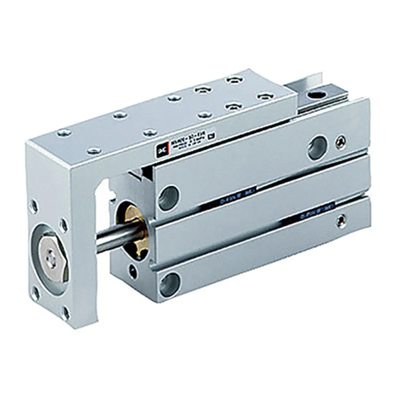
The use of an endless track linear guide produces a table cylinder
having excellent rigidity, linearity and non-rotating accuracy.
Made to Order
- XB13„: Low speed cylinder (5 to 50 mm/s)
- XC3„:
- XC19 :
- XC22 :
- XC79 :
Series
Special port location
Intermediate stroke (Spacer type)
Fluoro rubber seals
Additional machining of tapped hole, drilled hole or pinned hole
CAT.EUS20-142
Compact Slide
MXH
ø6, ø10, ø16, ø20
B
-UK
Advertisement
Table of Contents

Related Manuals for SMC Networks MXH Series

Summary of Contents for SMC Networks MXH Series
- Page 1 CAT.EUS20-142 Compact Slide Series ø6, ø10, ø16, ø20 The use of an endless track linear guide produces a table cylinder having excellent rigidity, linearity and non-rotating accuracy. Made to Order - XB13„: Low speed cylinder (5 to 50 mm/s) - XC3„: Special port location - XC19 : Intermediate stroke (Spacer type)
- Page 2 The use of an endless track linear guide having excellent rigidity, linearity, Series Series Compact Slide Improved moment tolerance Allowable moment is approximately 6 times greater than the MXU series. Long strokes up to 60 mm are now standard. Stroke (mm) Traveling 5 to 30 40 to 60...
-
Page 3: Application Example
produces a table cylinder non-rotating accuracy. ø6 ø10 ø16 ø20 A table cylinder suitable for short pitch mounting Application example Numerous variations of auto switches. Reed switches, solid state switches and 2-colour indicator type solid state switches can be mounted. ø20 bore size is now standard. -
Page 4: How To Order
Compact Slide Series ø6, ø10, ø16, ø20 How to Order Number of auto switches Compact slide 2 pcs. 1 pc. Auto switch Bore size Without auto switch 6 mm ∗ For the applicable auto switch model, 10 mm 16 mm refer to the table below. -
Page 5: Specifications
Series Compact Slide Specifications Bore size (mm) Guide rail width (mm) Fluid Action Double acting Piping port size Minimum operating pressure 0.15 MPa 0.06 MPa 0.05 MPa Maximum operating pressure 0.7 MPa Proof pressure 1.05 MPa Without auto switch: –10 to 70°C (No freezing) Ambient and fluid temperature With auto switch: –10 to 60°C (No freezing) Piston speed... - Page 6 Series Table Displacement Table Displacement due to Pitch Moment Table Displacement due to Yaw Moment Table displacement (arrow) when a load acts upon the section marked Table displacement (arrow) when a load acts upon the section marked with the arrow at the full stroke of the compact slide with the arrow at the full stroke of the compact slide MXH6 MXH6...
- Page 7 Series Compact Slide Table Displacement Table Accuracy Table Displacement due to Roll Moment Stroke (st) Traveling Table displacement (at A) when a load acts upon section F at the full 5 to 30 40 to 60 parallelism stroke of the compact slide 0.05 mm or less 0.1 mm or less Allowable moment (N·m)
-
Page 8: Model Selection
Series Model Selection Caution Confirmation of theoretical output is required separately. Refer to “Theoretical Output” on page 2. Selection Conditions : Follow the tables below in order to determine selection conditions and choose one selection graph. Vertical Horizontal l : Load eccentricity Mounting orientation Maximum speed (mm/s) Up to 100... -
Page 9: Selection Example
Series Compact Slide Selection Graph ( 4 ) to ( 12 ) (Horizontal mounting) Maximum Speed 100 mm/s or Less Maximum Speed 300 mm/s or Less Maximum Speed 500 mm/s or Less Graph ( 4 ) Load Eccentricity 50 mm Graph ( 7 ) Load Eccentricity 50 mm Graph ( 10 ) Load Eccentricity 50 mm ø20... -
Page 10: Component Parts
Brass Nickel plated Magnet holder Brass ø6 Rod seal High carbon chrome Steel ball A bearing steel Piston seal Piston gasket ø10, ø16, ø20 High carbon chrome Steel ball B bearing steel Gasket Note: The MXH series cannot be diassembled. - Page 11 Series Compact Slide Dimensions: ø6 4-M3 5 + Stroke Depth 4.8 Guide rail width 5 3-M4 through 4-M3 Plug for port (Hexagon socket head set screw) Bottom hole dia ø3.3 2-M5 Depth 5.5 4-M5 x 4 l 6-ø6 counterbore depth 3.3 4-M3 Depth 4.8 10.5...
- Page 12 Series Dimensions: ø10 4-M4 5 + Stroke Depth 6 3-M5 x 0.8 through Bottom hole dia ø4.3 6-ø7.5 counterbore depth 4.4 Guide rail width 7 4-M4 Plug for port (Hexagon socket head set screw) 2-M5 Depth 7.5 4-M5 x 4 l 4-M4 Depth 6 12.5...
- Page 13 Series Compact Slide Dimensions: ø16 4-M4 10 + Stroke Depth 6 3-M5 through Guide rail width 9 Bottom hole dia ø4.3 Plug for port (Hexagon socket head set screw) 4-M4 6-ø7.5 counterbore depth 4.4 4-M5 x 4 l Depth 10 4-M4 2-M5 Depth 6...
- Page 14 Series Dimensions: ø20 4-M5 depth 8 10 + Stroke 3-M6 through Bottom hole dia ø5.1 6-ø9.3 counterbore depth 8 Plug for port (Hexagon socket head set screw) 4-M5 4-M5 x 4 l Guide rail width 12 4-M5 depth 8 Depth 11 2-M5 15.5 52.5 + Stroke...
-
Page 15: Operating Range
Series Compact Slide Auto Switch Proper Mounting Position (Detection at stroke end) and Its Mounting Height D-A9„ D-M9„ 22 (24.5) D-F9„W ( ): denotes the values of D-A93. D-A9„V D-M9„V D-F9„WV (20) 5 (7) „ „ ( ): denotes the values of D-M9 V, D-F9 (mm) „,... -
Page 16: Tightening Torque
Series Auto Switch Mounting Watchmakers screwdriver Set screw Caution Auto Switch Mounting Tool Auto switch • When tightening the auto switch set screw (included with auto switch), use a watchmakers screwdriver with a handle 5 to 6 mm in diameter. Tightening Torque •... - Page 17 Series Auto Switch Specifications Auto Switch Common Specifications Type Reed switch Solid state switch 3-wire: 100 µA or less Leakage current None 2-wire: 0.8 mA or less Operating time 1.2 ms 1 ms or less Impact resistance 300 m/s 1000 m/s Insulation resistance 50 MΩ...
-
Page 18: Basic Wiring
Series Auto Switch Connections and Examples Basic Wiring Solid state 3-wire, NPN Solid state 3-wire, PNP 2-wire 2-wire (Solid state) (Reed switch) Brown Brown Brown Brown Load Load Indicator Load light Switch Switch Switch Black Black main main main protective circuit circuit circuit... - Page 19 Reed Switch: Direct Mounting Style D-A90(V)/D-A93(V)/D-A96(V) For details about certified products conforming to Auto Switch Specifications international standards, visit us at www.smcworld.com. PLC: Programmable Logic Controller Grommet D-A90/D-A90V (Without indicator light) Electrical entry direction: In-line D-A90/D-A90V Auto switch part no. Applicable load IC circuit, Relay, PLC Load voltage...
- Page 20 Solid State Switch: Direct Mounting Style D-M9N(V)/D-M9P(V)/D-M9B(V) For details about certified products conforming to Auto Switch Specifications international standards, visit us at www.smcworld.com. Grommet PLC: Programmable Logic Controller D-M9„/D-M9„V (With indicator light) 2-wire load current is reduced (2.5 to 40 mA) Auto switch part no.
- Page 21 2-colour Indication Solid State Switch: Direct Mounting Style D-F9NW(V)/D-F9PW(V)/D-F9BW(V) For details about certified products conforming to Auto Switch Specifications international standards, visit us at www.smcworld.com. Grommet PLC: Programmable Logic Controller D-F9„W/D-F9„WV (With indicator light) Auto switch part no. D-F9NW D-F9NWV D-F9PW D-F9PWV D-F9BW...
- Page 22 Made to Order -XB13: Low Speed Cylinder (5 to 50mm/s) Symbol Low Speed Cylinder -XB13 Even if driving at lower speeds 5 to 50mm/s, there would be no stick-slip phenomenon and it can run smoothly. How to order Standard model no. XB13 Note 1) Operate witout lubrication from a pneumatic system lubricator.
- Page 23 Series Made to Order Symbol Additional machining of tapped hole, drilled hole or pinned hole -XC79 Tapped, drilled and pinned holes can be used to mount a workpiece, etc. on the table. These will be machined according to customer requests. Standard model no.
-
Page 24: Safety Instructions
Series Safety Instructions These safety instructions are intended to prevent a hazardous situation and/or equipment damage. These instructions indicate the level of potential hazard by labels of "Caution", "Warning" or "Danger". To ensure safety, be sure to observe ISO 4414 Note 1) , JIS B 8370 Note 2) - Page 25 Series Auto Switch Precautions 1 Be sure to read this before handling. Design & Selection Warning Caution 1. Confirm the specifications. 1. Use caution when multiple actuators are used and close to each other. Read the specifications carefully and use this product appro- priately.
- Page 26 Series Auto Switch Precautions 2 Be sure to read this before handling. Mounting & Adjustment Wiring Warning Warning 1. Instruction manual 1. Confirm proper insulation of wiring. Install the products and operate them only after reading the ins- Be certain that there is no faulty wiring insulation (contact with truction manual carefully and understanding its contents.
- Page 27 Series Auto Switch Precautions 3 Be sure to read this before handling. Wiring Operating Environment Warning Caution 1. Never use in an atmosphere of explosive gases. 4. Avoid incorrect wiring. The construction of auto switches is not intended to prevent ex- <Reed switch>...
- Page 28 Series Auto Switch Precautions 4 Be sure to read this before handling. Operating Environment Caution 1. Avoid accumulation of iron debris or close contact with magnetic substances. When a large amount of ferrous debris such as machining chips or spatter is accumulated, or a magnetic substance (something attracted by a magnet) is brought into close proximity with an auto switch actuator, it may cause the auto switch (actuator) to malfunction due to a loss of the magnetic force inside the ac-...
- Page 29 Series Specific Product Precautions 1 Be sure to read this before handling. For Safety Instructions, Actuator Precautions, refer to “Precautions for Handling Pneumatic Devices” (M-03-E3A). Caution on Handling Auto Switches Operating Direction with Different Pressure Ports When installing in close proximity to each other Caution Caution 1.
- Page 30 Series Specific Product Precautions 2 Be sure to read this before handling. For Safety Instructions, Actuator Precautions, refer to “Precautions for Handling Pneumatic Devices” (M-03-E3A). Caution on Handling Auto Switches Caution 1. When tightening threads for compact slide, properly tighten within the specified torque. How to Mount a Compact Slide A compact slide can be mounted from 4 directions.
- Page 31 Series Specific Product Precautions 3 Be sure to read this before handling. For Safety Instructions, Actuator Precautions, refer to “Precautions for Handling Pneumatic Devices” (M-03-E3A). Mounting Caution 1. When tightening threads for compact slide, properly tighten within the specified torque. 2.
- Page 32 EUROPEAN SUBSIDIARIES: Spain Austria France Netherlands SMC España, S.A. SMC Pneumatik GmbH (Austria). SMC Pneumatique, S.A. SMC Pneumatics BV Zuazobidea 14, 01015 Vitoria 1, Boulevard de Strasbourg, Parc Gustave Eiffel De Ruyterkade 120, NL-1011 AB Amsterdam Girakstrasse 8, A-2100 Korneuburg Phone: +34 945-184 100, Fax: +34 945-184 124 Bussy Saint Georges F-77607 Marne La Vallee Cedex 3 Phone: +31 (0)20-5318888, Fax: +31 (0)20-5318880...
Need help?
Do you have a question about the MXH Series and is the answer not in the manual?
Questions and answers