
Related Manuals for MACH SYSTEMS 100BASE-T1


Summary of Contents for MACH SYSTEMS 100BASE-T1
- Page 1 100BASE-T1 USB Interface User Manual CHANGES Date Description Created By Review By 1.12.2020 Initial Release...
-
Page 2: Table Of Contents
100BASE-T1 USB Interface - User Manual Contents About ............................... 4 Introduction ............................. 4 Features ........................... 4 Technical Specification ........................5 Device Description ........................... 6 Overview ..........................6 Power ............................6 100BASE-T1 Connection ......................6 Pinout ............................7 4.4.1 100BASE-T1 & CAN ......................7 4.4.2... - Page 3 Table 2 100BASE-T1 & CAN Pin Assignment ................... 7 Table 3 DIP Switch Pin Assignment ......................7 Table 4 LED Function Description ......................8 Table 5 Ordering numbers for 100BASE-T1 USB Interface ..............15 List of Figures Figure 1 Block Diagram ..........................4 Figure 2 100BASE-T1 USB Interface ......................
-
Page 4: About
(Chapter 5.2). The interface offers a possibility to access SMI registers of the 100BASE-T1 transreceiver (PHY) via a CAN bus or a USB’s virtual serial port. This enables the user to evaluate signal strength, detect polarity of the T1 port, carry out a BroadR-Reach media test to diagnose cable errors, fine-tune the PHYs parameters, and generally to read and write the registers. -
Page 5: Technical Specification
100BASE-T1 USB Interface - User Manual 3 Technical Specification Electrical Ports 1x 100BASE-T1 (BroadR-Reach / OABR) 1x USB Ethernet Network Card (NIC) 1x Virtual COM Port (USB CDC) 1x CAN 2.0B (HS) Power USB-powered via Micro-USB connector (5 V DC) -
Page 6: Device Description
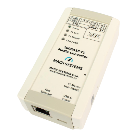
USB port. 4.3 100BASE-T1 Connection Connect 100BASE-T1 network over DSUB9M pins 4 (BP - Positive) and 5 (BM - Negative). Connect LAN over USB. Do not forget to select the select T1 Master/Slave configuration depending on your use case (Chapter 4.4.2), and to power the device (Chapter 0). -
Page 7: Pinout
DSUB 9 Male Name CAN_L T1-BP (OABR) T1-BM (OABR) D-SUB9M Front view CAN_H Table 2 100BASE-T1 & CAN Pin Assignment 4.4.2 DIP switches DIP switches Name T1 Master Master/Slave configuration User N/A; Currently unused Table 3 DIP Switch Pin Assignment Note: To change the T1 mode to Master, switch T1 Master to „ON“... -
Page 8: Can Bus Termination
5.1 USB-LAN to 100BASE-T1 Conversion Purpose of the interface is to connect a computer to 100BASE-T1 (BroadR – Reach). When the interface is plugged into a PC, it will be enumerated as a standard Ethernet network card and a virtual COM port. -
Page 9: Diagnostic Over Usb
In order to lower the power drawn from the USB port, an external power supply can be connected over DSUB connector (4.2). 100BASE-T1 mode can be changed by software (Chapter 5.2) or by hardware (set DIP switches to position „ON“ for User mode „Master“). -
Page 10: Figure 9 Serial Com Port
100BASE-T1 USB Interface - User Manual Figure 9 Serial COM port Figure 10 Main Screen of the utility (1), COM port number of the device (2) Device’s serial number (3) T1 signal quality (4) current T1 mode (5) T1 link status... -
Page 11: Firmware Update
100BASE-T1 USB Interface - User Manual Note: Mode of the Media Converter can be changed by software (11) or by hardware (set DIP switch T1 Master to position „ON“ for User mode „Master“). 6 Firmware Update For updating the device’s firmware, you will need a .MSF firmware file, MsFirmwareUpdater application, and a Micro-USB cable. -
Page 12: Updating Process
100BASE-T1 USB Interface - User Manual Note: After you open the app, check the COM port number. Default number is valid only for the connecting app to the device, but not for the updating firmware itself. 6.2 Updating Process Steps: 1. -
Page 13: Legal Information
CORRECTION OF DEFECTS, AND MACH SYSTEMS s.r.o. HEREBY EXPRESSLY DISCLAIMS ANY LIABILITY OVER AND ABOVE THE REFUNDING OF THE PRICE PAID FOR THIS DEVICE, SINCE MACH SYSTEMS s.r.o. DOES NOT HAVE ANY INFLUENCE ON THE IMPLEMENTATIONS OF THE HIGHER-LEVEL SYSTEM, WHICH MAY BE DEFECTIVE. -
Page 14: Declaration Of Conformity
100BASE-T1 USB Interface - User Manual 7.3 Declaration of Conformity MACH SYSTEMS s.r.o. Page 14 of 15 www.machsystems.cz info@machsystems.cz... -
Page 15: Patents, Copyrights And Trademarks
8 Ordering Information Product Number Description 100BASET1-USB-IF 100BASE-T1 USB Interface DIN-CLIP Clip for mounting on a DIN rail Table 5 Ordering numbers for 100BASE-T1 USB Interface 9 Contact MACH SYSTEMS s.r.o. www.machsystems.cz info@machsystems.cz Czech Republic Company registration: 29413893 EU VAT number: CZ29413893 MACH SYSTEMS s.r.o.
Need help?
Do you have a question about the 100BASE-T1 and is the answer not in the manual?
Questions and answers