PAW SolarBloC midi 2D Installation And Commissioning Instructions
Dn 20
Hide thumbs
Also See for SolarBloC midi 2D:
- Installation and commissioning instructions (32 pages) ,
- Installation and operation instruction manual (40 pages)
Table of Contents
Advertisement
Quick Links
Advertisement
Table of Contents

Subscribe to Our Youtube Channel
Related Manuals for PAW SolarBloC midi 2D


Summary of Contents for PAW SolarBloC midi 2D
- Page 1 PAW GmbH & Co. KG Böcklerstr. 11, D-31789 Hameln, Germany Phone: +49-5151-9856-0, Fax: +49-5151-9856-98 E-mail: info@paw.eu, Web: www.paw.eu Installation and Commissioning Instructions SolarBloC midi 2D – DN 20 2016/05 997655910x-mub-en – V07...
- Page 2 Translation of the original instructions PAW GmbH & Co. KG We reserve the right to make technical changes without notice! Böcklerstraße 11 Printed in Germany – Copyright by PAW GmbH & Co. KG D-31789 Hameln, Germany 997655910x-mub-en – V07 2016/05...
-
Page 3: Table Of Contents
1 General Information Contents General Information ......................4 About these instructions ....................4 About this product ......................4 Designated use ......................5 Safety instructions ......................6 Assembly and installation [specialist] ................8 Commissioning [specialist] ..................... 11 Flushing and filling the solar circuit ................12 Preparations before flushing .................. -
Page 4: General Information
About these instructions These instructions describe the installation, commissioning, function and operation of the 3-line solar stations SolarBloC midi 2D (DN 20) for installations with 2 roofs. The chapters called [specialist] are intended for specialists only. For other components of the solar installation, such as collectors, storage tanks, expansion tanks and controllers, please observe the instructions of the corresponding manufacturer. -
Page 5: Designated Use
Due to its design, the station must be mounted and operated as described in these instructions! Improper usage excludes any liability claims. Only use PAW accessories with the solar station. Under the influence of solar radiation, the collectors can get very hot. -
Page 6: Safety Instructions
2 Safety instructions 2 Safety instructions The installation and commissioning as well as the connection of electrical components require technical knowledge commensurate with a recognised vocational qualification as a fitter for plumbing, heating and air conditioning technology, or a profession requiring a comparable level of knowledge [specialist]. - Page 7 2 Safety instructions CAUTION Personal injury and damage to property due to overpressure! By closing the two ball valves in the primary circuit, the safety group is separated from the heat exchanger. A rise in temperature in the storage tank will cause high pressures which can result in personal injury or damage to property! ...
-
Page 8: Assembly And Installation [Specialist]
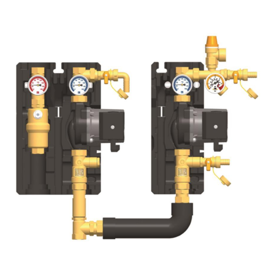
3 Assembly and installation [specialist] 3 Assembly and installation [specialist] NOTICE Material damage due to high temperatures! As the solar fluid can be very hot near the collector, the group of fittings must be installed at a sufficient distance from the collector field. It may be necessary to install an intermediate tank to protect the expansion tank. - Page 9 3 Assembly and installation [specialist] 1. Remove the station from the packaging. 2. Take off the insulating front shells. 3. Screw the connecting piece [6] onto the return connections of the 2-line station and the 1-line station (see figure). 4. Copy the mounting holes of the solar station besides the thermometers to the mounting surface.
- Page 10 3 Assembly and installation [specialist] 7. Connect the pipe for the expansion tank below the pressure gauge [7.5] and fix the bracket for the expansion tank. 8. Adapt the initial pressure of the expansion tank to the installation and connect the expansion tank.
-
Page 11: Commissioning [Specialist]
4 Commissioning [specialist] 4 Commissioning [specialist] Please observe the following safety instructions regarding the commissioning of the station: WARNING Risk of burning and scalding! The valves and fittings can heat up to more than 100 °C. It is therefore not allowed to flush or fill the installation when the collectors are hot (intense solar radiation). -
Page 12: Flushing And Filling The Solar Circuit
4 Commissioning [specialist] Flushing and filling the solar circuit The fill and drain valves necessary to flush and fill the installation are integrated in the solar station. To flush dirt particles out of the installation, only use flush and fill stations with fine filters. Ball valve with integrated check valve (Normal flow direction in the figure: downwards) 0°... - Page 13 4 Commissioning [specialist] Airstop The Airstop with manual vent valve is used to vent the solar system. To ensure a perfect venting of the solar circuit, the flow velocity in the flow line must be at least 0.3 m/s. Pipe diameter [mm] Flow rate at 0.3 m/s ∅...
-
Page 14: Preparations Before Flushing
4 Commissioning [specialist] Preparations before flushing The solar circuit is flushed in the direction of flow. 1. Disconnect the expansion tank from the solar installation. Please observe the separate instructions regarding the expansion tank! 2. Close the return ball valves [1.2ᅵ7.2] (90°, see page 12). 3. -
Page 15: Flushing And Filling
4 Commissioning [specialist] Flushing and filling 1. Open the fill and drain valves [7.4|9.2]. 2. Put the flush and fill station into operation and flush the installation until clear solar fluid exits. Vent the solar installation several times at the vent plug of the Airstop [4.2] until the solar fluid exits without bubbles (see page 13). - Page 16 4 Commissioning [specialist] 9. Close the drain valve [9.2] while the filling pump is running and increase the system pressure to about 5 bars. The system pressure is displayed on the pressure gauge. 10. Check the pressure gauge to see if the system pressure decreases and eliminate leaks if necessary.
- Page 17 4 Commissioning [specialist] WARNING Risk to life and limb due to electric shock! Check if the sensors and pumps are properly connected to the controller and if the controller housing is closed. Only then, the mains plug of the controller can be plugged into a socket. 15.
-
Page 18: Adjustment Of The Solar Installation
4 Commissioning [specialist] Adjustment of the solar installation 1. Set the desired revolution speed of the solar pump depending on the required flow rate. If necessary, the flow rate can be reduced by the ball valve [3.1] (only necessary if the pump is not speed-controlled). -
Page 19: Maintenance [Specialist]
5 Maintenance [specialist] 5 Maintenance [specialist] Draining the solar installation 1. Switch off the controller and make sure that a restart is not possible. 2. Open the check valves in the return ball valves [1.2I7.2], by turning them to position 45°... -
Page 20: Spare Parts [Specialist]
6 Spare parts [specialist] 6 Spare parts [specialist] NOTICE Complaints and requests/orders of spare parts will only be processed with information on the serial number! The serial number is placed on the safety group of the solar station. In case of a complaint, please send us the entirely completed commissioning report on page 26. - Page 21 6 Spare parts [specialist] Pump Item number Wilo-Yonos PARA ST 15/7.0 E123207MO Wilo-Yonos PARA ST 15/13 E12320135 Grundfos UPM3 Solar 15-75 E121617 Grundfos UPM3 Solar 15-145 E121620 Connection of the PWM pumps Wilo-Yonos PARA ST 15/7.0 Wilo-Yonos PARA ST 15/13 Grundfos UPM3 Solar 15-75 Grundfos UPM3 Solar 15-145 brown...
-
Page 22: Technical Data
7 Technical data 7 Technical data Dimensions Total height 493 mm Total width 584 mm Depth 152 mm Centre distance, flow / return 100 mm Centre distance, return / return 250 mm Pipe connections ¾" internal thread Connection for expansion tank ¾"... - Page 23 7 Technical data 2016/05 997655910x-mub-en – V07...
-
Page 24: Function Of The Check Valves [Expert]
8 Function of the check valves [Expert] 8 Function of the check valves [Expert] Within their application range, the check valves of this station prevent unwanted gravity circulation. The functioning of the check valves depends on: the installation height the temperature difference between the storage tank and the collector ... - Page 25 8 Function of the check valves [Expert] Do you wish to get further information? The density of the solar fluid decreases with rising temperature. In high installations with large temperature differences, the difference in density will cause gravity circulation. This circulation can lead to a cooling down of the storage tank.
-
Page 26: Commissioning Report
9 Commissioning report 9 Commissioning report Installation operator Location of installation Collectors (number / type) Collector surface m² (Height difference between Installation height station and collector field) Piping ⌀ Venting ⃞ Manual vent valve ⃞ Automatic vent valve (collector field) ⃞... - Page 27 9 Commissioning report 2016/05 997655910x-mub-en – V07...
- Page 28 PAW GmbH & Co. KG www.paw.eu Böcklerstraße 11 Phone: +49 (0)5151 9856 - 0 D-31789 Hameln, Germany Telefax: +49 (0) 5151 9856 - 98 997655910x-mub-en – V07 2016/05...
Need help?
Do you have a question about the SolarBloC midi 2D and is the answer not in the manual?
Questions and answers