Table of Contents
Advertisement
Quick Links
Advertisement
Table of Contents

Related Manuals for Cascade Sciences CVO-5


Summary of Contents for Cascade Sciences CVO-5
- Page 1 Vacuum Purge Ovens CVO-5 CVO-5-2 CVO-10 Installation - Operation Manual...
- Page 2 Part Number (Manual): 4861790 Revision: August 23, 2018 The CVO-5 requires a standard 110 – 120-volt power supply outlet to plug into (NEMA 5-15). The CVO5-2 and CVO-10 require a 220 – 240-volt power supply outlet to plug into (NEMA 6-15R).
-
Page 3: Table Of Contents
TABLE OF CONTENTS CERTIFICATIONS ..............................5 UNIT SPECIFICATIONS ............................. 7 Temperature .................................... 7 Power ......................................7 Weight ......................................8 Dimensions ....................................8 Capacity ....................................9 Shelf Capacity by Weight ..............................9 INTRODUCTION ................................11 Read this Manual ................................... 11 Contacting Assistance ................................. 11 Engineering Improvements.............................. - Page 4 REPLACEMENT PARTS ............................53 P a g e cascadesciences.com Tel. 503 847-9047...
-
Page 5: Certifications
CERTIFICATIONS This certificate satisfies NRTL safety requirements TÜV SÜD CUE Certificate Number: U8 17 04 64872 077 These units are CUE listed by TÜV SÜD as vacuum ovens for appropriate professional, industrial, or educational use. TÜV SÜD America Inc. is an OSHA recognized NRTL and a Standards Council of Canada accredited certification body. - Page 6 CERTIFICATIONS P a g e cascadesciences.com Tel. 503 847-9047...
-
Page 7: Unit Specifications
All indications are average values, typical for units produced in the series. We reserve the right to alter technical specifications at all times EMPERATURE Model Range Uniformity Stability CVO-5 ± 0.4° @105°F Ambient +26° to 250°F +1.5° @ 105°F CVO-5-2 Ambient +26° to 250°F +1.5° @ 105°F ±... -
Page 8: Weight
UNIT SPECIFICATIONS EIGHT Model Shipping Net Weight CVO-5 449 lb / 203. 7kg 360 lb / 163.3 kg CVO-5-2 449 lb / 203.7 kg 360 lb / 163.3 kg CVO-10 775 lb / 352 kg 663 lb / 301 kg... -
Page 9: Capacity
UNIT SPECIFICATIONS APACITY Model Cubic Feet Liters CVO-5 127.4 CVO-5-2 127.4 CVO-10 264.0 HELF APACITY BY EIGHT Model Per Shelf Total CVO-5 50.0 lb / 22.6 kg 225.0 lb / 102.0 kg CVO-5-2 50.0 lb / 22.6 kg 225.0 lb / 102.0 kg CVO-10 50.0 lb / 22.6 kg... - Page 10 UNIT SPECIFICATIONS 10 | P a g e cascadesciences.com Tel. 503 847-9047...
-
Page 11: Introduction
NGINEERING MPROVEMENTS Cascade Sciences continually improves all of its products. As a result, engineering changes and improvements are made from time to time. Therefore, some changes, modifications, and improvements may not be covered in this manual. If your unit’s operating characteristics or appearance differs from those described in this manual, please contact your oven dealer or customer service representative for assistance. -
Page 12: Vacuum Supply Required
ACUUM UPPLY EQUIRED Vacuum Pump CVO ovens require a vacuum supply source, which must be purchased separately from the oven. Please see the Cascade Sciences website for pumps and vacuum system accessories suitable for your application. cascadesciences.com/vacuum-pumps Building Vacuum Supply... -
Page 13: Receiving Your Oven
RECEIVING YOUR OVEN NSPECT THE HIPMENT When an oven leaves the factory, safe delivery becomes the responsibility of the carrier. • Damage sustained during transit is not covered by the manufacturing defect warranty. • Save the shipping carton until you are certain that the unit and its accessories function •... -
Page 14: Orientation
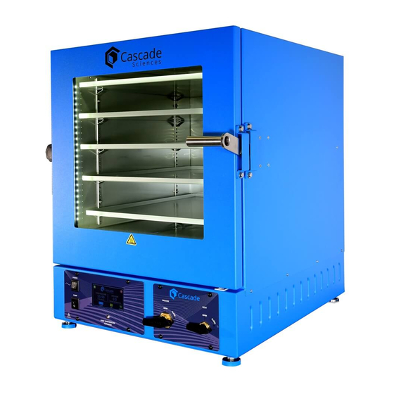
RECEIVING YOUR OVEN RIENTATION CVO-10 Chamber Door Latch Door Seal, Oven Chamber Door Intake Vent Control (controls backfilling of external Control Panel atmosphere into the oven chamber) Temperature Probe KF-25 Vacuum Port for sensor probes KF-25 Vacuum Port – connects to the vacuum pump. - Page 15 RECEIVING YOUR OVEN CVO-5s Chamber Door Latch Intake Vent Control (controls backfilling of external atmosphere into the oven chamber) Control Panel Vacuum Outlet Valve Control KF-25 Vacuum Por Intake Vent Port ¼ inch Vacuum Port 3/8-inch OD Vacuum Pump Power Outlet Power Cord Inlet 15 | P a g e...
- Page 16 NEMA 6-20R CVO-5s Fuse holder(s) for the power outlet: Fuse Holder – CVO-5-2 only Vacuum Port – 3/8” OD CVO-5 1 Fuse, CVO5-Xs 2 Fuses Chamber Intake Vent ¼” OD USB Data Port Power outlet for vacuum pumps. Power Cord...
-
Page 17: Record The Data Plate Information
RECEIVING YOUR OVEN ECORD THE LATE NFORMATION The data plate contains the unit model number and serial number. Tech Support will need this information during any support call. Record it below for future reference. • The data plate is located on the lower left side of the oven near the back. Model Number: Serial Number: 17 |... - Page 18 RECEIVING YOUR OVEN 18 | P a g e cascadesciences.com Tel. 503 847-9047...
-
Page 19: Installation
INSTALLATION NSTALLATION ROCEDURE HECKLIST For installing the oven in a new workspace location. Pre-Installation Verify a vacuum supply source suitable for your application is available and can be connected to the oven, page Error! Bookmark not defined.. See page 25 for the oven gas and vacuum port locations. •... -
Page 20: Required Ambient Conditions
INSTALLATION EQUIRED MBIENT ONDITIONS These units are built for use indoors at room temperatures between 15°C and 40°C (59°F and 104°F), at no greater than 80% Relative Humidity (at 25°C / 77°F). Operating outside these conditions may adversely affect the unit temperature performance. When selecting a location to install the unit, consider all environmental conditions that can impact its temperature performance. -
Page 21: Power Source Requirements
The recommended wall circuit breaker for these units are: • CVO-5: 15 amps CVO-5-2, CVO-10: 15 amps A separate circuit for the oven is recommended to prevent possible loss of product due to • overloading or failure of other equipment on the same circuit. -
Page 22: General Power Safety
INSTALLATION Accessory Outlet Fuses: Each oven ships with one or more 5x20mm fuses installed fuse holders next to the accessory outlet. Model Type Quantity Max allowed outlet draw CVO-5 T8A 250V 8 amps CVO-5-2 T4A 250V 4 amps CVO-10 T4A 250V 4 amps These fuses do not protect against overcurrent conditions in the major systems of the oven. -
Page 23: Leveling
INSTALLATION EVELING Install the 4 leveling feet in the 4 corner holes in the bottom of the oven. The oven must be level and stable for safe operation. To prevent damage when moving the unit, turn all four leveling feet so that the leg of each Note: foot sits inside the unit. -
Page 24: Shelving Installation
INSTALLATION HELVING NSTALLATION CVO-5s To ensure accurate temperature measurement, one shelf bottom must be in close proximity to the oven temperature probe. This probe extends out from the chamber back wall. Do not place the shelf in direct contact with the probe. Install the shelves evenly spaced in the oven chamber to maximize temperature uniformity. -
Page 25: Connect To The Vacuum Supply
INSTALLATION ONNECT TO THE ACUUM UPPLY KF-25 CVO-10 Connect your vacuum supply to this KF-25 port. Connection Kit Pump Vacuum Connection Optional: Connect the vacuum pump to the accessory power outlet on the back of the oven. Pump Power Supply 4 amps is the maximum allowed power draw for the accessory outlet on all CVO-10 ovens. - Page 26 Pump Power Supply 8 amps is the maximum allowed power draw for CVO-5 accessory outlet. 4 amps is the maximum allowed power draw for CVO-5-2 accessory outlet. 26 | P a g e cascadesciences.com...
-
Page 27: Connect To A Gas Backfill Supply
INSTALLATION Exceeding 15 psi of gas backfill pressure may damage the oven. ONNECT TO A ACKFILL UPPLY Optional: A clean or inert gas supply—such as nitrogen (N ) or argon—may be connected to the vent intake port located on the back of the oven. This supply will backfill the evacuated oven chamber when the vent intake valve is opened on the front control panel. - Page 28 INSTALLATION 28 | P a g e cascadesciences.com Tel. 503 847-9047...
-
Page 29: Graphic Symbols
GRAPHIC SYMBOLS The oven is provided with multiple graphic symbols on its interior and exterior surfaces and display screen. The symbols identify hazards and the functions of the adjustable components as well as important notes in the user manual. Symbol Definition Consult the user manual Consulter le manuel d'utilisation... - Page 30 GRAPHIC SYMBOLS 30 | P a g e cascadesciences.com Tel. 503 847-9047...
-
Page 31: Control Overview
CONTROL OVERVIEW Control Panel Power Switch Controls all power the oven and its systems. Pump Switch This switch supplies power to the vacuum pump power outlet on the back of the oven. Over Temperature Activated This red light illuminates when the Over Temperature heating cutoff system routes power away from the heating elements. - Page 32 CONTROL OVERVIEW Home Screen Icons and Controls Setpoint Button This blue button shows the current setpoint. The setpoint is the temperature the oven heats to once the Heat Button is pushed (see below). Pressing the Setpoint Button brings up the setpoint page and the keypad used to enter a new setpoint.
- Page 33 CONTROL OVERVIEW Home Screen Icons and Controls (Continued) Standby The red off-style button on homepage places the display in a standby mode. Menu Screen Home Button The home button returns a menu screen to the homepage CVO-10 Valves Vacuum Valve Vent Valve Vacuum Valve Control The Vacuum Control is located on the left side of the oven on a KF-25 vacuum port.
- Page 34 CONTROL OVERVIEW CVO-5 Valves Vacuum Valve Control This valve adjusts the level of vacuum draw applied to the oven chamber through the vacuum port on the back of the oven. When open, this valve allows the connected vacuum supply to evacuate the oven •...
-
Page 35: Operation
OPERATION Safe operation of the oven is dependent on the actions and behavior of the oven operators. Operating personnel must read and understand the Safety Guidelines and Operating Precautions in this section prior to operating the oven. The operators must follow these instructions to prevent injuries and to safeguard their health, environment, and the materials being treated in the oven, as well as to prevent damage to the oven. -
Page 36: Operating Precautions
OPERATION Warning Hot Surfaces: These areas are marked with Hot Surface labels. Proper protective equipment should be employed to minimize the risk of burns. Avertissement Surface Chaude: Ces zones sont marquées avec des étiquettes de surface chaude. Un équipement de protection approprié devrait être utilisé pour minimiser le risque de brûlures. PERATING RECAUTIONS Do not use this oven in unsafe improper applications that produce flammable or combustible... -
Page 37: Theory Of Operation
OPERATION HEORY OF PERATION Vacuum Vacuum is supplied by an external vacuum supply (a pump or building system) connected to one of the oven vacuum ports. Vacuum levels obtained in the oven chamber are dependent on pump type and performance, valve settings, and the nature of the application or process, including the volume of materials outgassed. - Page 38 OPERATION Heating Control The oven temperature controller stores an operator-selected constant temperature setpoint. When powered, the oven heats the chamber shelves to the setpoint. The controller board is wired to a solid-state temperature probe located in the chamber on the rear wall. When the controller detects that the shelf temperature has dropped below the temperature setpoint, it pulses power to the heating elements.
-
Page 39: Put The Oven Into Operation
OPERATION There may be light smoking from protective oil coatings on the elements when running the Note: oven near its maximum temperature for the first time. UT THE VEN INTO PERATION Verify all required procedures in the Installation chapter have been completed before beginning. Plug In the Power Cord Attach the power cord that came with the unit to the power inlet receptacle on the back of the oven. -
Page 40: Evacuating And Backfilling The Oven Chamber
OPERATION VACUATING AND ACKFILLING THE HAMBER Put the oven chamber under vacuum for at least 10 minutes when first putting the oven into operation in a new location to verify the integrity of the vacuum supply system. Reminder: The oven must be plumbed to a vacuum supply source before starting this procedure. Evacuate the Oven Chamber Verify the Vacuum and Vent Valve controls are in the closed position This protects your vacuum pump from exposure to streaming... -
Page 41: Set The Temperature Setpoint
OPERATION Note: The oven temperature probe must be in close proximity to a shelf to obtain an accurate display reading. See page 24. ET THE EMPERATURE ETPOINT Enter and save the target temperature of your baking application. Begin on the homepage Jump to the temperature setpoint menu. -
Page 42: Heat The Oven
OPERATION EAT THE After saving a setpoint, the oven is ready to begin heating. To heat the oven: Press the green Play button. The play button will be replaced by a red Pause button. • The Heat icon on the lower left side of the display will blink on and off as the oven •... -
Page 43: Flashing Temperature
OPERATION LASHING EMPERATURE The displayed temperature begins flashing when the chamber pressure rises by 3inHg or more or when the chamber door is opened. This indicates the display is showing the last measured vacuum temperature of the chamber shelving and not the current air temperature of the backfilled chamber. There can be a difference of up to +3°F temperature between the air and shelving temperatures during the first minutes after the chamber has backfilled. -
Page 44: Changing The Oven Settings
OPERATION HANGING THE ETTINGS Starting on the homepage, press the green Settings Button. The display will jump to the settings menu. • 2. Use the slider bars on the settings page to change the units of measurement and screen brightness as needed. The settings menu controls: Temperature units of measurements –... -
Page 45: User Maintenance
USER MAINTENANCE Warning: Prior to any maintenance or cleaning of this unit, disconnect the power cord from the power supply. Avertissement: Avant d'effectuer toute maintenance ou entretien de cet appareil, débrancher le cordon secteur de la source d'alimentation. LEANING AND ISINFECTING If a hazardous material or substance has spilled in the oven, immediately initiate your site Hazardous Material Spill Containment protocol. -
Page 46: Maintaining Atmospheric Integrity
USER MAINTENANCE Disinfecting Disinfect the oven if algae, mold, bacteria, or other biological contaminants are an issue. For maximum effectiveness, disinfection procedures are typically performed after cleaning. Keep the following points in mind: Turn off and unplug the unit to safeguard against electrical hazards. •... -
Page 47: Vacuum Pump Maintenance
USER MAINTENANCE ACUUM AINTENANCE Vacuum pumps are high wear equipment and require replacement of seals and diaphragms at least once per year. Poor vacuum performance or bubbling or strained noises from the pump may indicate that the pump is in need of maintenance. Pump Manuals Refer to the operation manual supplied with your vacuum pump for recommended maintenance routines such as oil levels, replacement of sorbent charge, and exhaust filter change outs. -
Page 48: Calibrate The Temperature Display
The device must be accurate to at least 0.1°F and should be regularly calibrated by a third party. Never use alcohol or mercury-based thermometers! Cascade Sciences CVO ovens do not normally require calibration. Should your SOP or quality program require calibrations, follow this guideline. - Page 49 USER MAINTENANCE 5. Heat up and stabilization period: The oven temperature must be stable at temperature and under vacuum in order to perform an accurate calibration. The temperature is considered stabilized when the oven chamber has operated at your • calibration temperature for at least 30 minutes with no fluctuations greater than ±0.4°F.
- Page 50 USER MAINTENANCE Calibration continued jump to the temperature setpoint menu a. Press the blue setpoint button on the display screen homepage. The temperature setpoint The display will jump to the temperature Setpoint • menu setpoint page. Place the setpoint page into its calibration mode. a.
- Page 51 USER MAINTENANCE Calibration continued Wait 30 minutes for the oven to stabilize after the oven has achieved the setpoint with the corrected display adjustment. Failure to wait will result in an inaccurate oven • display reading. Once the temperature has stabilized, compare the reference Reference Device device and the oven display temperature reading again.
- Page 52 USER MAINTENANCE 52 | P a g e cascadesciences.com Tel. 503 847-9047...
- Page 53 Please see the 3300546 CVO-5 illustration on page 16. Fuse, accessory power outlet for the CVO-5-2 and CVO-10 5x20mm, 4 Amp, 250V. 2 fuses are required to operate the accessory power outlet. These...
- Page 54 REPLACEMENT PARTS Description Parts Number Shelf clips for CVO-5 and CVO-5-2 ovens Requires 4 clips per shelf 1250510 Power cord, CVO-5 125 volt, 15Amp, 9ft 5 in (2.86m), NEMA 5-15P 1800510 Power cord, CVO-5-2 and CVO-10 250 Volt, 13Amp, 8.2 feet (2.5m), NEMA 6-15P...
- Page 55 REPLACEMENT PARTS 55 | P a g e cascadesciences.com Tel. 503 847-9047...
Need help?
Do you have a question about the CVO-5 and is the answer not in the manual?
Questions and answers