Table of Contents
Advertisement
Quick Links
Advertisement
Table of Contents

Subscribe to Our Youtube Channel
Related Manuals for Cascade Sciences CVO-2


Summary of Contents for Cascade Sciences CVO-2
- Page 1 Benchtop Vacuum Ovens CVO-2 Installation - Operation Manual...
- Page 2 The CVO-2 requires a standard 110 – 120-volt power supply outlet to plug into (NEMA 5-15R). Warning: This product contains chemicals, including Triglycidyl Isocyanurate, known to the State of California to cause cancer as well as birth defects or other reproductive harm. For more information go to www.P65Warnings.ca.gov.
- Page 3 Benchtop Vacuum Ovens 110 – 120 Voltage Part Number (Manual): 4861832 Revision: July 15, 2019 P a g e cascadesciences.com Tel. 503 847-9047...
-
Page 4: Table Of Contents
TABLE OF CONTENTS CERTIFICATIONS ............................... 7 UNIT SPECIFICATIONS ............................9 Temperature Performance ..............................9 Power ....................................... 10 Vacuum ....................................10 Weight ...................................... 10 Dimensions ..................................... 10 Capacity ....................................10 Shelf Capacity by Weight ..............................11 INTRODUCTION ............................... 13 Read this Manual .................................. 13 Contacting Assistance ................................ - Page 5 Electrical Components ............................... 49 Vacuum Pump Maintenance ............................49 REPLACEMENT PARTS LIST........................... 51 P a g e cascadesciences.com Tel. 503 847-9047...
- Page 6 TABLE OF CONTENTS P a g e cascadesciences.com Tel. 503 847-9047...
-
Page 7: Certifications
CERTIFICATIONS This certificate satisfies NRTL safety requirements TÜV SÜD CUE Certificate Number: U8 064872 0095 These units are CUE listed by TÜV SÜD as vacuum ovens for appropriate professional, industrial, or educational use. TÜV SÜD America Inc. is an OSHA recognized NRTL and a Standards Council of Canada accredited certification body. - Page 8 CERTIFICATIONS P a g e cascadesciences.com Tel. 503 847-9047...
-
Page 9: Unit Specifications
UNIT SPECIFICATIONS Please refer to the oven data plate for individual electrical specifications. Technical data specified applies to units with standard equipment at an ambient temperature of 25°C ±3° (77°F ±5.4°) and at nominal voltage. The temperatures specified are determined in accordance with factory standards respecting the recommended wall clearances of 10% of the height, width, and depth of the inner chamber. -
Page 10: Power
SPECIFICATIONS OWER AC Voltage Amperage Frequency 110 – 120 50/60 Hz ACUUM Operational Vacuum Range inHg mmHg -3.0 to -29.9 -76 to -760 -10 to -101 -0.1016 to -1.0125 Vacuum Display Range inHg mmHg 0.0 to -29.9 37.5 to - 757 5 to -101 0.05 to -1.013 EIGHT... -
Page 11: Shelf Capacity By Weight
SPECIFICATIONS HELF APACITY BY EIGHT Per Shelf Total 35.0 lb / 15.8 kg 105.0 lb / 47.6 kg 11 | P a g e cascadesciences.com Tel. 503 847-9047... - Page 12 SPECIFICATIONS 12 | P a g e cascadesciences.com Tel. 503 847-9047...
-
Page 13: Introduction
NGINEERING MPROVEMENTS Cascade Sciences continually improves all of its products. As a result, engineering changes and improvements are made from time to time. Therefore, some changes, modifications, and improvements may not be covered in this manual. If your unit’s operating characteristics or appearance differs from those described in this manual, please contact your oven dealer or customer service representative for assistance. -
Page 14: Vacuum Supply Required
INTRODUCTION ACUUM UPPLY EQUIRED CVO ovens require a vacuum supply source, which must be purchased separately from the oven. Please see the Cascade Sciences website for pumps and vacuum system accessories suitable for your application. Vacuum Pump cascadesciences.com/vacuum-pumps Building Vacuum Supply... -
Page 15: Receiving Your Oven
6. Verify that the correct number of accessories has been included. Carefully check all packaging for loose accessory items before discarding. Included Accessory Items Tall Shelves Medium Shelves Short Shelf w/ Clip Power Cord, Leveling Feet CVO-2 15 | P a g e cascadesciences.com Tel. 503 847-9047... -
Page 16: Orientation
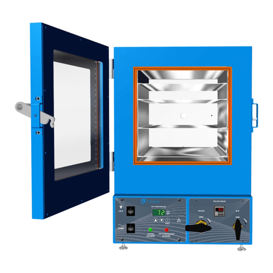
RECEIVING RIENTATION Front CVO-2 Chamber Liner Gasket (color varies) Temperature Sensor Probe Control Panel Vacuum Valve Intake Vent Control (allows external Control atmosphere into the oven chamber) 16 | P a g e cascadesciences.com Tel. 503 847-9047... - Page 17 RECEIVING Back KF-25 Vacuum Port Intake Vent Port ¼ inch OD Vacuum Port 3/8 inch OD Power Cord Inlet 17 | P a g e cascadesciences.com Tel. 503 847-9047...
- Page 18 RECEIVING Power Panels Located on the back of each unit. CVO-2 Backfilling Intake Vent for the Vacuum Inlet 3/8in (9.52mm) OD – oven chamber, ¼ in (6.35mm) OD Connects to the vacuum pump or supply Data Plate Power Cord Inlet with fuse...
-
Page 19: Recording The Data Plate Information
RECEIVING ECORDING THE LATE NFORMATION Record the unit model number and serial number below for future reference. Tech Support needs this information to provide accurate help during support calls and emails. • The data plate is located on the lower left side of the oven, above the power cord inlet. Data Plate Information MODEL NO: SERIAL NO:... - Page 20 RECEIVING 20 | P a g e cascadesciences.com Tel. 503 847-9047...
-
Page 21: Installation
INSTALLATION NSTALLATION ROCEDURE HECKLIST For installing the oven in a new workspace location. Pre-Installation Verify a vacuum supply source suitable for your application is available and can be connected to the oven, page 14. See page 28 for the oven gas and vacuum port locations. •... -
Page 22: Required Ambient Conditions
INSTALLATION EQUIRED MBIENT ONDITIONS These units are built for use indoors at room temperatures between 15°C and 40°C (59°F and 104°F), at no greater than 80% Relative Humidity (at 25°C / 77°F). Operating outside these conditions may adversely affect the unit temperature performance. When selecting a location to install the unit, consider all environmental conditions that can impact its temperature performance. -
Page 23: Power Source Requirements
Power Cords The unit must be positioned so that all operators can quickly unplug the power cord in the event of an emergency. The CVO-2 is provided with a 125V, 15A, 9ft 5in (2.86m), NEMA 5-15P power cord. • •... -
Page 24: General Power Safety
CVO ovens ship with the following 5x20mm fuses installed: Model Type Quantity Location CVO-2 Power cord inlet. T8A 250V ENERAL OWER AFETY Your unit and its recommended accessories are designed and tested to meet strict safety requirements. -
Page 25: Lifting And Handling
INSTALLATION IFTING AND ANDLING The oven is heavy. Use appropriate lifting devices that are sufficiently rated for these loads. Follow these guidelines when lifting the oven: Lift the oven only from its bottom surface. • Doors, handles, and knobs are not adequate for lifting or stabilization. •... -
Page 26: Install The Oven
INSTALLATION NSTALL THE Place the unit in a workspace location that meets the criteria discussed in the previous entries of the Installation section. Verify the oven stands level and does not rock. Adjust the leveling feet or casters as • needed. -
Page 27: Shelving Installation
2. Place the 2 tall shelves on top of the short shelf. 3. Place the 2 medium shelves on top of the tall shelves. CVO-2 Shelving Configuration Temperature Probe 27 | P a g e cascadesciences.com... -
Page 28: Connect To The Vacuum Supply
INSTALLATION ONNECT TO THE ACUUM UPPLY KF-25 Vacuum Flange Vacuum Port 3/8 inch (9.52mm) Vacuum Connections Vacuum Line Connected to the Vacuum Port Use of clamps to secure tubing to the Vacuum Port and Chamber Vent is recommended. • The Vacuum Port – 3/8 inch (9.52mm) OD Connect a vacuum pump or building vacuum supply system to this port. -
Page 29: Connect To A Gas Backfill Supply
The maximum allowed gas backfill pressure is 15 psi. Exceeding 15 psi of gas backfill pressure may damage the oven. Intake Vent – To the oven CVO-2 chamber ¼ in (6.35mm) OD Gas Supply Intake Vent 29 | P a g e cascadesciences.com... - Page 30 INSTALLATION 30 | P a g e cascadesciences.com Tel. 503 847-9047...
-
Page 31: Graphic Symbols
GRAPHIC SYMBOLS The oven is provided with graphic symbols on its exterior. These identify hazards and adjustable components, as well as important notes in the user manual. Symbol Definition Consult the user manual. Consulter le manuel d'utilisation AC Power Repère le courant alternatif I/ON O/OFF I indique que l'interrupteur est en position marche. - Page 32 SYMBOLS 32 | P a g e cascadesciences.com Tel. 503 847-9047...
-
Page 33: Control Overview
CONTROL OVERVIEW Light Switch Controls the oven chamber light. Power Switch Controls all power to the oven and its systems. Set Temperature Display and Controls Shows the current chamber temperature. The Up and Down arrow buttons are used to access the Temperature Set Point (SP) or Calibration Offset (C O) display modes and input the temperature set point or calibration adjustment value. - Page 34 CONTROL Vacuum Gauge This gauge is set at the factory to show the chamber vacuum level relative to sea level atmospheric pressure in inches of mercury (inHg). The display range is 0 to -29.9inHg. Zero is the room atmosphere pressure at sea level and -29.9inHg a near-perfect vacuum. See page 44 for how to display other units of measurement or zero the gauge to your local altitude.
-
Page 35: Operation
OPERATION Safe operation of the oven is dependent on the actions and behavior of the oven operators. Operating personnel must read and understand the Safety Guidelines and Operating Precautions in this section prior to operating the oven. The operators must follow these instructions to prevent injuries and to safeguard their health, environment, and the materials being treated in the oven, as well as to prevent damage to the oven. -
Page 36: Operating Precautions
OPERATION Warning Hot Surfaces: These areas are marked with Hot Surface labels. Proper protective equipment should be employed to minimize the risk of burns. Avertissement Surface Chaude: Ces zones sont marquées avec des étiquettes de surface chaude. Un équipement de protection approprié devrait être utilisé pour minimiser le risque de brûlures. PERATING RECAUTIONS •... -
Page 37: Theory Of Operation
OPERATION HEORY OF PERATION Vacuum Vacuum is supplied by an external vacuum supply (a pump or building system) connected to one of the oven vacuum ports. Vacuum levels obtained in the oven chamber are dependent on pump type and performance, valve settings, and the nature of the application or process, including the volume of materials outgassed. - Page 38 OPERATION Heating Control The oven controller monitors the chamber shelving temperature using a thermocouple temperature probe extending into the chamber from the back wall. In a vacuum environment, the probe senses the temperature of the shelf placed immediately above it. Placement of a shelf in close proximity to, but not in contact with the probe, is crucial for accurate measurement of the shelving temperature in the vacuum chamber.
-
Page 39: Put The Oven Into Operation
OPERATION Note: There may be light smoking from protective oil coatings on the elements when running the oven near its maximum temperature for the first time. UT THE VEN INTO PERATION Verify all required procedures in the Installation chapter have been completed before beginning. Plug in the Power Cord Attach the power cord that came with the unit to the power inlet receptacle on the back of the oven. - Page 40 OPERATION Verify vacuum system integrity Place the Chamber Under Vacuum for a minimum of 10 minutes to verify the integrity of the vacuum supply system. page 10 Minute Minimum Set the operating temperature Set the Oven Temperature to your baking application temperature.
-
Page 41: Put The Chamber Under Vacuum
OPERATION UT THE HAMBER NDER ACUUM Put the oven chamber under vacuum and hold for at least 10 minutes when first putting the oven into operation in a new location to verify the integrity of the vacuum supply system. The oven chamber must be drawn down to at least -3inHg (-76mmHg or -10kPa) in order to seal. -
Page 42: Set The Temperature Setpoint
OPERATION Note: The oven temperature probe must be seated in the bottom shelf probe clip to ensure an accurate temperature display reading. See page 27. ET THE EMPERATURE ETPOINT Perform the steps below to adjust the set point to your process or application temperature. Note: if the Temperature display is showing the HLd (Hold), press and hold the Hold button for approximately 2 seconds to unlock the display. -
Page 43: Pausing Heating
OPERATION AUSING EATING To pause the oven heating, press and hold the Hold button for approximately 2 seconds. The Temperature display screen will change to show HLd. • HOLD The oven will cease heating. • Temperature Hold: The oven will not heat Resuming Heating Press and hold the Hold button for approximately 2 seconds. -
Page 44: Vacuum Gauge Operations
OPERATION ACUUM AUGE PERATIONS Change the Unit of Measurement 1. Place the vacuum gauge in its adjustment mode. a. Press and hold the “M” button for approximately 3 seconds. The display will begin to blink and show a unit of measurement. •... -
Page 45: Maximum Obtainable Vacuum
OPERATION AXIMUM BTAINABLE ACUUM The maximum vacuum obtainable, as measured by the oven gauge, is in part a function of altitude While a vacuum pump will evacuate the same percentage of atmosphere from the oven chamber at higher altitudes, less overall pressure is expelled because of the reduced density. Put differently, at sea level there are 29.9 inches of mercury pressure that can be drawn out of the oven chamber by a vacuum pump. -
Page 46: Oven Cooldowns
OPERATION OOLDOWNS The oven chamber is well insulated and requires a significant length of time to cool down while remaining sealed. • 6 hours may be required to cool down from 150°C to 100°C. • 16 hours may be needed for the oven to return to room temperature cooling from 150°C. •... -
Page 47: User Maintenance
USER MAINTENANCE Warning: Disconnect this unit from its power supply prior to performing maintenance or services. Avertissement: Débranchez cet appareil de son alimentation électrique avant d'effectuer la maintenance ou les services. LEANING AND ISINFECTING If a hazardous material or substance has spilled in the oven, immediately initiate your site’s Hazardous Material Spill Containment protocol. -
Page 48: Maintaining Atmospheric Integrity
MAINTENANCE Disinfecting Disinfect the oven if algae, mold, bacteria, or other biological contaminants are an issue. For maximum effectiveness, disinfection procedures are typically performed after cleaning. Keep the following points in mind: Turn off and unplug the unit to safeguard against electrical hazards. •... - Page 49 MAINTENANCE LECTRICAL OMPONENTS Electrical components do not require maintenance. If the unit electrical systems fail to operate as specified, please contact Technical Support for assistance. ACUUM AINTENANCE Vacuum pumps are high wear equipment and require replacement of seals and diaphragms at least once per year.
- Page 50 MAINTENANCE 50 | P a g e cascadesciences.com Tel. 503 847-9047...
- Page 51 Adjustable Leveling Feet 2700512 Fuse, CVO-2 5X20mm T8A 250V Requires 1 fuse. Please see the power panel illustration on page 18 for the CVO-2 fuse location. 3300546 Power Cord, CVO-2 125 Volt, 15Amp, 9ft 5 in (2.86m) NEMA 5-15P 1800510...
Need help?
Do you have a question about the CVO-2 and is the answer not in the manual?
Questions and answers