Table of Contents
Advertisement
Available languages
Available languages
Quick Links
- Télécommandes radio industrielles
- Industrial radio remote control
- Industrielle Funkfernsteuerungen
Notice technique d'installation et d'utilisation ... Page 3
FR
Annexes ................................................................ Page 147
Installation and user technical manual ................ Page 51
EN
Appendix ............................................................... Page 147
Technische Notiz und Benutzerhandbuch .......... Seite 99
DE
Anhang .................................................................. Seite 147
électronique
Ref. doc :
323882G
Advertisement
Chapters
Table of Contents

Related Manuals for Jay electronique UC 323882G


Summary of Contents for Jay electronique UC 323882G
- Page 1 - Télécommandes radio industrielles - Industrial radio remote control - Industrielle Funkfernsteuerungen Notice technique d’installation et d’utilisation ... Page 3 Annexes ..............Page 147 Installation and user technical manual ....Page 51 Appendix ............... Page 147 Technische Notiz und Benutzerhandbuch ..Seite 99 Anhang ..............
- Page 2 - 2 - UC 323882G...
- Page 3 Notice technique d’installation et d’utilisation R R R R R adiocommande adiocommande adiocommande adiocommande adiocommande STEME UC STEME UC SY STEME UC STEME UC STEME UC UC 323882G...
-
Page 4: Table Of Contents
Choix de la fréquence d'utilisation ............p. 27 Repérage de l'équipement commandé ..........p. 27 Position du récepteur et de l'antenne ..........p. 28 Câblage ....................p. 29 5.5.1 Câblage du récepteur UCR ..............p. 29 - 4 - UC 323882G... - Page 5 Déclaration CE de conformité / Emetteur UCE ......p. 159 Déclaration CE de conformité / Récepteur UCR ......p. 160 Installation du kit prise antenne BNC, référence : OWR01 ..p. 161 Formulaire d'aide à l'amélioration de cette notice ........ p. 162 UC 323882G...
-
Page 6: Règles D'utilisation
équipé d’un système de coupure automatique appelé «fonction mise en veille». Ne pas laisser l’émetteur de la radiocommande sur le sol. Si cela est indispensable, activer l’arrêt (bouton coup de poing) de la télécommande. - 6 - UC 323882G... - Page 7 En cas d’anomalie, arrêter immédiatement l’installation en pressant le bouton d’arrêt «coup de poing» de l’émetteur et retirer la clé électronique ainsi que le pack accumulateur. Entretenir le matériel, et procéder à des contrôles périodiques, en fonction de l’intensité de l’utilisation. UC 323882G...
-
Page 8: Présentation De La Télécommande Uc
La télécommande ne supprime pas, mais complète les circuits classiques de sécurité (ex: arrêts d'urgence). Avec la série UC, JAY Electronique vous propose des solutions dédiées aux applications industrielles de levage industriel standard. Une attention toute particulière a été portée à l'aisance de pilotage par l'opérateur:... - Page 9 électromagnétique, spectre radioélectrique). Pour tous problèmes de préconisation ou liés à l'installation du système de télécommande UC UC, nous vous invitons à contacter notre service client : Tél : +33.(0)4.76.41.44.55 Fax: +33.(0)4.76.41.44.44 customer.service@jay-electronique.com UC 323882G...
-
Page 10: Déballage Des Produits
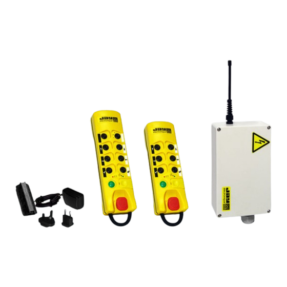
Serie : ../..Serie : ../..Alim : ...V.. Date : .. / .. IP65 Date : .. / .. IP65 Chargeur pour pack accumulateur UCCU (110-230VAC / 5VDC avec prises EU et UK) - 1 0 - UC 323882G... -
Page 11: Configuration À La Livraison
- L'émetteur est livré "déverrouillé", les configurations "durée de la temporisation pour la fonction Mise en veille" et "Fréquence" correspondant à la clé électronique peuvent être directement modifiées par un opérateur formé (voir § 6.3 pour les modes opératoires). -11- UC 323882G... -
Page 12: Type Et Spécification Des Boutons De L'émetteur
Bouton n°1 Bouton n°2 B1-B2 (face avant de l'UCE) Pour chacun des interverrouillages désigné, l’action simultanée sur les 2 boutons entraîne la désactivation des 2 ordres (mise à OFF des relais correspondants) - 1 2 - UC 323882G... -
Page 13: Correspondance Entre Boutons De Fonction Et Relais Du Récepteur
Voir les exemples de schémas de câblage en annexe D D D D D et E E E E E . (1) = 2 relais de sécurité (RS1 et RS2) + 1 relais «Klaxon» (RK) -13- UC 323882G... -
Page 14: Identification Des Produits
Emetteur UCE avec : UCEC22220 (869MHz) 8 boutons poussoirs double vitesse + 1 bouton poussoir "Marche/Klaxon" + 1 bouton d'arrêt coup de poing livré avec : 1 pack accumulateur (réf.UWB) + 1 planche d'étiquettes (réf.UWE207) - 1 4 - UC 323882G... -
Page 15: Récepteur Ucr
UCRAB42 UCRABL2 UCRABM2 869 MHz récepteur avec relais 2ème vitesse commun pour les boutons Description de la configuration des relais poussoirs double vitesse (1) = 2 relais de sécurité (RS1 et RS2) + 1 relais «Klaxon» (RK) -15- UC 323882G... -
Page 16: Références Des Ensembles Standards
(4)= Nécessite le kit prise tuner BNC Réf. : OWR01 (5)= Ne convient pas pour une connexion directe à l’antenne Réf. : VUB086, utiliser dans ce cas-là une rallonge intermédiaire type VUB1••. (6)= Nécessite la carte liaison UCWR32. - 1 6 - UC 323882G... -
Page 17: Caratéristiques Techniques
1 voyant vert "marche" et diagnostic (1) = La portée radio varie suivant les conditions d’environnement, l’antenne de réception et sa position (la portée diminue en cas d'obstacles métalliques tels que : charpentes métalliques, parois métalliques, enceintes métalliques etc...). -17- UC 323882G... -
Page 18: Clé Électronique
(2 clignotements) ainsi qu'un arrêt passif du récepteur. Elle peut servir de moyen d'arrêt de l'émetteur si nécessaire. L'émetteur ne peut pas être mis en marche sans sa clé électronique - 1 8 - UC 323882G... - Page 19 UCWE22X) en nous fournissant 2 données : 1) le code d'identité du récepteur (code de 4 digits, inscrit sur l'étiquette signalétique du récepteur UCR) 2) la référence de l’émetteur UCE IMPORTANT : Stocker la clé électronique dans un endroit sûr et repéré. -19- UC 323882G...
-
Page 20: Fonction "Mise En Veille" (Arrêt Automatique De L'émetteur Uce)
La durée N de la temporisation peut être modifiée par un opérateur formé, suivre la procédure décrite au § 6.3.3 La durée de temporisation pour la fonction "Mise en veille" est stockée dans la clé électronique de l'émetteur UCE. - 2 0 - UC 323882G... -
Page 21: Récepteur Ucr
(2) = «Arrêt actif» provoqué par appui sur le bouton d’arrêt coup de poing sur l’émetteur. (3) = Le bouchon peut être remplacé par un presse étoupe en plastique de type PG M16 qui se monte en lieu et place. -21- UC 323882G... -
Page 22: Raccordement Aux Sorties Relais
• 100 000 commutations à 250 VAC, 8 A, cosphi=1 • 100 000 commutations à 24 VDC, 6 A • Essais selon EN 60947-5-1 : DC13 à 2 A / 24 VDC AC15 à 3 A / 250VAC - 2 2 - UC 323882G... - Page 23 Commutation sous 230VAC (70VA,cosphi=0,75) 2 x 10 2 x 10 CA2DN LC1D09 Commutation sous 110VAC, (70VA,cosphi=0,75) 1 x 10 1 x 10 LC1D18 LC2D09 Commutation sous 48VAC (70VA,cosphi=0,75) 0,5 x 10 0,5 x 10 -23- UC 323882G...
-
Page 24: Protection De La Carte Récepteur Et Des Relais
Pas de protection Relais "Klaxon" Pas de protection Relais de fonction Pas de protection Le kit réf. PR0123 contient tous les fusibles pour toutes les configurations possibles de carte. - 2 4 - UC 323882G... -
Page 25: Pack Accumulateur Débrochable Uwb
Insertion du pack remplacement. accumulateur au dos de Si tel n'était pas le cas, un message d'erreur de l’émetteur type 5 clignotements causé par des micro-coupures d'alimentation pourrait apparaître (suivant tableau des messages d'erreur généré par l'émetteur). -25- UC 323882G... -
Page 26: Visualisation De L'état De Charge Du Pack Accumulateur
Le voyant est de couleur vert : ..... charge lente et de maintien (charge de l'UWB > ou = à 60%) Seul le chargeur UCCU de Jay Electronique est adapté pour recharger le pack accumulateur UWB. Voyant de l'émetteur : Deux fonctions de visualisation de l’état de charge de la batterie sont présentes... -
Page 27: Recommandations D'installation
5.3- Repérage de l'équipement commandé Si plusieurs appareils sont équipés de télécommandes, travaillant dans le même voisinage (par exemple dans une usine), chaque émetteur et chaque clé électronique doivent porter une indication claire qui indique au conducteur l'équipement qu'il commande. -27- UC 323882G... -
Page 28: Position Du Récepteur Et De L'antenne
La bonne orientation de l'antenne est indiquée sur la figure ci dessous : Correct Correct Correct Incorrect En l'absence d'un connecteur spécifique comme l'adaptateur pour antenne débrochable/déportée ref: OWR01, l'antenne du récepteur ne doit pas être modifiée. - 2 8 - UC 323882G... -
Page 29: Câblage
- Insérer le fil, - Retirer le tournevis. Ne pas effectuer de mouvement de levier sur le tournevis afin d'éviter d'endommager le bornier et le circuit imprimé de la carte mère du récepteur UCR. -29- UC 323882G... -
Page 30: Câblage De L'alimentation Électrique Du Récepteur Ucr
(étiquette sur le couvercle du boitier) et l'Annexe B. un exemple de câblage est donné en Annexe D et B pour les ensembles standard - 3 0 - UC 323882G... -
Page 31: Protection De L'alimentation Électrique
5.8- Commande de secours Des dispositions doivent être prises pour assurer que lorsque la radiocommande est hors service, un autre système de commande peut être utilisé pour permettre la sécurité de l'opérateur et de la charge manipulée. -31- UC 323882G... -
Page 32: Mise En Service Et Utilisation
§6.3.3. • Limites de portée radio : Tester la limite de portée entre l’émetteur et le récepteur (en vous déplaçant jusqu'à la limite de portée). - 3 2 - UC 323882G... -
Page 33: Vérifications Périodiques Et Suite À Une Opération De Maintenance
NB : Si cette procédure n'est pas respectée l'émetteur signale une erreur de type 3 clignotements (reprendre alors la procédure décrite au §6.3.4) ou 5 clignotements (erreur d’arrêt ou de mise en route) de ses voyants rouge et vert. Voir le Synoptique de fonctionnement en page suivante -33- UC 323882G... -
Page 34: Synoptique De Fonctionnement
6.2.1- Synoptique de fonctionnement - 3 4 - UC 323882G... -
Page 35: Configuration De L'émetteur Uce
§6.3.1. n°5 n°6 Bouton de n°3 programmation n°4 n°3 Bouton de Bouton de n°1 n°2 programmation programmation n°1 n°2 Bouton d’arrêt coup de poing voir pages suivantes pour les modes opératoires de configuration -35- UC 323882G... -
Page 36: De L'accés À La Programmation De L'émetteur Uce
"émetteur verrouillé", traduite par des clignotements en alternance de ses voyants. Verrouillage Déverrouillage n°4 n°3 n°4 n°4 n°3 n°3 n°1 n°2 n°1 n°2 n°1 n°2 Fig.1 Fig.2 Fig.3 n°3 n°4 n°2 n°1 n°1 n°2 DATA Mémoire clé Fig.4 Fig.5 Fig.6 - 3 6 - UC 323882G... -
Page 37: Programmation : Canal Radio De Travail
§ 6.2. n°5 n°6 n°3 n°4 n°3 n°4 n°3 n°4 n°2 n°1 n°1 n°2 n°1 n°2 Fig.1 Fig.2 Fig.3 n°3 n°4 n°2 n°1 n°1 n°2 DATA n°5 n°6 n°3 n°4 n°1 n°2 Fig.4 Fig.5 Fig.6 -37- UC 323882G... -
Page 38: Programmation : Durée De La Temporisation Fct "Mise En Veille
(fig.6). n°5 n°6 n°3 n°4 n°3 n°4 n°4 n°3 n°1 n°2 n°1 n°2 n°1 n°2 Fig.1 Fig.2 Fig.3 n°3 n°4 n°2 n°1 n°1 n°2 DATA Mémoire clé Fig.4 Fig.5 Fig.6 - 3 8 - UC 323882G... -
Page 39: Programmation : Recopie Du Code D'identité De La Clé Dans L'uce
Fig.4 Une programmation de la fréquence de travail est peut être nécessaire (par exemple si la nouvelle clé électronique est programmée sur une autre fréquence), suivre alors la procédure décrite au §6.3.2. -39- UC 323882G... -
Page 40: Fonction Des Voyants De L'émetteur Uce
- Bouton d'arrêt coup de poing défectueux Avant appui sur le bouton 7 clignotements 7 clignotements Erreur interne de la clé électronique "marche" Avant appui sur le bouton 8 clignotements 8 clignotements Erreur interne de l'émetteur UCE "marche" - 4 0 - UC 323882G... - Page 41 «mise paramètre paramètre en veille» mort" ou du canal radio configuré configuré Verrouillage-déverouillage de l'accés à la Allumé Eteint émetteur verrouillé programmation Verrouillage-déverouillage de l'accés à la Allumé Allumé émetteur non verrouillé programmation -41- UC 323882G...
-
Page 42: Configuration Du Récepteur Ucr
3 clignotements EEPROM 4 clignotements En cas de défaut Indique un défaut 5 clignotements 6 clignotements Type de micro 7 clignotements Récepteur hors tension LED V1 Indication de Tous Alimentation l'alimentation (VERT) Récepteur sous tension - 4 2 - UC 323882G... -
Page 43: Etiquetage Des Boutons De Fonction De L'émetteur
7 8 9 n°5 n°6 • • n°4 n°3 • • • • n°2 n°1 bouton n°3 n°5 n°1 n°2 n°6 n°4 Cependant, l'installateur est libre de repérer les mouvements de l'appareil commandé de manière la plus ergonomique. -43- UC 323882G... - Page 44 Référence : Kit de 48 étiquettes vierges (blanches) + 48 étiquettes UWE205 transparentes de protection, pour marquage personnalisé - 4 4 - UC 323882G...
-
Page 45: Entretien
électronique et à celui du pack accumulateur. - Procéder au nettoyage de l’émetteur en éliminant tout corps étranger y adhérant. N'utiliser que des nettoyants non agressifs à base de solution savonneuse. -45- UC 323882G... - Page 46 - Pour vérifier le fonctionnement de l'arrêt passif, il suffit d'enlever la clé électronique de l'émetteur ou son pack accumulateur ou d'attendre l'activation de la fonction "MISE EN VEILLE", les relais de sécurité du récepteur doivent alors retomber en moins de 2 secondes. - 4 6 - UC 323882G...
-
Page 47: Maintenance
2. La structure de l'UC limite les interventions au niveau 1 pour l'utilisateur final. Les interventions de niveau 2 se feront dans une station technique agréée JAY Electronique. -47- UC 323882G... -
Page 48: Compatibilité Avec La Série Ud
2 clignotements des voyants de l'émetteur). - Un émetteur UCE ne peut pas commander un récepteur UDR. - Le pack accumulateur UWB doit impérativement être chargé avec le chargeur UCCU, il ne peut l'être avec le chargeur UBCU. - 4 8 - UC 323882G... -
Page 49: Garantie
été effectués par le client sans l' accord écrit de notre Société. La responsabilité de la Société JAY Electronique pendant la période de garantie est limitée à tout vice de matière ou de construction; elle comprend la réparation en ses ateliers ou le remplacement gratuit des pièces reconnues défectueuses après... - Page 50 - 5 0 - UC 323882G...
- Page 51 UC SY UC SY STEM STEM UC SY STEM STEM UC SY UC SY STEM -51- UC 323882G...
- Page 52 Choice of operating radio frequency ..........p. 75 Marking of the controlled equipment ........... p. 75 Receiver and antenna positions ............p. 76 Wiring ....................p. 77 5.5.1 Wiring the receiver UCR ..............p. 77 - 5 2 - UC 323882G...
- Page 53 CE Declaration of conformity / Transmitter UCE ....... p. 159 CE Declaration of conformity / Receiver UCR ......p. 160 BNC antenna plug kit installation, ref.:OWR01 ......p. 161 «Help us improve this manual» form ............p. 162 -53- UC 323882G...
-
Page 54: General Safety Rules
Never leave the radio control transmitter on the ground or on a metal surface. If doing so becomes indispensable, press the stop palmswitch on the radio control. - 5 4 - UC 323882G... - Page 55 + battery pack. Service your equipment and perform all periodic checks as may be required by the intensity with which your equipment is used. -55- UC 323882G...
-
Page 56: Description Of Uc Radio Remote Control
The radio remote control completes and enhances the classic safety circuits (emergency stop circuits). With the UC radio remote controls, Jay Electronique provides solutions to the broad range of standard industrial lifting applications. Besides, a special attention has been given to ensure operator comfort through the following features : ... - Page 57 For any recommendations or questions concerning installation of the UC remote control system, contact us at our customer service department : Tel : +33.(0)4.76.41.44.55 Fax: +33.(0)4.76.41.44.44 customer.service@jay-electronique.com -57- UC 323882G...
-
Page 58: Unpacking The Products
Freq : 433,050 .. 434,790MHz Serie : ../..Serie : ../..Alim : ...V.. Date : .. / .. IP65 Date : .. / .. IP65 Battery pack charger UCCU (110-230VAC / 5VDC with European and English plugs) - 5 8 - UC 323882G... -
Page 59: Delivery Configuration
• Locking of the access to programming of transmitter URE : - The transmitter is supplied "unlocked", the "Standby" duration and "Frequency" configurations corresponding to the electronic key can be directly modified by a trained operator. (see programming procedures on § 6.3). -59- UC 323882G... -
Page 60: Type And Specification Of Function Buttons On Uce
Button n°4 B3-B4 n°2 n°1 Button n°1 Button n°2 B1-B2 (UCE front view) For each of the indicated interlocked pair, simultaneous action on the two buttons deactivates the commands (corresponding relays set to OFF). - 6 0 - UC 323882G... -
Page 61: Correspondence Between Function Buttons And Receiver Relays
A recapitulative label of these correspondences is sticked on UCR receiver housing cover. See wiring examples for standard units in appendices D and E (1) = 2 safety relays (RS1 et RS2) + 1 «Horn» relay (RK) -61- UC 323882G... -
Page 62: Product Identification
Transmitter UCE with : UCEC22220 (869MHz) 8 two-step pushbuttons (double speed) + 1 "On/Horn" button + 1 stop palmswitch button delivered with : 1 battery pack (ref. UWB ) + 1 label kit "movements" (ref. UWE207 ) - 6 2 - UC 323882G... -
Page 63: Ucr Receiver
Power supply UCR0B42 UCR0BL2 UCR0BM2 433-434 MHz Receiver UCRAB42 UCRABL2 UCRABM2 869 MHz reference Relay configuration With common second speed relay for two-step pushbuttons description (1) = 2 safety relays (RS1 + RS2) + 1 «Horn» relay (RK) -63- UC 323882G... -
Page 64: Standard Unit Reference
(4) = Require BNC tuner connector kit ref.: OWR01 (5) = Not suitable for direct connection to antenna ref.: VUB086, in this case, use an intermediate extension type VUB1••. (6) = Require serial link board ref.: UCWR32 - 6 4 - UC 323882G... -
Page 65: Technical Characteristics
1 green indicator light "On" and "diagnostic" (1) = The range varies according to environment conditions, the reception antenna and its position (the range is decreased in case of metal obstacles such as: metal frameworks, walls etc.) -65- UC 323882G... -
Page 66: Identity Code
(2 flashes) and passive shutdown of the receiver. If necessary, it can be used to stop the transmitter. The transmitter cannot be started up without its electronic key. - 6 6 - UC 323882G... - Page 67 2 parameters : 1) the receiver identity code (code on 4 digits, on receiver descriptive label). 2) the UCE transmitter reference (on transmitter descriptive label). IMPORTANT : Store the electronic key in a safe, identified location. -67- UC 323882G...
-
Page 68: Standby" Function (Automatic Shutdown Of Uce)
Changing the «standby» duration: : The standby duration N can be modified by a trained operator by performing the procedure described in § 6.3.3. The duration is stored in the UCE transmitter electronic key. - 6 8 - UC 323882G... -
Page 69: Ucr Receiver
(2) = «Active Stop» caused by action on the transmitter stop palmswitch button. (3) = The cap can be replaced by a plastic cable gland (standard PE) type PG M16 mounted in its place. -69- UC 323882G... -
Page 70: Connection To Relay Outputs
• 100 000 switching cycles at 250 VAC, 8 A, cosphi=1 • 100 000 switching cycles at 24 VDC, 6 A • Tests per EN 60947-5-1 : DC13 at 2 A / 24 VDC AC15 at 3 A / 250VAC - 7 0 - UC 323882G... - Page 71 "Control" relays Switching at 230VAC (70VA,cosphi=0,75) 2 x 10 2 x 10 CA2DN LC1D09 Switching at 110VAC, (70VA,cosphi=0,75) 1 x 10 1 x 10 LC1D18 LC2D09 Switching at 48VAC (70VA,cosphi=0,75) 0,5 x 10 0,5 x 10 -71- UC 323882G...
-
Page 72: Protection Of Receiver Board And Relays
1 A / 250 VAC / T Safety relays No protection "Horn" relay No protection "control" relays No protection The kit PR0123 contains all the fuses required for all the possible board configurations. - 7 2 - UC 323882G... -
Page 73: Uwb Plug-In Battery Pack
Insertion of battery pack back of the transmitter. in the back of transmitter If not, a type 5 fault caused by power supply micro-cutouts can occur (following fault list generated by the transmitter) -73- UC 323882G... -
Page 74: Display Of Battery Pack Charge State
The indicator light is orange : ....... fast charge The indicator light is green : ......slow and up-keep charge (UWB charge > or = 60%) The JAY Electronique charger UCCU is perfectly suited to charge the UWB battery pack. Indicator light on the transmitter: Two battery charge status display functions are provided on the transmitter : •... -
Page 75: Installation Recommendations
If there are several equipment fitted with similar radio remote control systems working in the same neighbourhood (e.g. in a plant), each transmitter shall carry a clear indication which tells the equipment driver which equipment is controlled by the transmitter in question. -75- UC 323882G... -
Page 76: Receiver And Antenna Positions
The antenna orientation is indicated in the figure below: Good Good Good Wrong Unless a special connector such as the plug-in antenna adapter ref. OWR01 (accessory) is used, the receiver antenna should not be modified. - 7 6 - UC 323882G... -
Page 77: Wiring
- Remove the screwdriver. Do not apply any lever movement to the screwdriver as this can result in damaging the terminal strip and the printed circuit on the motherboard of the receiver UCR. -77- UC 323882G... -
Page 78: Wiring The Electrical Power Supply Of Receiver Ucr
For the wiring and to determine the correspondence between the action on a function button and the relay controlled, refer to the configuration table supplied with the receiver (label on housing cover) and Appendix B. See wiring example in Appendix D and E for standard units. - 7 8 - UC 323882G... -
Page 79: Electrical Power Supply Protection
5.8- Auxiliary control Measures should be taken to ensure, that when the radio control is not in service, another control system can be used to ensure the safety of the operator and the manipulated load. -79- UC 323882G... -
Page 80: Commissioning And Operation
§ 6.3.3. • Radio range limits : In transmit mode, evaluate the range limit between transmitter and receiver (by moving up to the range limit). - 8 0 - UC 323882G... -
Page 81: Periodic Checks Performed Following Maintenance Operations
NB : If this procedure is not observed the transmitter indicates an error of the type 3 flickerings (repeat procedure described on §6.3.4) or 5 flickerings (error of stop or startup) of its red and green indicator lights. See functioning block diagram on next page -81- UC 323882G... -
Page 82: Functioning Block Diagram
6.2.1- Functioning block diagram - 8 2 - UC 323882G... -
Page 83: Configuring The Uce Transmitter
§ 6.3.1. n°5 n°6 Programming n°3 button n°4 n°3 Programming n°2 button Programming n°2 n°1 n°1 button Stop palmswitch button See next pages for configuration procedures -83- UC 323882G... -
Page 84: Procedure : Locking-Unlocking Access To Programming Of Uce
Locking Unlocking n°4 n°3 n°4 n°4 n°3 n°3 n°1 n°2 n°1 n°2 n°1 n°2 Fig.1 Fig.2 Fig.3 n°3 n°4 n°2 n°1 n°1 n°2 DATA Electronic memory Fig.4 Fig.5 Fig.6 - 8 4 - UC 323882G... -
Page 85: Procedure : Programming The Working Radio Frequency
§ 6.2. n°5 n°6 n°3 n°4 n°3 n°4 n°3 n°4 n°2 n°1 n°1 n°2 n°1 n°2 Fig.1 Fig.2 Fig.3 n°3 n°4 n°2 n°1 n°1 n°2 DATA n°5 n°6 n°3 n°4 n°1 n°2 Fig.4 Fig.5 Fig.6 -85- UC 323882G... -
Page 86: Procedure : "Standby" Function Time Programming
6- Exit the "Standby" time programming mode by pressing the stop palmswitch button (fig.6). n°5 n°6 n°3 n°4 n°3 n°4 n°3 n°4 n°2 n°1 n°1 n°2 n°1 n°2 Fig.1 Fig.2 Fig.3 n°4 n°3 n°1 n°2 n°2 n°1 DATA Electronic memory Fig.4 Fig.5 Fig.6 - 8 6 - UC 323882G... -
Page 87: Procedure : Copying Electronic Key Identity Code In Uce
Fig.1 Fig.2 Fig.3 Fig.4 The working frequency may need to be programmed (for example, if the new electronic key is programmed on another frequency), Perform then the procedure described on § 6.3.2. -87- UC 323882G... -
Page 88: Uce Transmitter Indicator Light Functions
-Transmitter stop palmswitch button faulty Before "On/horn" button is Flashes 7 times Flashes 7 times Internal electronic key error pressed Before "On/horn" button is Flashes 8 times Flashes 8 times Internal UCE transmitter error pressed - 8 8 - UC 323882G... - Page 89 "Dead man" time or radio Indicates tens or units of parameter of parameter frequency configured configured Procedure : Locking - unlocking Transmitter is locked access to programming Procedure : Locking - unlocking Transmitter is unlocked access to programming -89- UC 323882G...
-
Page 90: Configuring The Ucr Receiver
3 flashes EEPROM 4 flashes In case of fault Indicates a fault 5 flashes 6 flashes Micro type 7 flashes Receiver switched OFF V1 led Indicates power power supply supply state (Green) Receiver switched ON - 9 0 - UC 323882G... -
Page 91: Uce Transmitter Function Button Labels
• • n°4 n°3 • • • • n°2 n°1 button n°3 n°5 n°1 n°2 n°6 n°4 However, the installer is free to mark the movements of the controlled device in a most ergonomic way. -91- UC 323882G... - Page 92 Reference : Kit of 48 white blank labels, «customization» + 48 transparent UWE205 protecting labels. - 9 2 - UC 323882G...
-
Page 93: Servicing
- Clean the transmitter by eliminating any foreign matter. Only use non aggressive cleaning product on base of soapy solution. -93- UC 323882G... - Page 94 - To check operation of the passive stop function, simply remove the electronic key or battery pack from the transmitter or wait until "Standby" function duration is exceeded ; receiver safety relays should de-energise within 2 seconds. - 9 4 - UC 323882G...
-
Page 95: Maintenance
These parts are only accessible to end users having successfully completed a level 2 training course. The UC structure limits level 1 interventions for the end user. The level 2 interventions are performed in a technical center approved by JAY Electronique -95- UC 323882G... -
Page 96: Compatibility With Ud Series
2 flashes of the indicator lights) - An UCE transmitter cannot control an UDR receiver. - The UWB battery pack necessarily has to be charged with UCCU charger, it cannot be charged with UBCU charger. - 9 6 - UC 323882G... -
Page 97: Warranty
The warranty shall not apply subsequent to any modifications or additions to the equipment performed by the customer without written approval by JAY Electronique. The JAY Electronique responsability during the warranty period is limited to material and construction defects. This warranty comprises repair in the JAY workshops or replacement, free of charge, of parts recognized to be defective following expert inspection by the Jay Technical Department. - Page 98 - 9 8 - UC 323882G...
- Page 99 Funkf er nsteuer ung ung en Funkf Funkf nsteuer mit T T T T T asten asten asten asten asten Serie UC Serie UC Serie UC Serie UC Serie UC -99- UC 323882G...
- Page 100 Installationsempfehlungen .......... s. 123 Entstörung ..................s. 123 Wahl der verwendeten Funkfrequenz ..........s. 123 Kennzeichnung der gesteuerten Ausrüstung ........s. 123 Position des Empfängers ..............s. 124 Verkabelung ..................s. 125 5.5.1 Verkabelung des Empfängers UCR ..........s. 125 -100- UC 323882G...
- Page 101 Liste der verfügbaren Frequenzen ..........s. 158 CE Konformitätserklärung / Sender UCE ........s. 159 CE Konformitätserklärung / Empfänger UCR ......s. 160 Einsetzen des abnehmbaren BNC-Antenne-Kits ref : OWR01 ... s. 161 Formular für Verbesserungsvorschläge für dieses Handbuch ... s. 162 -101- UC 323882G...
-
Page 102: Allgemeine Benutzungsvorschriften
Den Sender nicht an einem beliebigen Platz zurücklassen, auch wenn dieser mit einer automatischen Trennvorrichtung der Art «Standby» ausgestattet ist. Den Sender der Funkfernsteuerung nicht auf den Boden legen. Sollte dies dennoch unbedingt erforderlich sein, muss die Fernsteuerung abgeschaltet werden (Not-Stopp-Schlagschalter). -102- UC 323882G... - Page 103 Bei auftretenden Anomalien, das Gerät sofort durch Betätigung der Aus-Taste des Senders ausschalten und den elektronischen Schlüssel abziehen. Die Ausrüstung pflegen, und je nach Betriebsintensität regelmäßig überprüfen. Die im Kapitel «Pflege» beschriebenen Reinigungsvorschriften unbedingt befolgen. -103- UC 323882G...
-
Page 104: Vorstellung Der Funkfernsteuerung Serie Uc
Funkfernsteuerung hebt herkömmlichen Sicherheitskreise (Beispiel: Notaus) nicht auf, sondern ergänzt sie. Mit den Funkfernsteuerungen der Reihe UC bietet JAY Electronique Lösungen für die industrielle Standard-Förderung Darüber hinaus wurde der einfachen Handhabbarkeit durch den Bediener besondere Aufmerksamkeit gewidmet: Ergonomischer Sender für Steuern mit einer Hand ... - Page 105 Telekommunikationsterminals (Niederspannung, Elektromagnetische Verträglichkeit, Funkspektrum): Zertifikat ART Für Probleme in Bezug auf Betrieb oder Installierung des Funkfernsteuerungssystems UC wenden Sie sich bitte an unseren Kundendienst : Tel : +33.(0)4.76.41.44.55 Fax: +33.(0)4.76.41.44.44 customer.service@jay-electronique.com -105- UC 323882G...
-
Page 106: Auspacken Der Elemente
Freq : 433,050 .. 434,790MHz Serie : ../..Serie : ../..Alim : ...V.. Date : .. / .. IP65 Date : .. / .. IP65 Ladegerät für Akkupack UCCU (110-230VAC / 5VDC mit EU, und UK Stecker) -106- UC 323882G... -
Page 107: Konfigurierung Bei Lieferung
- Der Sender wird mit einem "freigegebenen" elektronischen Schlüssel geliefert, die Parameter: Funkfrequenz und Dauer der Zeitspanne der "Standby"-Funktion können direkt von einem dafür geschulten und befugten Mitarbeiter programmiert werden (beziehen Sie sich für die Vorgehensweise auf das Kapitel "Konfigurierung des Senders" § 6.3). -107- UC 323882G... -
Page 108: Typ Und Beschreibung Der Funktionstasten
Taste Nr. 3 Taste Nr. 4 B3-B4 n°2 n°1 Taste Nr. 1 Taste Nr. 2 B1-B2 (Vorderseite des UCE) Durch den Druck auf beide Tasten der Zwischenverriegelung werden beide Befehle deaktiviert (Stellung der entsprechenden Relais auf OFF). -108- UC 323882G... -
Page 109: Zuordnung "Funktionstasten Sender / Empfänger-Relais
UCR stecken. Siehe Beispiele von Schaltplänen im Anhang D D D D D und E E E E E . (1) = 2 Sicherheitsrelais (RS1 und RS2) + 1 Relais «Hupe» (RK) -109- UC 323882G... -
Page 110: Produktidentifikation
1 Akkupack (ref.UWB) + 1 Etikettenblatt (ref.UWE207) Beschreibung der Tastenkonfiguration Referenz Sender UCE222220 (433-434MHz) Sender UCE mit : UCEC22220 (869MHz) 8 "2-Gang" Drucktasten + 1 Drucktaste "Ein/Hupe" + 1 Notaustaste Geliefert mit: 1 Akkupack (ref.UWB) + 1 Etikettenblatt (ref.UWE207) -110- UC 323882G... -
Page 111: Empfänger Ucr
48 - 230 VAC UCR0B42 UCR0BL2 UCR0BM2 433-434 MHz Referenz UCRAB42 UCRABL2 UCRABM2 869 MHz Empfänger Mit gemeinsamen Relais für den 2.Gang bei Beschreibung der Relaiskonfiguration Zweigangdrucktasten (1) = 2 Sicherheitsrelais (RS1 et RS2) + 1 Relais «Hupe» (RK) -111- UC 323882G... -
Page 112: Standardpäck Referenz
(4) = Benötigt den BNC-Steckverbindungssatz Artikelnummer ref.: OWR01 (5) = Nicht geeignet für einen direkten Anschluss an eine ref.: VUB086-Antenne, in diesem Fall eine Verlängerung vom Typ VUB1•• benutzen. (6) = Benötigt den Serielle Verbindungskarte Artikelnummer ref.: UCWR32 -112- UC 323882G... -
Page 113: Technische Daten
Vom Benutzer programmierbare Zeitspanne (01 bis 98 mn) Signalisation 1 rote Kontrolleuchte "Batterie leer" und "Diagnose" 1grüne Kontrolleuchte "Ein" und "Diagnose" (1) = Die Reichweite variiert je nach den Umgebungbedingungen des Senders und der Empfängerantenne (Dachstühle, Metallwände, etc.) -113- UC 323882G... -
Page 114: Identitätscode
Entnahme vor Drücken des Not-Stopp-Schlagschalters löst eine Fehlermeldung (2 malige blinken) und eine passive Abschaltung des Empfängers aus. Er kann ggf. als Abschaltmöglichkeit des Senders verwendet werden. Der Sender kann ohne den elektrischen Schlüssel nicht betrieben werden -114- UC 323882G... - Page 115 Angabe der 2 folgenden Daten bestellen : 1) Den Identitätscode des Empfängers (dem Kennzeichnungsschild des UCR-Empfängers zu entnehmen) sowie die Konfigurierung der Tasten des UCE-Senders. 2) Referenz des Senders WICHTIG : Bewahren Sie den elektronischen Schlüssel an einem sicheren Ort und markiert. -115- UC 323882G...
-
Page 116: Standby"-Funktion
Änderung der Dauer der Zeitspanne : Die Dauer N der Zeitspanne kann durch einen hierfür geschulten und befugten Nutzer und Befolgung des Verfahrens in § 6.3.3 geändert werden. Die Verzögerungszeit für die "Standby"-Funktion ist in den elektronischen Schlüssel gespeichert. -116- UC 323882G... -
Page 117: Empfänger Ucr
(1) = Passives Abschaltsystem bei Störung der Funkverbindung oder entladene Batterie oder abgetrennter Batterie (2) = Active Abschaltsystem durch Drücken des Not-Aus-Taste auf dem Sender. (3) = Der Stopfen kann durch eine PG-Verschraubung aus Kunststoff Typ PG M16 ausgetauscht werden, die stattdessen angebracht wird. -117- UC 323882G... -
Page 118: Relaisanschluß
• 100 000 Umschaltungen bei 250 VAC, 8 A, cosphi=1 • 100 000 Umschaltungen bei 24 VDC, 6 A • Versuche nach EN 60947-5-1 : DC13 bei 2 A / 24 VDC AC15 bei 3 A / 250VAC -118- UC 323882G... - Page 119 Größe Sicherheitsrelais Steuerrelais Umschaltung bei 230VAC (70VA,cosphi=0,75) 2 x 10 2 x 10 CA2DN LC1D09 Umschaltung bei 110VAC, (70VA,cosphi=0,75) 1 x 10 1 x 10 LC1D18 LC2D09 Umschaltung bei 48VAC (70VA,cosphi=0,75) 0,5 x 10 0,5 x 10 -119- UC 323882G...
-
Page 120: Schutz Der Empfängerkarte Und Der Relais
160 mA / 250 VAC / T Versorgung des Empfängers mit 24VDC 1 A / 250 VAC / T Sicherheitsrelais Kein Schutz Ein/Hupe Relais Kein Schutz Funktion Relais Kein Schutz kit Sicherungen ref.Nr.: PR0123 -120- UC 323882G... -
Page 121: Herausnehmbarer Akkupack Uwb
Bucht an der Rückseite de UCE- Senders sitzt. Einsetzen des Akkupacks in die Rückseite des Senders Sollte dies nicht der Fall sein, erscheint durch eventuelle Auftreten Mikro- Unterbrechungen der Stromversorgung eine Fehlermeldung von Typ 5 (siehe Tabelle der vom Sender ausgegebenen Fehlermeldungen). -121- UC 323882G... -
Page 122: Visualisierung Des Ladezustands Des Akkupacks
Wartungsladevorgang (der Ladestand beträgt UWB > oder = 60%) Nur das Ladegerät der Art.-Nr. UCCU von Jay Electronique ist für das Laden des Akkupacks UWB geeignet. Kontrolllampe des UCE-Senders : Der Sender verfügt über zwei Visualisierungsfunktionen des Ladestands der Batterie : •... -
Page 123: Installationsempfehlungen
Wenn mehrere Hebevorrichtungen mit hängender Last mit Funkfernsteuerungen ausgerüstet sind und in unmittelbarer Nachbarschaft arbeiten (z.B. in einer Werkhalle), muß jeder Sender eine klare Kennzeichnung tragen, die dem Führer der Hebevorrichtung zweifelsfrei die Last angibt, die er steuert. -123- UC 323882G... -
Page 124: Position Des Empfängers
Die korrekte Ausrichtung der Antenne wird in der Abbildung unten dargestellt : Nicht GUT Wenn keine besondere Steckverbindung wie ein Adapter für abnehmbare Antennen Art.-Nr: OWR01 vorhanden ist, darf die Antenne des Empfängers nicht umgerüstet werden -124- UC 323882G... -
Page 125: Verkabelung
Kabel einführen, - das Kabel einführen, - den Schraubenzieher herausziehen. Keine Hebelbewegung auf den Schraubenzieher ausüben, um Beschädigungen der Klemmleiste und der gedruckten Schaltung der Grundkarte des Empfängers UCR zu vermeiden.. -125- UC 323882G... - Page 126 Für die Verkabelung und für die Entsprechung zwischen der Betätigung einer Funktionstaste oder eines Schalters und dem gesteuerten Relais siehe dem Empfänger bei der Lieferung beiliegende Entsprechungstabelle (Etikett auf dem Gehäusedeckel) und Anhang B. Im Anhang D befindet sich ein Beispiel für ein Schaltbild -126- UC 323882G...
-
Page 127: Schutz Der Elektrischen Stromversorgung
Last oder Zwischenrelais installieren (Nebenkontakte im Schaltschrank für die Leistungssteuerung zum Beispiel). 5.8- Notsteuerung Es müssen Maßnahmen getroffen werden, damit bei Ausfall der Funkfernsteuerung ein anderes Steuerungssystem benutzt werden kann, um die Sicherheit des Bedieners und der hängenden Last zu gewährleisten. -127- UC 323882G... -
Page 128: Inbetriebnahme Und Betrieb
Bediener durch Befolgen des unter §6.3.3 beschriebenen Verfahrens erfolgten Änderung entspricht. • Grenzen der Funkreichweite : Die Funkreichweite zwischen Sender und Empfänger testen (indem Sie sich bis zu den Grenzen der Reichweite bewegen). -128- UC 323882G... -
Page 129: Regelmäßige Kontrollen Und Kontrollen Nach Wartungsvorgängen
Kontrollleuchten des Senders blinken 5 mal, hören kurz auf und blinken dann erneut 5 mal, etc...): Fehler bei In- oder Außerbetriebnahme (vergewissern Sie sich, dass der Akkupack korrekt angebracht ist und setzen Sie das Verfahren der Inbetriebnahme fort). Siehe Start-Synoptik auf der folgenden Seite -129- UC 323882G... -
Page 130: Synoptik Der Startfunktion
6.2.1- Synoptik der Startfunktion -130- UC 323882G... -
Page 131: Konfigurierung Und Parametrierung Des Uc-Systems
Empfänger öffnen zu müssen. Durch ein besonderes Betriebsverfahren kann der Teamleiter den Zugang zur Programmierung verriegeln oder entriegeln (Siehe §6.3.1). Programmier-Taste Nr.3 n°4 n°3 Programmier-Taste n°1 n°2 Programmier-Taste Nr.1 Nr.2 Not-Stopp-Schlagschalter Siehe nächste Seiten für die Vorgehensweise zur Konfiguration -131- UC 323882G... -
Page 132: Programmierung : "Verriegelung - Entriegelung" Des Zugriffs Auf Die Programmierung Des Senders
«Sender verriegelt» durch das abwechselnde Blinken der Kontrollleuchten ab. Verriegelung Entriegelung n°4 n°3 n°4 n°4 n°3 n°3 n°1 n°2 n°1 n°2 n°1 n°2 Abb.1 Abb.2 Abb.3 n°3 n°4 n°2 n°1 n°1 n°2 DATA Schlüsselspeicher Abb.4 Abb.5 Abb.6 -132- UC 323882G... -
Page 133: Programmierung : Funkfrequenz
Funkkanal tatsächlich gewechselt hat § 6.2. n°5 n°6 n°3 n°4 n°3 n°4 n°3 n°4 n°2 n°1 n°1 n°2 n°1 n°2 Abb.1 Abb.2 Abb.3 n°3 n°4 n°2 n°1 n°1 n°2 DATA n°5 n°6 n°3 n°4 n°1 n°2 Abb.4 Abb.5 Abb.6 -133- UC 323882G... -
Page 134: ( " Standby "-Funktion)
6- Der Programmier-Modus "Dauer Standby-Funktion" kann durch Drücken des Not-Stopp-Schlagschalters verlassen werden (Abb.6). n°5 n°6 n°3 n°4 n°3 n°4 n°3 n°4 n°2 n°1 n°1 n°2 n°1 n°2 Abb.1 Abb.2 Abb.3 n°4 n°3 n°1 n°2 n°2 n°1 DATA Schlüsselspeicher Abb.4 Abb.5 Abb.6 -134- UC 323882G... -
Page 135: Programmierung : "Übertragung Des Identitätscodes Des Elektronischen Schlüssels In Den Uce-Sender
Abb.4 Eventuell muss die Arbeitsfrequenz neu programmiert werden (zum Beispiel wenn der neue elektronische Schlüssel auf eine andere Frequenz programmiert wurde). Befolgen Sie in diesem Fall das unter § 6.3.2 beschriebene Verfahren. -135- UC 323882G... -
Page 136: Funktion Der Kontrolleuchten Des Senders
Verbindung des Akkupacks. 6-faches Blinken 6-faches Blinken Vor "Ein" Sicherstellen, dass der Akkupack fest am Rücken des Senders sitzt ODER -Not-Aus-Taste defekt 7-faches Blinken 7-faches Blinken Internes Elektronikproblem Vor "Ein" 8-faches Blinken 8-faches Blinken Internes Elektronikproblem Vor "Ein" -136- UC 323882G... - Page 137 Programmierung Standby Funkkanal oder "Totmann"- Zehnerstellen Einheiten Angabe der Zahl Funktion Zugriff auf die Programmierung des UCE- Leuchtet ständig Verriegelung des Senders Senders Zugriff auf die Programmierung des UCE- Leuchtet ständig Leuchtet ständig Entriegelung des Senders Senders -137- UC 323882G...
-
Page 138: Konfigurierung Des Ucr-Empfängers
LED V2 Stromausfall 2 blinkt (ROT) "Ein" Relais 3 blinkt EEPROM 4 blinkt Bei Störungen Gibt Störung an 5 blinkt 6 blinkt CPU-Typ 7 blinkt Empfänger ausgeschaltet LED V1 Angabe Alle Power ON Stromversorgung (GRÜN) Empfänger eingeschaltet -138- UC 323882G... -
Page 139: Etikettierung Der Funktionstasten
Etiketten 4 5 6 1 2 3 • (für Tasten Nr.1 bis Nr.6) GATE 7 8 9 n°5 n°6 • • n°4 n°3 • • • • n°2 n°1 Taste Nr.3 Nr.5 Nr.1 Nr.2 Nr.6 Nr.4 -139- UC 323882G... - Page 140 Referenz : Set mit 48 unbes-chrifteten (weißen) Etiketten + 48 UWE205 durchsichtigen Schutz-etiketten für persönliche Kennzeichnung -140- UC 323882G...
-
Page 141: Pflege
Membranen der Funktionstasten, des Anschlusses des elektronischen Schlüssels und des Akkupacks achten. - Den Sender reinigen und alle Fremdkörper entfernen, die an ihm haften könnten. Nur nicht agressive Reinigungsmittel auf der Grundlage von Seifenlösungen benutzen. -141- UC 323882G... - Page 142 Abschaltung (UC System eingeschaltet) : dazu den elektronischen Schlüssel des Senders entnehmen oder den Akkupack abnehmen oder warten, bis die "Standby"-Funktion aktiviert ist (automatische Abschaltung des Senders). Die Sicherheitsrelais des Empfängers müssen innerhalb von weniger als 2 Sekunden abfallen. -142- UC 323882G...
-
Page 143: Wartung
Schulung der Stufe 2 absolviert haben. Der Aufbau der UC beschränkt die Eingriffe für den Endbenutzer auf das Niveau 1. Eingriff auf Niveau 2 erfolgt in einem von Jay Electronique zugelassenen technischen Stützpunkt. -143- UC 323882G... -
Page 144: Kompatibilität Mit Ud-Serie
Unvereinbarkeit von 2 blinkt der Lichter auf dem Sender zu arbeiten). - Ein UCE-Sender kann nicht steueren um ein UDR-Empfänger. - Der Akku sollte immer UWB mit Ladegerät UCCU geladen werden, kann es nicht mit dem Ladegerät UBCU werden. -144- UC 323882G... -
Page 145: Garantie
Die Garantie entfällt, wenn der Kunde Veränderungen oder Ergänzungen am Gerät vornimmt, ohne die schriftliche Zustimmung durch unser Unternehmen. Die Haftung des Unternehmens JAY Electronique beschränkt sich während der Garantiezeit auf Materialfehler oder Konstruktionsmängel; sie umfaßt die Reparatur in unserem Werk oder den kostenlosen Austausch defekter Teile nach Begutachtung durch einen unserer «Technischen Dienste». - Page 146 -146- UC 323882G...
- Page 147 • Annexes • Appendix • Anhang -147- UC 323882G...
- Page 148 -148- UC 323882G...
-
Page 149: A Emetteur Uce : Vue Externe Détaillée
L- Location of electronic key N- Akkupack UWB an die M- Bouton d'arrêt coup de poing M- Stop palmswitch button Rückseite des Senders N- Pack accumulateur connecté N- Battery pack in the back of angeschlossen au dos de l'émetteur transmitter -149- UC 323882G... -
Page 150: B Récepteur Ucr : Vue Interne Détaillée
Annexe / Appendix / Anhang Récepteur / Receiver / Empfänger UCR -150- UC 323882G... - Page 151 Anschlußklemme für Sicherheitsrelais RS1 28 - 29 Steuerrelais R10 * Anschlußklemme für Sicherheitsrelais RS2 30 - 31 Steuerrelais R11 * Sicherheitsrelais RS1 und RS2 32 - 33 Steuerrelais R12 * Durchführung Versorgungskabel Empfänger * = je nach Empfängermodell -151- UC 323882G...
-
Page 152: C Product Dimensions : Uce, Uwb, Udc1, Uccu And Ucr
- Support mural / Wall bracket / Wandträger Vers chargeur / To Charger / Zum Ladegerät UCCU 121 mm Pack 35 mm 56 mm accumulateur Battery pack électronique Akkupack Ø4 mm Emetteur Transmitter Sender 200 mm mini -152- UC 323882G... - Page 153 110-230VAC / 5VDC Avec prises européenne et anglaise With European and English plugs ~ 1,80 m Mit EU und UK Steckern - Récepteur / Receiver / Empfänger UCR - Pack accumulateur - Battery pack - Akkupack 4xØ4 électronique -153- UC 323882G...
-
Page 154: C Dimensions Des Produits : Uce, Uwb, Udc1, Uccu & Ucr . P. 152 D Schéma De Câblage Pour Ensembles Standards : Uc11A
Annexe / Appendix / Anhang Schéma de câblage ensembles avec relais 2ème vitesse commun Wiring example for standard unit with common relay for 2nd speed Verkabelungsplan für die Standardpäcke mit Relais 2. Gang gemeinsam -154- UC 323882G... - Page 155 (****) = Elemente, die das Starten der funkfergesteuerten Ausrüstung anzeigen (Bsp. : Hupe, Blitzlampe, usw.) Die Sicherheitsrelais RS1 und RS2 werden mit dem Schalter "Ein" ausgelöst und selbstständig bis zu Betätigen des Notausknopfs "stop" (aktive Abschaltung) beibehalten oder Auslösen durch Sendeverlust (passives Abschalten). -155- UC 323882G...
-
Page 156: E Schéma De Câblage Pour L'ensemble Standard Uc11B
Annexe / Appendix / Anhang Schéma de câblage ensembles avec relais 2ème vitesse commun Wiring example for standard unit with common relay for 2nd speed Verkabelungsplan für Standardpack UC11B**0 mit Relais 2. Gang getrennt -156- UC 323882G... - Page 157 (****) = Elemente, die das Starten der funkfergesteuerten Ausrüstung anzeigen (Bsp. : Hupe, Blitzlampe, usw.) Die Sicherheitsrelais RS1 und RS2 werden mit dem Schalter "Ein" ausgelöst und selbstständig bis zu Betätigen des Notausknopfs "stop" (aktive Abschaltung) beibehalten oder Auslösen durch Sendeverlust (passives Abschalten). -157- UC 323882G...
-
Page 158: F Liste Des Canaux/Fréquences Radio Disponibles
433,625 434,175 (1) Fréquences utilisables pour le Danemark / Frequencies available for Denmark / Liste der in Dänemark benutzbaren Frequenzen (2) Fréquences utilisables pour Singapour / Frequencies available for Singapore / Liste der in Singapur benutzbaren Frequenzen -158- UC 323882G... -
Page 159: G Déclaration Ce De Conformité / Emetteur Uce
Disponible en anglais et allemand : Déclaration de conformité CE / Emetteur UCE Available in English : Declaration of conformity / Transmitter UCE Verfügbar auf deutscher Sprache : Konformitätserklärung CE / Sender UCE www.jay-electronique.fr -159- UC 323882G... -
Page 160: G Déclaration Ce De Conformité / Récepteur Ucr
Disponible en anglais et allemand : Déclaration de conformité CE / Récepteur UCR Available in English : Declaration of conformity / Receiver UCR Verfügbar auf deutscher Sprache : Konformitätserklärung CE / Empfänger UCR www.jay-electronique.fr -160- UC 323882G... -
Page 161: H Installation Du Kit Prise Antenne Bnc, Référence : Owr01
öffnen, solange es eingeschaltet ist. OWR01 Kit prise BNC pour antenne débrochable / déportée BNC plug kit for plug-in / deported antenna OWR01 Abnehmbare Antenne BNC Kit Récepteur UCR / UCR receiver / UCR Empfänger -161- UC 323882G... -
Page 162: Formulaire D'aide À L'amélioration De Cette Notice
•Bitte schicken Sie uns diese Seite per Fax oder per Post an folgende Adresse: JAY Electronique Fax : +33.(0)4.76.41.44.44 Service documentation - Eric DECHAME ZAC la Bâtie, rue Champrond F38334 SAINT ISMIER cedex - FRANCE «MERCI ! / THANKS ! / DANKE !» -162- UC 323882G... - Page 163 NOTES : -163- UC 323882G...
- Page 164 ZAC la Bâtie, rue Champrond F38334 SAINT ISMIER cedex +33 (0)4 76 41 44 00 - +33 (0)4 76 41 44 44 électronique www.jay-electronique.com...
Need help?
Do you have a question about the UC 323882G and is the answer not in the manual?
Questions and answers