Table of Contents
Advertisement
Available languages
Available languages
Quick Links
Betriebsanleitung
Heizölfilter
Version: 11.2019.0
D: 900.000.0062
Copyright 2019 AFRISO-EURO-INDEX GmbH. Alle Rechte vorbehalten.
Einstrangfilter V, R
Zweistrangfilter Z
MVV TB
Telefon +49 7135 102-0
C 2.15.23
Service +49 7135 102-211
EN 12514-2
Telefax +49 7135 102-147
Lindenstraße 20
74363 Güglingen
info@afriso.com
www.afriso.com
Advertisement
Table of Contents

Related Manuals for AFRISO Single line V Series


Summary of Contents for AFRISO Single line V Series
- Page 1 Betriebsanleitung Heizölfilter Einstrangfilter V, R Zweistrangfilter Z Copyright 2019 AFRISO-EURO-INDEX GmbH. Alle Rechte vorbehalten. Lindenstraße 20 74363 Güglingen MVV TB Telefon +49 7135 102-0 C 2.15.23 Service +49 7135 102-211 EN 12514-2 Telefax +49 7135 102-147 info@afriso.com Version: 11.2019.0 www.afriso.com...
-
Page 2: Über Diese Betriebsanleitung
Über diese Betriebsanleitung Über diese Betriebsanleitung Diese Betriebsanleitung beschreibt Heizölfilter (im Folgenden auch „Pro- dukt“). Diese Betriebsanleitung ist Teil des Produkts. • Sie dürfen das Produkt erst benutzen, wenn Sie die Betriebsanleitung vollständig gelesen und verstanden haben. • Stellen Sie sicher, dass die Betriebsanleitung für alle Arbeiten an und mit dem Produkt jederzeit verfügbar ist. -
Page 3: Informationen Zur Sicherheit
Informationen zur Sicherheit Informationen zur Sicherheit Warnhinweise und Gefahrenklassen In dieser Betriebsanleitung finden Sie Warnhinweise, die auf potenzielle Gefahren und Risiken aufmerksam machen. Zusätzlich zu den Anweisungen in dieser Betriebsanleitung müssen Sie alle am Einsatzort des Produktes gel- tenden Bestimmungen, Normen und Sicherheitsvorschriften beachten. Stel- len Sie vor Verwendung des Produkts sicher, dass Ihnen alle Bestimmungen, Normen und Sicherheitsvorschriften bekannt sind und dass sie befolgt wer- den. - Page 4 Informationen zur Sicherheit Führen Sie darüber hinaus eine Risikobeurteilung in Bezug auf die konkrete, von Ihnen vorgesehene Anwendung nach einem anerkannten Verfahren durch und treffen Sie entsprechende dem Ergebnis alle erforderlichen Sicherheitsmaßnahmen. Berücksichtigen Sie dabei auch die möglichen Fol- gen eines Einbaus oder einer Integration des Produkts in ein System oder in eine Anlage.
-
Page 5: Transport Und Lagerung
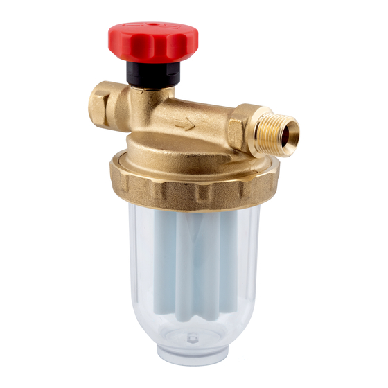
Transport und Lagerung Veränderungen am Produkt Führen Sie ausschließlich solche Arbeiten an und mit dem Produkt durch, die in dieser Betriebsanleitung beschrieben sind. Nehmen Sie keine Verände- rungen vor, die in dieser Betriebsanleitung nicht beschrieben sind. Transport und Lagerung Das Produkt kann durch unsachgemäßen Transport und Lagerung beschä- digt werden. - Page 6 Produktbeschreibung Produktbeschreibung Einstrangfilter Typ V 500 / V½ 500 Das Produkt besteht aus einem Messing-Filtergehäuse mit Anschlüssen G (Typ V½ 500 mit Anschlüssen G½), einem Filtereinsatz, einer transparenten Filtertasse sowie einem Absperrventil. Einstrangfilter Typ R 500 Das Produkt besteht aus einem Messing-Filtergehäuse mit Anschlüssen , einem Filtereinsatz, einer transparenten Filtertasse, einem Absperrven- til sowie einem Überströmventil.
- Page 7 Produktbeschreibung Abbildung 2: Typ R 500 Abbildung 3: Typ Z 500 / Z½ 500 Heizölfilter...
- Page 8 Produktbeschreibung Technische Daten V = Einstrangfilter R = Einstrangfilter mit Rücklaufzuführung = Zweistrangfilter ohne Kennzeichn. = Anschluss Tank/Brenner G ½ = Anschluss Tank/Brenner G½ = Zulässige Medien siehe 500 Optimum "Bestimmungsgemäße Verwendung" = Sinterkunststoffsieb 50-70 μm Si = Filzsieb...
- Page 9 Produktbeschreibung Durchfluss-Nennleistung Stahl Filz Siku Siku 100 µm 50-75 µm 50-70 µm 50-70 µm lang V 500 V½-500 R 500 Z 500 Z½-500 p Tabelle 1: Öldurchsatz in l/h bei = 100 mbar nach EN 12514-2 bei 50 %-igem Ver- schmutzungsgrad des Filtereinsatzes Heizölfilter Ausführung „Optimum“...
-
Page 10: Montage
Montage Montage HINWEIS AUSLAUFEN VON ÖL BEI FILTERWECHSEL • Stellen Sie sicher, dass die Druckversorgungsanlage spannungsfrei geschaltet ist. • Lassen Sie eventuell vorhandenen Vordruck ab. Nichtbeachtung dieser Anweisungen kann zu Sachschäden führen. Arbeiten an und mit diesem Produkt dürfen nur von Fachkräften eines Fach- betriebs nach AwSV vorgenommen werden. - Page 11 Montage Ist keine ausreichende Druckbeständigkeit an der Rücklaufseite der Brenner- pumpe vorhanden, empfehlen wir den Einsatz der automatischen Heizölent- lüfter Flow-Control oder der Filterentlüfter FloCo-Top. Produkt montieren Das Produkt wird vor dem Brenner installiert. Die Armatur kann über oder unter dem maximalen Tankfüllstand eingebaut werden. ...
- Page 12 Anzugsmoment beträgt 40 ±10 Nm. 2. Verwenden Sie für die Produkttypen V 500, R 500 und Z 500 eine AFRISO Universal-Rohrverschraubung (Zubehör). Das Anzugsmoment für Rohrverschraubungen ø 8 mm beträgt 15 ±5 Nm. Das Anzugsmo- ment für Rohrverschraubungen ø 10 mm beträgt 20 ±5 Nm. Die Monta- geanleitung liegt der Rohrverschraubung bei.
- Page 13 Montage A. Düsenverbrauch [l/h] B. Innendurchmesser der Saugleitung [mm] C. Fließgeschwindigkeit des Heizöls [m/s] D. Innendurchmesser < 4 mm nicht zulässig E. Empfohlener Bereich nach DIN 4755-2 Ø Abbildung 6: Nomogramm Beispiel: Bei einer Fördermenge von 20 l/h und einer mittleren Fließge- schwindigkeit von ungefähr 0,23 m/s wird eine Leitung mit Innendurchmes- ser 6 mm (Rohraußendurchmesser 8 x 1 mm) benötigt.
- Page 14 Inbetriebnahme Einsatz eines Antiheberventils Wenn der maximale Füllstand im Heizöltank höher als der tiefste Punkt der Saugleitung liegt, kann bei einer Undichtheit Heizöl durch Saugheberwirkung selbsttätig aus dem Heizöltank auslaufen. Als Sicherheitseinrichtung müs- sen Magnetventile, Membran-Antiheberventile oder Kolben-Antiheberventile eingesetzt werden. A.
-
Page 15: Betrieb
Betrieb Betrieb Druckbetrieb Beim Einsatz des Produkts im Druckbetrieb muss dieses auf eine Mes- sing-Filtertasse umgerüstet werden. Stellen Sie sicher, dass Sie für diese Anwendung geeignete Vorkehrun- gen treffen, die auch im Störfall (defekter Druckminderer) ein Überschrei- ten des maximal zulässigen Betriebsdrucks (beispielsweise über ein Überströmventil oder einen Druckschalter) verhindern. -
Page 16: Wartung
Wartung Wartung Wartungsintervalle HINWEIS UNGEEIGNETE REINIGUNGSMITTEL • Stellen Sie sicher, dass Sie bei der Reinigung der Kunststoffteile lösemittel- freie Reinigungsmittel verwenden. Nichtbeachtung dieser Anweisungen kann zu Sachschäden führen. Zeitpunkt Tätigkeit Bei Bedarf Reinigen Sie die Kunststoffteile mit einer wässri- gen Seifenlauge Jährlich oder bei Bedarf Ersetzen Sie den Filtereinsatz Alle 5 Jahre Ersetzen Sie die Brennerschläuche... - Page 17 Wartung Filtereinsatz tauschen 8.2.1 Filtereinsatz ausbauen Heizölfilter...
- Page 18 Wartung Heizölfilter...
- Page 19 Wartung 8.2.2 Filtereinsatz einbauen Heizölfilter...
-
Page 20: Fehlerbehebung
Störungsbeseitigung Störungsbeseitigung Störungen, die nicht durch die im Kapitel beschriebenen Maßnahmen besei- tigt werden können, dürfen nur durch den Hersteller oder Fachkräfte beho- ben werden. Problem Mögliche Ursache Fehlerbehebung Unregelmäßige Störab- A) Luftansammlungen A) Legen Sie die schaltungen des Bren- in Saugleitung durch zu Saugleitung korrekt aus ners... - Page 21 Ölentlüfters durch Brennerpumpe erzeugt Führen Sie eine Saug- kein ausreichendes druckprüfung an der Vakuum Pumpe durch. Die Pumpe muss mindes- tens einen Druck von -0,4 bar aufbauen Sonstige Störungen Bitte wenden Sie sich an die AFRISO-Service Hotline Heizölfilter...
-
Page 22: Außerbetriebnahme Und Entsorgung
2. Entsorgen Sie das Produkt. Rücksendung Vor einer Rücksendung Ihres Produkts müssen Sie sich mit uns in Verbin- dung setzen. Gewährleistung Informationen zur Gewährleistung finden Sie in unseren Allgemeinen Geschäftsbedingungen im Internet unter www.afriso.com oder in Ihrem Kauf- vertrag. Heizölfilter... -
Page 23: Ersatzteile Und Zubehör
Ersatzteile und Zubehör Ersatzteile und Zubehör HINWEIS UNGEEIGNETE TEILE • Verwenden Sie nur Original Ersatz- und Zubehörteile des Herstellers. Nichtbeachtung dieser Anweisung kann zu Sachschäden führen. Produkt Artikelbezeichnung Art.-Nr. Abbildung Einstrangfilter V 500 Si 20292 V 500 St 20294 Zweistrangfilter Z 500 Si 20429 Z 500 St... - Page 24 Ersatzteile und Zubehör Ersatzteile und Zubehör Artikelbezeichnung Art.-Nr. Abbildung Kolben-Antiheberventil KAV 20240 Membran-Antiheberventil MAV 20139 Filtertasse kurz (Typ 500) 20254 Kunststoff für Saugbetrieb Filtertasse lang (Typ Optimum) 20258 Kunststoff für Saugbetrieb Filtertasse (Typ 500) 20261 Messing für Druckbetrieb Überwurfmutter M64 x 1,5 Messing 10 11 050008 Filtertasse (Typ 500)...
- Page 25 Operating instructions Fuel oil filters Single line filters V, R Dual-line filter Z Copyright 2019 AFRISO-EURO-INDEX GmbH. All rights reserved. Lindenstraße 20 74363 Güglingen MVV TB Telephone+49 7135 102-0 C 2.15.23 Service+49 7135 102-211 EN 12514-2 Telefax +49 7135 102-147 info@afriso.com...
- Page 26 About these operating instructions About these operating instructions These operating instructions describe fuel oil filters (also referred to as "prod- uct" in these operating instructions). These operating instructions are part of the product. • You may only use the product if you have fully read and understood these operating instructions.
-
Page 27: Information On Safety
Information on safety Information on safety Safety messages and hazard categories These operating instructions contain safety messages to alert you to poten- tial hazards and risks. In addition to the instructions provided in these oper- ating instructions, you must comply with all directives, standards and safety regulations applicable at the installation site of the product. - Page 28 Information on safety In addition, perform a risk assessment in view of the planned application, according to an approved risk assessment method, and implement the appropriate safety measures, based on the results of the risk assessment. Take into account the consequences of installing or integrating the product into a system or a plant.
-
Page 29: Transport And Storage
Transport and storage Modifications to the product Only perform work on and with the product which is explicitly described in these operating instructions. Do not make any modifications to the product which are not described in these operating instructions. Transport and storage The product may be damaged as a result of improper transport or storage. -
Page 30: Product Description
Product description Product description Single-line filter type V 500 / V½ 500 The product consists of a brass filter housing with connections G (type V½ 500 with connections G½), a filter insert, a transparent filter cup and a shutoff-valve. Single line filter type R 500 The product consists of a brass filter housing with connections G , a filter insert, a transparent filter cup, a shutoff-valve and a bypass valve. - Page 31 Product description Fig. 2: Type R 500 Fig. 3: Type Z 500 / Z½ 500 Fuel oil filters...
- Page 32 Product description Technical data V = single-line filter R = single-line filter with return line supply = dual-line filter No designation = Connection tank/burner G 8 ½ = Connection tank/burner G½ = Approved media see 500 Optimum "Intended use" = Sintered plastic sieve 50-70 μm...
- Page 33 Product description Nominal flow rate Steel Felt Type Sintered Sintered plastic plastic 100 µm 50-75 µm 50-70 µm 50-70 µm long V 500 V½-500 R 500 Z 500 Z½-500 p Table 1: Oil flow rate in l/h with = 100 mbar as per EN 12514-2 at pollution degree of 50 % of filter insert Fuel oil filters version "Optimum"...
- Page 34 Mounting Mounting NOTICE ESCAPING OIL DURING FILTER REPLACEMENT • Verify that the pressure supply system is disconnected from mains. • Discharge any inlet pressure. Failure to follow these instructions can result in equipment damage. Preparing mounting of R 500 Verify that the burner pump has a sufficient pressure resistance at the return end (see "Return pressure").
- Page 35 Mounting Mounting the product Install the product upstream of the burner. The fitting can be installed above or below the maximum tank level. Verify that the permissible ambient temperature is not exceeded. Verify that the product is not mounted the product on top of or next to a non-insulated boiler part, above opening dampers at furnaces or to the flue gas pipe.
- Page 36 G as per DIN 3852. The tightening torque is 40 ±10 Nm. 2. Use an AFRISO universal screwed pipe connection (accessories) for product types V 500, R 500 and Z 500. The tightening torque for screwed pipe connections ø 8 mm is 15 ±5 Nm. The tightening torque for screwed pipe connections ø...
- Page 37 Mounting A. Nozzle consumption [l/h] B. Inside diameter of the suc- tion line [mm] C. Flow rate of the fuel oil [m/s] D. Inside diameter <4 mm not permissible E. Recommended range as per DIN 4755-2 Ø Fig. 6: Nomograph Example: A pipe with an inside diameter of 6 mm (outer pipe diameter 8 x 1 mm) is required for a volume of 20 l/h and an average flow rate of approximately 0.23 m/s.
- Page 38 Commissioning Use of an anti-siphon valve If the maximum level in the fuel oil tank is higher than the lowest point of the suction line, fuel oil can be siphoned out of the fuel oil tank in the case of a leak.
-
Page 39: Operation
Operation Operation Pressure mode If the product is used in pressure mode, the product must be used with a brass filter cup. In the case of such applications, take appropriate measures to keep the maximum permissible operating pressure from being exceeded even in the case of error conditions (defective pressure reducer), for example, by means of a bypass valve or a pressure switch, etc. -
Page 40: Maintenance
Maintenance Maintenance Maintenance intervals NOTICE UNSUITABLE CLEANING AGENTS • Verify that you use only cleaning agents which do not contain solvents for cleaning the plastic parts. Failure to follow these instructions can result in equipment damage. When Activity If required Clean the plastic parts with soap suds Annually or if required Replace the filter insert... - Page 41 Maintenance Replacing the filter insert 8.2.1 Dismounting the filter insert Fuel oil filters...
- Page 42 Maintenance Fuel oil filters...
- Page 43 Maintenance 8.2.2 Mounting the filter insert Fuel oil filters...
-
Page 44: Troubleshooting
Troubleshooting Troubleshooting Any malfunctions that cannot be removed by means of the measures described in this chapter may only be repaired by the manufacturer or by qualified persons. Problem Possible reason Repair Burner switches off at A) Air accumulations in A) Properly rate the suc- irregular intervals due to the suction line because... - Page 45 Burner pump does not Perform a suction test at generate a sufficient the pump. The pump vacuum must generate a pres- sure of at least -0.4 bar Other malfunctions Contact the AFRISO service hotline Fuel oil filters...
-
Page 46: Decommissioning / Disposal
1. Dismount the product (see chapter "Mounting", reverse sequence of steps). 2. Dispose of the product. Returning the device Get in touch with us before returning your product. Warranty See our terms and conditions at www.afriso.com or your purchase contract for information on warranty. Fuel oil filters... -
Page 47: Spare Parts And Accessories
Spare parts and accessories Spare parts and accessories NOTICE UNSUITABLE PARTS • Only use genuine spare parts and accessories provided by the manufac- turer. Failure to follow these instructions can result in equipment damage. Product Product designation Part no. Figure Single line filters V 500 Si 20292... - Page 48 Spare parts and accessories Spare parts and accessories Product designation Part no. Figure Piston type anti-siphon valve KAV 20240 Diaphragm type anti-siphon valve MAV 20139 Filter cup short (type 500) 20254 Plastic, for suction mode Filter cup long (type Optimum) 20258 Plastic, for suction mode Filter cup brass (type 500)...
- Page 49 Notice technique Filtre fuel Filtre monotube V, R Filtre à deux tubes Z Copyright 2019 AFRISO-EURO-INDEX GmbH. Tous droits réservés. Lindenstraße 20 74363 Güglingen MVV TB Téléphone +49 7135 102-0 C 2.15.23 Service +49 7135 102-211 EN 12514-2 Téléfax +49 7135 102-147 info@afriso.com...
- Page 50 La présente notice technique La présente notice technique Cette notice technique contient la description des filtres fuel (dénommé ci-après "produit"). Cette notice technique fait partie du produit. • Utilisez le produit seulement après que vous aurez lu et compris intégra- lement la notice technique.
-
Page 51: Informations Sur La Sécurité
Informations sur la sécurité Informations sur la sécurité Consignes de sécurité et classes de risques Cette notice technique contient des consignes de sécurité destinées à attirer l'attention sur les dangers et les risques. Outre les instructions contenues dans cette notice technique, il faut vous assurer de l'observation de tous les règlements, normes et consignes de sécurité... - Page 52 Informations sur la sécurité En outre effectuez une évaluation des risques portant sur l'application concrète que vous prévoyez à l'aide d'un procédé reconnu et prenez toutes les mesures de sécurité nécessaires correspondant au résultat. Prenez aussi en compte les conséquences possibles du montage ou de l'intégration du produit dans un système ou une installation.
-
Page 53: Transport Et Stockage
Transport et stockage Modification du produit En travaillant sur le produit et avec celui-ci, effectuez exclusivement les opé- rations décrites dans cette notice technique. N'effectuez pas de modifica- tions non décrites dans cette notice technique. Transport et stockage Un transport et un stockage inadéquats risquent de causer des dommages au produit. -
Page 54: Description Du Produit
Description du produit Description du produit Filtre monotube type V 500 / V½ 500 Le produit est composé d'un boîtier filtre en laiton avec raccords G (type V½ 500 avec raccords G½), d'un élément filtrant, d'un bol de filtre transpa- rent et d'une vanne d'arrêt. - Page 55 Description du produit Figure 2: Type R 500 Figure 3: Type Z 500 / Z½ 500 Filtre fuel...
- Page 56 Description du produit Caractéristiques techniques V = Filtre monotube R = Filtre monotube avec retour = Filtre à deux tubes Sans désign. = Raccordement réservoir/brû- ½ leur G 8 = Liquides approuvés voir 500 Optimum "Usage normal" = Tamis en matière plastique Siku 50-70 μm Si...
- Page 57 Description du produit Débit nominal Acier Feutre Siku Type Siku 100 µm 50-75 µm 50-70 µm 50-70 µm long V 500 V½-500 R 500 Z 500 Z½-500 p Tableau 1 : Débit fuel en l/h avec = 100 mbar selon EN 12514-2, dégrée d'encras- sement de l'élément filtrant de 50 % Les filtres fuel "Optimum"...
-
Page 58: Montage
Montage Montage AVIS ÉCOULEMENT DU FUEL PENDANT EL CHANGEMENT DU FILTRE • Assurez-vous que le système de production de pression n'est pas sous ten- sion. • Déchargez toute pression d'entrée. La non-observation de ces instructions peut causer des dommages maté- riels. - Page 59 Montage Montage du produit Le produit est à installer en amont du brûleur. L'unité peut être montée au-dessus ou en dessous du niveau maximal du réservoir. Assurez-vous que la température ambiante autorisée n'est pas dépas- sée. Évitez tout montage du produit sur une partie non isolée de la chaudière ou à...
- Page 60 G1/2 selon DIN 3852. Le couple de serrage est de 40 ±10 Nm. 2. Utilisez un raccord tube universel AFRISO (accessoire) pour les types de produit V 500, R 500 et Z 500. Le couple de serrage pour un raccord tube ø...
- Page 61 Montage A. Consommation du gicleur [l/h] B. Diamètre intérieur de la conduite d'aspiration [mm] C. Vitesse d'écoulement du fuel [m/s] D. Diamètre intérieur < 4 mm inadmissible E. Plage recommandée selon DIN 4755-2 Ø Figure 6: Nomogramme Exemple : Pour un débit de 20 l/h et une vitesse d'écoulement moyenne de 0,23 m/s, il faut installer une conduite de diamètre interne de 6 mm (diamètre externe de 8 x 1 mm).
-
Page 62: Mise En Service
Mise en service Utilisation d'une valve anti-siphon Si le niveau de fuel maximum dans le réservoir est plus élevé que le point le plus bas de la conduite d'aspiration, il y a, en cas de fuite, un risque d'écou- lement (siphonnage) du fuel du réservoir. Des électrovannes, des valves anti-siphon à... - Page 63 Service Service Mode pression Si le produit est utilisé en mode pression, le produit doit être utilisé avec un bol de filtre en laiton. Pour cette application prenez des précautions appropriées (pressostat, soupape de décharge, etc.) ; en cas d'incident (réducteur de pression défectueux, etc.), la pression d'alimentation ne doit pas excéder la valeur admissible.
-
Page 64: Maintenance
Maintenance Maintenance Intervalles de maintenance AVIS NETTOYANTS INADAPTÉS • Utilisez uniquement des nettoyants sans solvant pour nettoyer les pièces en plastique. La non-observation de ces instructions peut causer des dommages maté- riels. Quand Opération Si nécessaire Nettoyez les parties plastiques avec mousse de savon Annuellement ou si Remplacez l'élément filtrant... - Page 65 Maintenance Replacer l'élément filtrant 8.2.1 Démontage d'élément filtrant Filtre fuel...
- Page 66 Maintenance Filtre fuel...
- Page 67 Maintenance 8.2.2 Montage d'élément filtrant Filtre fuel...
-
Page 68: Suppression Des Dérangements
Suppression des dérangements Suppression des dérangements Les dérangements ne figurant pas dans les mesures décrites dans ce cha- pitre doivent être éliminés uniquement par le fabricant ou par des personnes qualifiées. Problème Cause possible Action corrective Arrêts intempestifs et A) Accumulation d'air A) Utilisez un tube aléatoires du brûleur dans la conduite d'aspi-... - Page 69 La pompe du brûleur ne Effectuez un essai crée pas une dépres- d'aspiration de la sion suffisante pompe. La pompe doit générer une pression de -0,4 bar au moins Autre dérangement Veuillez contacter l'AFRISO Service Hot- line Filtre fuel...
-
Page 70: Mise Hors Service Et Élimination
2. Éliminez le produit. Retour Avant de retourner le produit, il faut que vous preniez contact avec nous. Garantie Les informations sur la garantie figurent dans nos "Conditions générales de vente" sur le site www.afriso.com ou dans votre contrat d'achat. Filtre fuel... -
Page 71: Pièces Détachées Et Accessoires
Pièces détachées et accessoires Pièces détachées et accessoires AVIS PIÈCES INADAPTÉES • N'utilisez que des accessoires et des pièces détachées d'origine provenant du fabricant. La non-observation de ces instructions peut causer des dommages maté- riels. Produit Désignation de l'article Référence Figure Filtre monotube V 500 Si 20292... - Page 72 Pièces détachées et accessoires Pièces détachées et accessoires Désignation de l'article Référence Figure Valve anti-siphon à piston KAV 20240 Valve anti-siphon à membrane MAV 20139 Bol de filtre court (type 500) 20254 Matière plastique pour mode aspiration Bol de filtre long (type Optimum) 20258 Matière plastique pour mode aspiration Bol de filtre (type 500)...
Need help?
Do you have a question about the Single line V Series and is the answer not in the manual?
Questions and answers