Advertisement
Quick Links
Advertisement

Subscribe to Our Youtube Channel
Related Manuals for FAAC T-MODE TM 35 ER


Summary of Contents for FAAC T-MODE TM 35 ER
- Page 1 T-MODE TM 35 ER - TM35 ERO TM 45 ER - TM 58 ER...
-
Page 2: Declaration Of Conformity
DECLARATION OF CONFORMITY Manufacturer: FAAC S.p.A. Address: Via Calari, 1 - 40069 Zola Predosa BOLOGNA - ITALY Declares that: Operator mod. TM 35 ER , TM35 ERO, TM 45 ER , TM 58 ER • conforms to the essential requirements of the following EEC directives: - 2006/95/EEC - 2004/108/EEC - 99/05/EEC • it thus conforms to the following harmonised standards:... -
Page 3: Technical Specifications
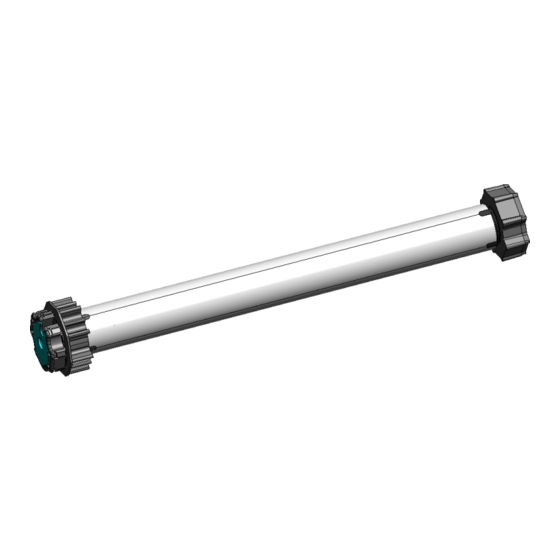
T-MODE TUBULAR MOTORS WITH RADIO ELECTRONIC TRAVEL LIMITS DESCRIPTION a Tubular motor b Example of wheel adapter. (Accessory) c Example of crown adapter. (Accessory) d Travel limit ring nut e Example of motor support (Accessory) f Mechanical sensor for obstacle detection (Accessory) Fig. 1 TECHNICAL SPECIFICATIONS USING THE MECHANICAL SENSOR FOR OBSTACLE DETECTION, THE “L” LENGTH OF THE MOTOR WITH THE ADAPTER INCREASES BY 41 mm ( L + 41 mm ) T-MODE TORQUE... - Page 4 MAX. MOTOR MOTOR “L” LENGTH WITH MODEL TORQUE FREQUENCY TIME SPEED VOLTAGE FREQUENCY POWER CURRENT SHAFT MAX. DIAMETER ADAPTER PROTECTION T-MODE (Nm) OF USE OF USE (Rpm) (Hz) ROTATIONS (mm) (mm) CLASS (min.) 58 ER 70/12 IP44 80/12 IP44 100/12 IP44 120/12 IP44 1) Measure dimension A on the tubular motor, as shown INSTALLATION in figure 3 ref. a. 3.1 ASSEMBLING THE TUBULAR MOTOR 2) Drill a hole with a drill Ø 3 mm on the roller (Fig.3 ref.
- Page 5 3.3 ELECTRIC CONNECTIONS 1) Cut power supply before attempting any job on the system. 2) Install an omnipolar switch with contact opening distance of 3 mm or greater on the power supply mains of the automated system. 3) Wire the cables according to the diagram; if the motor rotates in the opposite direction, do not reverse the black and brown wires, as at the end of the set-up, the up or down push-buttons are automatically matched to the correct direction of motor rotation.
- Page 6 4 MEMORY STORING THE FIRST RADIO Portable remote control REAR STOP / VIEW PREFERRED POSITION DOWN CHANGE RADIO CHANNEL PROGRAMMING ENABLE DISABLE PUSH-BUTTON SUN SENSOR Wall-mounted remote control Fig.8 MAX. 20 RADIO DEVICES CAN BE STORED IN THE MEMORY OF THE MOTOR INTERNAL RECEIVER (WALL-MOUNTED REMOTE CONTROLS, RADIO ANEMOMETERS, ETC.).
- Page 7 1) DURING THE MEMORY STORING OF THE FIRST REMOTE CONTROL AND TILL THE END OF THE SET-UP PROCEDURE OF THE TRAVEL LIMITS, THE MOTOR OPERATES IN DEAD-MAN MODE. (PUSH-BUTTON HELD DOWN) 2) BEFORE COMPLETING THE SET-UP , THE MOTOR COULD ROTATE IN THE OPPOSITE DIRECTION TO THE GIVEN COMMAND (E.G.: YOU PRESS THE UP PUSH-BUTTON AND THE ROLLING SHUTTER LOWERS) ;...
- Page 8 BEFORE COMPLETING THE SET-UP , THE MOTOR COULD ROTATE IN THE OPPOSITE DIRECTION TO THE GIVEN COMMAND (E.G. YOU PRESS THE UP PUSH-BUTTON AND THE ROLLING SHUTTER LOWERS); AT THE END OF THE SET-UP , THE UP AND DOWN PUSH-BUTTONS ARE AUTOMATICALLY MATCHED TO THE CORRECT DIRECTION OF ROTATION.
- Page 9 FIND THE PUSH-BUTTON CONTROLLING THE RISE, AND HOLD IT DOWN WITHOUT RELEASING IT UNTIL REACHING THE REQUIRED DOWN TRAVEL LIMIT POSITION. PRESS THE STOP / PREFERRED POSITION PUSH-BUTTON TO CONFIRM THE POSITION UNTIL THE MOTOR PERFORMS THE INDICATED MOVEMENTS DOWN TRAVEL LIMIT Fig.12 5.2.3 MANUAL SET-UP FOR ROLLING SHUTTERS...
- Page 10 PRESS THE STOP/PREFERRED POSITION PUSH-BUTTON FOR 2 SECONDS. RELEASE IT FOR 1 SECOND AND HOLD IT DOWN AGAIN TILL THE END OF THE INDICATED MOVEMENTS TO CONFIRM THE PERFORMED MEMORY STORING OF THE UP TRAVEL LIMIT. 1 second 2 seconds WITHIN 3 SECONDS PRESS THE UP OR DOWN PUSH-BUTTON AND TAKE THE ROLLING SHUTTER TO THE DOWN TRAVEL LIMIT DOWN...
- Page 11 5.2.3.2 MANUAL SET-UP FOR ROLLING SHUTTERS STARTING FROM THE DOWN TRAVEL LIMIT 1) Press the up or down push-button and take the rolling shutter to the selected position for the DOWN travel limit. Release the push-button. 2) Press the stop/preferred position push-button until the motor performs a brief movement in both directions. 3) Press the push-button controlling the rise and go to the up travel limit. 4) Press the stop/preferred position push-button for 2 seconds. Release it for 1 second and hold it down until the motor performs a brief movement in both directions to check the correct setting of both the rolling shutter mode and the down travel limit.
- Page 12 PRESS THE STOP/PREFERRED POSITION PUSH-BUTTON FOR 2 seconds. RELEASE IT FOR 1 SECOND AND HOLD IT DOWN AGAIN TILL THE END OF THE INDICATED MOVEMENTS TO CONFIRM THE PERFORMED MEMORY STORING OF THE UP TRAVEL LIMIT. 1 second 2 seconds WITHIN 3 SECONDS SET-UP FOR STANDARD AWNINGS, SPRING-TYPE OR FALL-TYPE 5.3.1 SET-UP FOR STANDARD AWNINGS, SPRING-TYPE OR FALL-TYPE, STARTING FROM THE UP TRAVEL LIMIT...
- Page 13 PRESS THE STOP/PREFERRED POSITION PUSH-BUTTON FOR 2 SECONDS. RELEASE IT FOR 1 SECOND AND HOLD IT DOWN AGAIN TILL THE END OF THE INDICATED MOVEMENTS TO CONFIRM THE PERFORMED MEMORY STORING OF THE UP TRAVEL LIMIT. Every pressing 1 second 2 seconds WITHIN 3 SECONDS PRESS THE UP OR DOWN PUSH-BUTTON AND TAKE THE AWINING TO THE...
- Page 14 PRESS THE UP OR DOWN PUSH-BUTTON AND TAKE THE AWINING TO THE DOWN TRAVEL LIMIT DOWN TRAVEL LIMIT HOLD DOWN THE STOP/PREFERRED POSITION PUSH-BUTTON TILL THE INDICATED MOVEMENTS PRESS THE UP OR DOWN PUSH-BUTTON AND TAKE THE AWINING TO THE UP TRAVEL LIMIT TRAVEL LIMIT PRESS TWICE THE STOP/PREFERRED POSITION PUSH-BUTTON FOR 2 SECONDS.
- Page 15 SET-UP FOR CASSETTE AWNING 5.4.1 SET-UP FOR CASSETTE AWNING STARTING FROM THE UP TRAVEL LIMIT BEFORE COMPLETING THE SET-UP , THE MOTOR COULD ROTATE IN THE OPPOSITE DIRECTION TO THE GIVEN COMMAND (E.G.: YOU SEND A RISE PULSE FROM THE REMOTE CONTROL AND THE AWNING LOWERS) ; AT THE END OF THE SET-UP , THE UP AND DOWN PUSH-BUTTONS ARE AUTOMATICALLY MATCHED TO THE CORRECT DIRECTION OF ROTATION.
- Page 16 DOWN TRAVEL LIMIT HOLD DOWN THE STOP/PREFERRED POSITION PUSH-BUTTON TILL THE INDICATED MOVEMENTS 5.4.2 SET-UP FOR CASSETTE AWNINGS STARTING FROM THE DOWN TRAVEL LIMIT 1) Press the up or down push-button and take the awning to the selected position for the DOWN travel limit. Release the push-button 2) Press the stop/preferred position push-button until the motor performs a brief movement in both directions. 3) Press the push-button controlling the rise and go to the up travel limit. 4) Press 3 times the stop/preferred position push-button, release it for 1 second and hold it down again until the motor performs a brief movement in both directions to check the correct setting of both the cassette awning mode and the up travel limit.
- Page 17 HOLD DOWN THE STOP/PREFERRED POSITION PUSH-BUTTON TILL THE INDICATED MOVEMENTS PRESS THE UP OR DOWN PUSH-BUTTON AND TAKE THE AWINING TO THE UP TRAVEL LIMIT TRAVEL LIMIT PRESS 3 TIMES THE STOP/PREFERRED POSITION PUSH-BUTTON, RELEASE IT FOR 1 SECOND AND HOLD IT DOWN AGAIN UNTIL THE END OF THE INDICATED MOVEMENTS TO CONFIRM THE PERFORMED MEMORY STORING OF THE UP TRAVEL LIMIT.
- Page 18 ADDING FURTHER REMOTE CONTROLS 1) Supply power to the motor. 2) On an already memory-stored remote control, press the PROGRAMMING push-button for 2 seconds and, within 5 seconds, press the STOP/PREFERRED POSITION push-button. 3) On the remote control to be memory stored, press the STOP/PREFERRED POSITION push-button within 5 seconds. 4) The motor performs two brief movements in both directions to confirm the performed memory storing of the remote control. REMOTE CONTROL ALREADY MEMORY STORED 2 seconds 2 seconds WITHIN 5 SECONDS REMOTE CONTROL TO MEMORY STORE RADIO DELETING DELETING A SINGLE REMOTE CONTROL 1) Press twice the programming push-button for 2 seconds 2) Within 10 seconds press the STOP/PREFERRED POSITION push-button for 2 seconds. 3) The motor performs a brief movement in both directions to confirm the performed deletion of the remote control. Every pressing 2 seconds WITHIN 10 SECONDS 2 seconds...
- Page 19 TOTAL DELETION OF THE RECEIVER (the set travel limits are not deleted) 1) Cut power to the motor, wait for 10 seconds and connect the red (or black) wire to the brown wire. (If a “step-by-step” push-button is available, just hold it down without making the connection.) 2) Supply power to the motor, after approx. 10 seconds the motor operates in both directions for 1 second signalling that the memory has been completely deleted. 3) Cut power again to the motor. Disconnect the red (or black) and the brown wires. (Release the push-button if the “step-by-step” push-button is available) 230 V ~ Press BROWN RED OR BLACK RED OR BLACK BROWN 230 V ~ BROWN RED OR BLACK RED OR BLACK BROWN...
-
Page 20: Advanced Menu
ADVANCED MENU THE ADVANCED MENU CAN ONLY BE ACCESSED AFTER HAVING SET THE TRAVEL LIMITS. THIS MENU ENABLES YOU TO MODIFY THE OBSTACLE DETECTION SENSITIVITY AND THE TORQUE IN THE LAST CENTIMETRES BEFORE THE UP TRAVEL LIMIT AND TO DEFINE A HIGH SENSITIVITY AREA FOR THE DETECTION OF BLOCKS WHEN RISING. - Page 21 9.2 DETECTING ICE ON THE GUIDES AND FITTED BOLTS DURING THE ROLLING SHUTTER RISE The T-MODE motor with electronic travel limit is able to detect possible bolts fitted in the rolling shutter as well as the presence of ice on the guides during the whole travel of the rolling shutter.
- Page 22 every pressing seconds 2 seconds WITHIN 1 SECOND The motor performs three brief movements to confirm you have entered the advanced menu Press twice the STOP/PREFERRED POSITION push-button (every pressing 2 seconds) and within 1 second press the STOP/PREFERRED POSITION push-button for 5 seconds to confirm the performed setting. STANDARD SENSITIVITY AREA HIGH SENSITIVITY AREA The motor performs two brief movements in both directions to confirm the performed setting of the torque and the...
- Page 23 Every pressing 2 seconds 4 seconds Every pressing 2 seconds WITHIN 1 SECOND x N times 1 Pressing of down push-button = Obstacle detection not active ..2,3,4,5,6,7,8,9 Pressings of down push-button 9 Pressing of down push-button = Maximum obstacle detection sensitivity 9.3.2 MODIFYING THE POSITION OF OBSTACLE DETECTION END You can modify the position of the obstacle detection end.
-
Page 24: Troubleshooting
5 seconds OBSTACLE DETECTION AREA DETECTION END AREA 10 PREFERRED POSITION 10.1 MEMORY-STORING THE PREFERRED POSITION A P R E F E R R E D P O S I T I O N C A N B E D E F I N E D O N T H E R O L L I N G S H U T T E R . T H I S P O S I T I O N C A N ONLY BE REACHED WHEN THE MOTOR IS AT REST BY PRESSING THE STOP/PREFERRED POSITION PUSH-BUTTON. - Page 25 BEHAVIOUR REASON SOLUTION ON ACTIVATION, THE MOTOR DOES NOT If you wish to modify the travel limits, execute a reset PERFORM ANY MOVEMENT as indicated in chapter 6 and perform a new learning Travel limits already set operation (chpt.5) Sun sensor Disable the sun sensor activated On the remote control, perform the memory storing procedure for the first remote control THE MOTOR HAS TRAVEL LIMITS ALREADY If there are not other remote controls, perform total deletion of the memory and the memory storing operation of the SET, BUT IT DOES NOT ACCEPT COMMANDS...
- Page 26 +33 4 72218700 tel. +1 904 4488952 tel. +971 42146733 www.faac.fr www.faacusa.com www.faac.ae FAAC FRANCE - AGENCE PARIS FAAC INTERNATIONAL INC Massy - Paris, France Fullerton, California - U.S.A. tel. +33 1 69191620 tel. +1 714 446 9800 www.faac.fr www.faacusa.com...
Need help?
Do you have a question about the T-MODE TM 35 ER and is the answer not in the manual?
Questions and answers