Table of Contents
Advertisement
Quick Links
MODELS APLR - APOLLO 6-DIGIT RATE INDICATOR [TIME BASE] AND
PBLR - 4/6 DIGIT MODULE FOR USE WITH THE LARGE DIGIT DISPLAY (LDD)
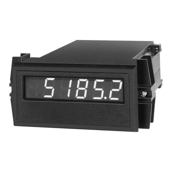
6-DIGIT, 0.56" (14.2 mm) HIGH LED DISPLAY (APLR)
CRYSTAL-CONTROLLED TIME-BASE PROGRAMMABLE UP TO
32.764 SECONDS PROVIDES DIRECT-READING FOR ANY RATE
UNITS
0.02% ACCURACY
PROGRAMMABLE DECIMAL POINTS
FREQUENCY DOUBLING
PROGRAMMABLE INPUT CIRCUIT, ACCEPTS OUTPUTS FROM
A WIDE VARIETY OF SENSORS
LEADING ZERO BLANKING
POWER-UP SELF-TEST
NEMA 4/IP65 SEALED FRONT METAL BEZEL
DESCRIPTION
The Apollo Time Base Rate Indicators (Model APLR) and Module (Model
PBLR), provide the versatility and flexibility needed to accommodate virtually
any rate measuring need. Based on Micro-processor technology, this unit
represents the optimum in cost/performance ratio.
This unit has the ability to scale for direct readout in terms of the units being
measured. Whether a machine produces bottles, cloth, wire, or beverage mix,
operation is enhanced when the rate readout is expressed directly in
bottles/min., feet/min., gallons/hour, or whatever units are needed in plant
operations. The APLR/PBLR can provide this capability through its settable
time base, programmable decimal points, and frequency doubling functions.
The APLR/PBLR can also accommodate magnetic pickups, as well as logic
(sourcing output) sensors and NPN open collector (sinking output) sensors.
This unit also has a self-test feature, which checks all the micro-processor
and display driver circuitry after power-up (if enabled). This self-test also can
be used to test the time base select DIP switches and decimal point select DIP
switches, to make certain all switches are functioning properly.
Power and input connections are made via a removable terminal block,
located at the rear of the unit. Each terminal can accept one #14 AWG wire. DIP
switches at the side of the unit are used to program the input configuration.
The Apollo Rate Indicator has a sealed metal die-cast bezel which meets
NEMA 4/IP65 specifications for wash-down and/or dust, when properly
installed. Two mounting clips are provided for easy installation. The Time Base
Rate Indicator uses a 6-digit, 0.56" (14.2 mm) high LED display, which is
readable to 23 feet (7 M).
CAUTION: Risk of Danger.
Read complete instructions prior to
installation and operation of the unit.
DIMENSIONS In inches (mm)
CAUTION: Risk of electric shock.
Note: Recommended minimum clearance (behind the panel) for
mounting clip installation is 2.1" (53.4) H x 5.5" (140) W.
SAFETY SUMMARY
All safety related regulations, local codes and instructions that appear in the
manual or on equipment must be observed to ensure personal safety and to
prevent damage to either the instrument or equipment connected to it. If
equipment is used in a manner not specified by the manufacturer, the protection
provided by the equipment may be impaired.
SPECIFICATIONS
1. DISPLAY: 6-Digit, 0.56" (14.2 mm) high LED display. (APLR)
2. POWER REQUIREMENTS:
APLR
AC Operation: Available in two voltages.
115 VAC, ±10%, 50/60 Hz, 14 VA or
230 VAC, ±10%, 50/60 Hz, 14 VA
DC Operation:
24 VDC, 10% @ 0.6 A max.
Note: All available units can be powered at Terminal #3 from a 11 to 14
VDC, 0.6 A max. power supply.
PBLR
AC Operation: Switch selected via the LDD power supply board,
115/230 (+/-10%), 50/60 Hz, 10 VA for 4-digit, 15 VA for 6 digit
(including LDD).
3. SENSOR POWER: +12 VDC, ±25% @ 100 mA max.
4. MAXIMUM OPERATING FREQUENCY: 10 KHz, 50% duty cycle.
10,000 cps with min. pulse width "ON" and "OFF" times of 50 µsec.
5. TIME BASE SELECTION RANGE: 0.004 to 32.764 seconds.
6. ACCURACY: 0.02%
7. MAXIMUM INPUT VOLTAGE AND CURRENT: When the "SIG. IN"
(Terminal 5) is driven from external signal voltages, max. voltage swing is
±50 V peak. Input voltage can be dropped by an external series resistance that
limits input current to ±5 mA. (These ratings are for S3 "OFF".)
1
Bulletin No. APLR-N
Drawing No. LP0118
Released 6/06
PANEL CUT-OUT
Advertisement
Table of Contents

Related Manuals for red lion APLR Series


Summary of Contents for red lion APLR Series
- Page 1 Bulletin No. APLR-N Drawing No. LP0118 Released 6/06 MODELS APLR - APOLLO 6-DIGIT RATE INDICATOR [TIME BASE] AND PBLR - 4/6 DIGIT MODULE FOR USE WITH THE LARGE DIGIT DISPLAY (LDD) 6-DIGIT, 0.56" (14.2 mm) HIGH LED DISPLAY (APLR) CRYSTAL-CONTROLLED TIME-BASE PROGRAMMABLE UP TO 32.764 SECONDS PROVIDES DIRECT-READING FOR ANY RATE UNITS 0.02% ACCURACY...
-
Page 2: Electromagnetic Compatibility
SPECIFICATIONS (Con’t) INPUT SET-UP 8. INPUT IMPEDANCE: With S1 and S3 “OFF”, the resistive input The selection of input set-up is accomplished by the first three of six DIP impedance exceeds 1megohm as long as the “SIG. IN” (Terminal 5) input switches, located along the side of the unit. -
Page 3: Emc Installation Guidelines
WIRING CONNECTIONS The next portion of self-test will display four groups of zeros and/or ones. (The first two digits from the left, in each group, will always show a zero.) In As depicted in the drawing showing the rear view of the Apollo Rate the first group, the third digit represents the 13th (X4096) DIP switch setting. -
Page 4: Installation Environment
CONNECTIONS & CONFIGURATION SWITCH SET-UP FOR VARIOUS SENSOR OUTPUTS COUNT SWITCH OR ISOLATED TRANSISTOR OUTPUTS SENSORS WITH CURRENT SINK OUTPUT (NPN O.C.) [Includes ASTC, LMPC, PSAC, RPGC, (RPGB, RPGH) * , LSC] RECOMMENDED RULES FOR MAGNETIC PICKUP CONNECTIONS SENSORS WITH CURRENT SOURCE OUTPUT (PNP O.C.) 1. - Page 5 TIME BASE SETTING PROCEDURE FLOW RATE INDICATION APPLICATION The Apollo Time Base Rate Indicator has a time base selection range of A positive displacement pump is driven by a gear reducer and an AC motor. 0.004 sec. to 32.764 sec. For a minimum time base (0.004 sec.), the X1 DIP An ARCJ NEMA C FLANGE is mounted to the end of this AC motor.
-
Page 6: Troubleshooting
WEB SPEED INDICATION APPLICATION A newspaper publishing company wants to know the rate at which their printing press is operating. A fifty-tooth timing sprocket is mounted to the shaft of one of the press rollers. An MP-62TA magnetic pickup is used to sense the moving teeth. - Page 7 This page intentionally left blank...
-
Page 8: Limited Warranty
The Company disclaims all liability for any affirmation, promise or representation with respect to the products. The customer agrees to hold Red Lion Controls harmless from, defend, and indemnify RLC against damages, claims, and expenses arising out of subsequent sales of RLC products or products...
Need help?
Do you have a question about the APLR Series and is the answer not in the manual?
Questions and answers