
Related Manuals for astrojolo AstroLink 4 Pi

Summary of Contents for astrojolo AstroLink 4 Pi
- Page 1 AstroLink 4 Pi manual - astrojolo.com AstroLink 4 Pi astrojolo.com @2021 Rev. 1.0...
-
Page 2: Main Features
• DS1820 temperature sensor input • Real-time clock embedded (AstroLink 4 Pi version 2 only) • permanent focuser position – no need to park focuser after the session • 2 adjustable PWM power outputs to control dew heaters, telescope fans, or custom Peltier coolers. -
Page 3: Device Overview
AstroLink 4 Pi requires a Raspberry Pi 4 module to be installed. Module with 4GB of RAM is recommended. AstroLink 4 Pi has been designed to work under the control of the dedicated AstroLink 4 Pi INDI driver, which is available at https://github.com/astrojolo/astrolink4pi... -
Page 4: External View
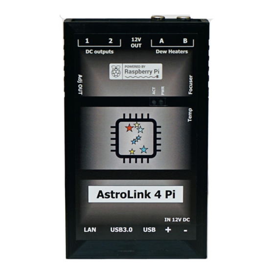
AstroLink 4 Pi manual - astrojolo.com External view Figure 1 - external views 1. LAN port 6. Regulated RCA outputs 2. USB3.0 ports 7. 12V DC output (non-switchable) 3. USB2.0 ports 8. Switchable 12V outputs 4. XT60 power input (12V DC) 9. -
Page 5: Version Comparison
RTC battery replacement (AstroLink Pi 4 version 2 only) AstroLink 4 Pi revision (version) is displayed in the log window after clicking Connect button CR2032 battery that is used to sustain real-time clock should work several years. If you notice that after switching on the device time is not set properly it may indicate that battery needs replacement. -
Page 6: Hardware Setup
Figure 2 - enclosure screws Installing the Raspberry Pi module requires opening the AstroLink 4 Pi enclosure. You need to unscrew four out of eight screws at the device's sides. Please remove only bottom screws. Then remove enclosure top. After that, you need to unplug the cooling fan. -
Page 7: Setting Focusing Motor Current
Setting focusing motor current Figure 4 - AstroLink 4 Pi interior AstroLink 4 Pi revision (version) is displayed in the log window after clicking Connect button. Version 1 only The stepper motor current is regulated with a small potentiometer at the stepper motor controller (see Figure 4). -
Page 8: Setting The Regulated Output Voltage
– it should be left in the default factory position 0.2V. The stepper motor socket pinout is presented in Figure 5. Figure 5 - AstroLink 4 Pi focusing motor output Required connections are listed in the table below. -
Page 9: Connecting Temperature Sensor
The required connections between the DS1820 sensor and jack 3.5mm plug are presented below: DS1820 Jack 3.5mm Sleeve DQ (data) Ring The temperature sensor needs to be connected to AstroLink 4 Pi before the power is on. It will not be recognized otherwise. Rev. 1.0... -
Page 10: Software Installation
The recommended setting is 60-70C – to be on the safe side. When the CPU reaches that temperature the cooling fan will be switched on. All these actions above are not required when you purchase AstroLink 4 Pi device with the preconfigured system. -
Page 11: Indi Driver Configuration
You can install the drivers by running: sudo make install Real-Time clock enabling - only version 2 To enable automatic synchronization of the RTC embedded in version 2 of AstroLink 4 Pi you need to edit the file sudo nano /etc/rc.local and add the following line before exit 0 statement at the file end echo ds1307 0x68 >... -
Page 12: Main Control
Telescope device data (aperture and focal length). If the temperature sensor is connected to AstroLink 4 Pi device, then the Temperature section is present and the current temperature is displayed here. When temperature reading is available, also temperature compensation is possible. -
Page 13: Options
For 12V geared unipolar motors set 350 or 400mA here. Stepper current in version 1 of AstroLink 4 Pi must be set with the potentiometer (see Hardware setup) Snoop device – that is telescope device name that will be used to retrieve aperture and focal length data. -
Page 14: Focuser
AstroLink 4 Pi manual - astrojolo.com Temperature coefficient – when the temperature sensor is available, temperature compensation may be performed. The number of steps per one degree of the temperature change should be entered into this field. Temperature compensate – enable or disable temperature compensation. The temperature compensation cycle is 30 seconds. -
Page 15: System
AstroLink 4 Pi manual - astrojolo.com System Figure 10- System tab This tab contains several read-only fields with some information about the system. System Ctrl section allows to reboot or turn off the operating system, but to use these buttons some additional configuration of sudo is required, so these operations are allowed without a password. -
Page 16: Outputs
DC 12V outputs in the device. One is permanent, and two are switchable and can be controlled in this panel. There are also two RCA sockets in the AstroLink 4 Pi that can be used for powering dew cap heaters. -
Page 17: Temperature Compensation
AstroLink 4 Pi manual - astrojolo.com Temperature compensation Temperature compensation in AstroLink 4 Pi is implemented linearly. So there is only one parameter that describes how temperature affects the focus point. It is not a perfect approach, however, its accuracy is good enough for most amateur setups. -
Page 18: Ground Loops
AstroLink 4 Pi manual - astrojolo.com Ground loops The ground loop in the electrical system occurs when two points that should have the same potential have different voltages. The ground loop in the astroimaging setup may occur when the ground (i.e. minus of power supply voltage) is connected to one receiver with more than one cable path. - Page 19 WiFi network, then it will start as a failover with its WiFi hotspot: SSID astroberry, password astroberry, IP 10.42.0.1. If all above fails, then switch off the home router, so there is no WiFi around, and restart AstroLink 4 Pi. After about two minutes it should be astroberry WiFi available, where you can connect.
-
Page 20: Table Of Contents
AstroLink 4 Pi manual - astrojolo.com Table of contents Main features: ..............................2 Technical data ..............................2 Device overview ..............................3 System and hardware requirements ....................... 3 PWM outputs ..............................3 Switchable 12V DC outputs ..........................3 Focusing motors control ..........................3 Permanent 12V DC output .......................... - Page 21 AstroLink 4 Pi manual - astrojolo.com Scenario two ..............................18 Tips and troubleshooting ........................... 19 Rev. 1.0...
Need help?
Do you have a question about the AstroLink 4 Pi and is the answer not in the manual?
Questions and answers