Advertisement
INSTALLATION
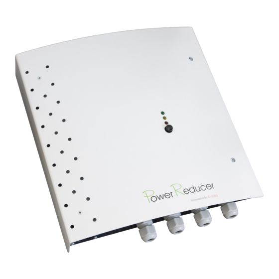
1) Fix Power Reducer onto the wall.
a) Remove the cover unwscrewing the 4 screws on the front of Power Reducer.
b) Drill the wall according to the 4 holes at the back of the device.
c) Securely mount the device on the wall using appropriate screws
!
Warning: do not use Power Reducer itself as a template for drilling holes directly on
the wall.
MIN 7 cm
MIN 7 cm
LOCATION: install Power Reducer next to the wire that supplies power to the resisitive load
(immersion). They will share the same power supply!
VENTILATION: install the device vertically (cable glands must be placed DOWNWARDS).
Proper ventilation is also guaranteed by clearings around the device. Make sure no other ob-
jects are placed within a range of 7 centimeteres.
2) Install the Current Transformer
a) connect the Current Transformer to the Power Reducer terminals
1 2
b) position the Current Transformer
I) Identify the live-phase cable related to the
I) Identificare il cavo di FASE di SCAMBIO
II) Clamp the CT over the "Exchange" (GRID)
electricity exchange with the GRID
live-phase cable
Mains meter
Generation
Scambio
Produzione
towards the
(GRID)
(rete ENEL)
mains meter
Utenza
Household
WARNING: pay ATTENTION that CT is actually orientated in the right direction and that it clamps
the Live-phase wire that connects the RESIDUAL CURRENT CIRCUIT-BREAKER to the Mains
meter (GRID). Make sure the Current Transformer is NOT clamped on the Live-phase that con-
nects the residual curent circuit-braker to the household.
Pag 5
3) Cut the resistive load power supply cable and connect the pins
to the correct terminals.
WARNING: before cutting the cable, make sure the power to the immersion is OFF
towards the immersion
Possible measurements made with amperometric clamps must be detected on the Live-phase
that connects the power source with the Power Reducer. Measurements detected on the wire
directed towards the resistive load will be inaccurate.
Power Supply cables must be tripolar. Each single wire must feature a minimum
dimension of 2.5 mm
Installation of 16 A thermal magnetic to protect the device
4) Switch on Power Reducer and verify the correct operation mode
LED behaviour
GREEN LED flashing:
> frequency > energy read by CT
YELLOW LED flashing:
> frequency > energy to immersion
RED LED is OFF
GREEN LED is steady ON
Terminal 2
Power Reducer
YELLOW LED is OFF
RED LED is OFF
GREEN LED is steady ON
YELLOW LED is OFF
L1
RED LED blinks quickly 3 times
green point
alongside 3 quick beeps
towards the
residual current
5) Wire the clean contact for system bypass switch (optional)
circuit-breaker
When the Clean Contact is CLOSED, Power Reducer is bypassed: the load is always working
full power (100%)
Terminal 3
Terminal 1
towards the power supply
16 A
2
Power Reducer
Suggestions
behaviour
Power Reducer is working pro-
Installation successfully
perly, and the resistive load is
completed
supplied with any surplus energy
Possible causes: CT wires not
Power Reducer is working in
connected; OR no electricity
"0-10V mode": the device does
detected out of the CT.
not detect any voltage variation
Check the correct installation /
out of the CT
wiring of the CT.
Verify the correct installation of
the Power Reducer, checking:
- CT orientation,
- which cable is clamped by the CT,
ERROR !
- the sequence of colours / wires,
- the connections between termi-
nals TA+ and TA- on the Power
Reducer side
4-noks
Via Per Sacile, 158 - Francenigo di Gaiarine (TV) - Italy
Tel. (+39) 0434 768462 Fax (+39) 0438 694617
info@4-noks.com
www.4-noks.com
POWER REDUCER SA
Stand Alone
Quick
Guide
1
Power Reducer
Pag 6
UK
1
Pag 1
Advertisement
Table of Contents

Related Manuals for 4-noks Power Reducer SA


Summary of Contents for 4-noks Power Reducer SA
- Page 1 POWER REDUCER SA INSTALLATION 3) Cut the resistive load power supply cable and connect the pins to the correct terminals. 1) Fix Power Reducer onto the wall. Stand Alone WARNING: before cutting the cable, make sure the power to the immersion is OFF a) Remove the cover unwscrewing the 4 screws on the front of Power Reducer.
- Page 2 INSTALLATION SCHEME Power Reducer - Wiring WARNING: Terminal 3 label reporting the firmware Immersion Power Reducer version uploaded: Pantone 368C Pantone 158C Grigio 70% Nero C=57 M=0 Y=100 K=0 C=0 M=61 Y=97 K=0 C=0 M=0 Y=0 K=70 C=0 M=0 Y=0 K=0 it must be 1.2 o bigger Fuse 16A Categ.
Need help?
Do you have a question about the Power Reducer SA and is the answer not in the manual?
Questions and answers