Table of Contents

Subscribe to Our Youtube Channel
Related Manuals for Charnwood W660


Summary of Contents for Charnwood W660
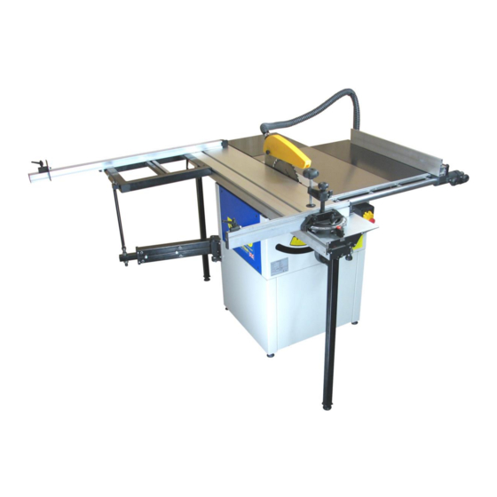
- Page 1 10” PANEL SAW OWNERS MANUAL MODEL: W660 Charnwood, Cedar Court, Walker Road, Hilltop Industrial Estate, Bardon, Leicestershire, LE67 1TU Tel. 01530 516 926 Fax. 01530 516 929 email: sales@charnwood.net website: www.charnwood.net...
-
Page 2: General Safety Rules
GENERAL SAFETY RULES WARNING: Do not attempt to operate the machine until you have read thoroughly and understood completely all instructions, rules, etc. contained in this manual. Failure to comply may result in accidents involving fire, electric shock, or serious personal injury. Keep this owner's manual and review frequently for continuous safe operation. - Page 3 14. Maintain the machine in good condition. Keep the machine clean for best and safest performance. Follow instructions for lubrication and changing accessories. 15. Disconnect the machine from power source before servicing and when changing the blade. 16. Never leave the machine running unattended. Turn the power off. Do not leave the machine until it comes to a complete stop.
-
Page 4: Specification
Note: This table saw has been designed and built solely as a woodworking machine. Do not modify it in any way or use for anything other than its designated purpose. Neither the manufactures nor the supplies are liable for any damage or injury caused by incorrect assembly, operation or electrical connection of this machine. - Page 5 Unpacking The saw is shipped in two parts. Open both packing cases and carefully unpack all of the contents. Familiarise yourself with the parts You will find these parts and the sliding table (not shown) packed at the sides of the machine. Open the blue access panel and retrieve the items shown in the picture above.
- Page 6 Assembly Tilt the machine to one side and prop it up securely. Screw in 2 feet, repeat for the other side and adjust them so that the saw is level and stable. The feet have spanner flats to assist. You will have to remove this fixing plate from one corner.
- Page 7 Use the long fence again to check the level of all 3 tables. Take the sliding beam support arm and remove the setscrew and nut from its end. Insert the support arm into the hinged arm, as shown. You may feel a slight resistance as it engages with the internal bearings.
- Page 8 Tighten the Tee bolt nuts. The outer threaded rods facilitate adjustment of the beam, so that it is level with the table. These are factory preset and should not need adjustment. Remove the four bolts from the sliding table. Using the ratchet locking levers, loosen this Tee- bar and pull it out from the table so that the gap between it and the table is at least 5mm.
- Page 9 Raise the blade, loosen the nut and bolt through the crown guard and fit it over the riving knife. Tighten the black nut so that the guard is secure. Fit the second hand wheel to the spindle protruding from the right hand side of the saw. This controls the blade angle.
- Page 10 Take the rip fence guide rail and remove one nut and washer from each stud. Ensure that the hole in one end of the guide is on the right. Place the studs through the holes in the front of the table and replace the nuts and washers.
- Page 11 Locate the stud into hole at the back right hand corner of the sliding table. The bolt should then be passed into the slot between the two table rails. Fit the washer and ratchet lever back on. The fence can now be pivoted to the desired angle, which is reads off the scale.
- Page 12 The machine is fitted with an NVR (No Voltage Release) switch. This type of switch is designed so that if the machine is disconnected from the mains whilst running and then reconnected, the motor will not automatically restart. Cutting Depth Adjustments to the cutting depth should be made only when the saw is not running.
-
Page 13: Changing The Blade
An alternative configuration is available for the sliding table. The fence can be assembled onto the front of the frame, so that the work piece is loaded against the back edge of the fence and then fed onto the blade. Using this configuration, the crosscut capacity is reduced, however some people to prefer to work this way. -
Page 14: Troubleshooting
When pressing start, nothing happens Check power supply, fuse in plug and switch. Declaration of Conformity for CE Marking Charnwood Declare that Woodworking Circular Saw, Model W660 Conforms with the following Directives: Machinery Directive 2006/42/EC Low Voltage Directive 2006/95/EC And further conforms to the machinery example for which the EC type examination Certificate No. - Page 15 CHARNWOOD W660 PARTS DIAGRAM A...
- Page 16 CHARNWOOD W660 PARTS LIST A A001 Hand Wheel A002 Screw M6 x 16mm A003 C Ring, 12 A004 Bearing GE12E A005 C Ring, 22 A006 Bracket A007 Thread Spindle A008 Large Washer 8mm A009 Spring Washer 8mm A010 Hex Bolt M8 x 65mm...
- Page 17 Screw M6 x 16mm A111 Washer M6 A112 Hex Nut M6 A113 Underprop A114 Support Column A115 Screw M8 x 12mm A116 Fixing Plate A117 Screw M6 x 12mm A118 Very Large Washer M6 A119 Square Nut CHARNWOOD W660 PARTS DIAGRAM B...
- Page 18 CHARNWOOD W660 PARTS LIST B Thread Nut Thread Spindle Bush Washer Bush C Ring 8 Hex Locking Nut M6 Large Washer M6 Limited Plate Space Bush Screw M6 x 3.5mm Screw M4 x 10mm Large Washer M4 Dust Collector Screw M6 x 20mm...
- Page 19 CHARNWOOD W660 PARTS DIAGRAM C CHARNWOOD W660 PARTS LIST C Square Nut Stopping Plate Hex Nut M6 Large Washer M6 Hex Bolt M6 x 20mm Handle Assembly Screw M4 x 10mm Fence Insert T shaped Bolt Stopping Bolt Locking Plate...
- Page 20 CHARNWOOD W660 PARTS DIAGRAM D CHARNWOOD W660 PARTS LIST D Micro Adjust Handle Wave Washer M6 Large Washer M6 Locking Handle Micro Adjust Support Clamp Thin Hex Nut M6 Thumb Nut Large Washer M6 Linking Plate Square Neck Bolt M6 x 35mm...
Need help?
Do you have a question about the W660 and is the answer not in the manual?
Questions and answers