Table of Contents
Advertisement
Quick Links
Information contained herein is classified as EAR99 under the
U.S. Export Administration Regulations.
Export, reexport or diversion contrary to U.S. law is prohibited.
OPERATING INSTRUCTIONS FOR
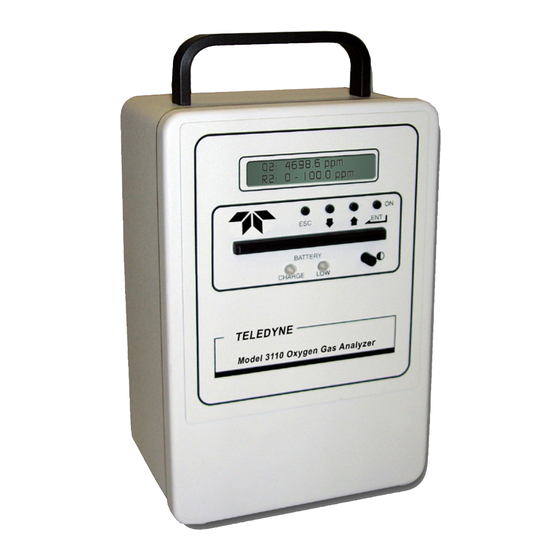
Model 3110P
Portable Percent
Oxygen Analyzer
Toxic gases and or flammable liquids may be present in this monitoring system.
Personal protective equipment may be required when servicing this instrument.
Hazardous voltages exist on certain components internally which may persist
for a time even after the power is turned off and disconnected.
Only authorized personnel should conduct maintenance and/or servicing.
Before conducting any maintenance or servicing, consult with authorized
supervisor/manager.
Teledyne Analytical Instruments
Use and Disclosure of Data
DANGER
P/N M3110P
4/1515
Advertisement
Table of Contents

Related Manuals for Teledyne Analytical Instruments 3110P


Summary of Contents for Teledyne Analytical Instruments 3110P
- Page 1 Use and Disclosure of Data Information contained herein is classified as EAR99 under the U.S. Export Administration Regulations. Export, reexport or diversion contrary to U.S. law is prohibited. OPERATING INSTRUCTIONS FOR Model 3110P Portable Percent Oxygen Analyzer P/N M3110P 4/1515 DANGER Toxic gases and or flammable liquids may be present in this monitoring system.
- Page 2 ...
- Page 3 Model 3110P Copyright © 2015 Teledyne Instruments/ Analytical Instruments All Rights Reserved. No part of this manual may be reproduced, transmitted, transcribed, stored in a retrieval system, or translated into any other language or computer language in whole or in part, in any form or by any means, whether it be electronic, mechanical, magnetic, optical, manual, or otherwise, without the prior written consent of Teledyne Instruments/Analytical Instruments, 16830 Chestnut Street, City of Industry, CA 91748.
-
Page 4: Specific Model Information
Nylon cell block 316 SS cell block Sample System: Standard sample system Stainless steel with glass flowmeter Stainless steel with regulator and glass flowmeter Data Logger Option Quick Disconnect Fittings Teledyne Analytical Instruments... -
Page 5: Safety Messages
Model 3110P Safety Messages Your safety and the safety of others is very important. We have provided many important safety messages in this manual. Please read these messages carefully. A safety message alerts you to potential hazards that could hurt you or others. - Page 6 Manuals do get lost. Additional manuals can be obtained from TAI at the address given in the Appendix. Some of our manuals are available in electronic form via the internet. Please visit our website at: www.teledyne-ai.com. Teledyne Analytical Instruments...
-
Page 7: Table Of Contents
Model 3110P Table of Contents Specific Model Information ............iii Safety Messages ................iv List of Figures ................viii Introduction ................... 1 1.1 Introduction 1.2 Features 1.3 Method of Analysis 1.4 Micro-Fuel Cell 1.4.1 Cell Warranty 1.5 Accuracy and Response 1.6 Signal Output... - Page 8 4.1 Routine Maintenance 4.2 Opening the Instrument Case 4.3 Replacing the Battery 4.4 Battery Power Supply Service 4.5 Cell Replacement 4.6 Cell Warranty 4.7 Temperature Compensation 4.8 Leak Testing Appendix ..................31 A.1 Specifications A.2 Spare Parts List Teledyne Analytical Instruments...
-
Page 9: List Of Figures
Model 3110P List of Figures Figure 1-1: Model 3110 Portable Trace Oxygen Analyzer ....2 Figure 2-1: Model 3110 Rear Panel ..........8 Figure 3-1: Front Panel Keys ............14 Figure 3-2: Available Menus and Their Sequence ......15 Figure 4-1: Battery Charger Port on the Model 3110 ....27 Figure 4-2: Effects of CO2 on B-2 Cell Life ........ - Page 10 Since the use of this instrument is beyond the control of Teledyne Analytical Instruments, referred as TAI, no responsibility by TAI, its affiliates, and agents for damage or injury from misuse or neglect of this equipment is implied or assumed.
-
Page 12: Introduction
Because of the intrinsically safe design, the instrument can be employed even in hazardous environments without compromise once calibrated. The Model 3110P incorporates a large standard feature list designed for versatile, accurate oxygen analysis for a wide range of applications. -
Page 13: Features
This instrument is designed to be versatile analytical instrument and to perform reliably and accurately in analyzing oxygen concentrations in gas mixtures from ppm levels through 25% oxygen. The following features are standard on the Model 3110P: Display: A 2-line 20 character alphanumeric LCD... -
Page 14: Method Of Analysis
9-pin serial interface. Real-time Clock: This feature allows the Model 3110P to date and time stamp the data set recorded on the data logger. It uses a 24 hour clock. Quick Disconnect Fittings: Dual self-sealing quick disconnect fittings are installed for easy sample connections. -
Page 15: Micro-Fuel Cell
MISHANDLING WILL RENDER THE CELL WARRANTY NULL AND VOID. The Model 3110P is rated as intrinsically safe and may be used in a Class I, Div 1, Group A-D hazardous environments. This safety feature does not apply when the instrument is being charged with the 100- 240 VAC external charge adapter. -
Page 16: Accuracy And Response
With a sample flowrate of 1 SCFH, a 90% response can be achieved in 10 seconds when analyzing in the percent range. The response time on the 3110P is limited by the filter setting. 1.6 Signal Output This analyzer includes a 0-1 VDC output as standard. This signal is suitable for driving external devices that have an input impedance of 10,000 ... - Page 17 Introduction Model 3110 BLANK PAGE Teledyne Analytical Instruments...
-
Page 18: Charging The Batteries
The instrument should not be left on the charger for longer than 20 hours nor should the charger be left attached to the instrument when the unit is not charging. The Model 3110P cannot be operated while the battery charger is attached. -
Page 19: Gas Connections
Signal Output Sample In and Vent Connections Figure 2-1: Model 3110P Rear Panel 2.2 Gas Connections The customer must provide a means of controlling the pressure and flowrate of the applied gas. For positive pressure applications, TAI suggests a simple throttle valve installed in the sample line between the sample point and the analyzer. - Page 20 For percent measurement applications, flowmeters or rotameters (with or without control valves) can be placed upstream of the analyzer, i.e. on the Sample In line. Teledyne Analytical Instruments...
-
Page 21: Sensor Installation
Installation Model 3110 2.3 Sensor Installation The Model 3110P can accept various percent oxygen sensors. For most applications the B1 or A5 sensor is used. The installation procedure is similar for either sensor. 2.3.1 Installing the Percent Sensor To install a percent sensor: 1. -
Page 22: Set The Sample Flowrate
Once the sample gas is flowing, set the flow rate to 0.2-2.5 SCFH. 2.6 External Signal A 0-1 VDC output signal is included with the Model 3110P. When installed, the output signal represents the percentage of oxygen in the current range. For instance, if the range was set for 0 to 10%, then 0.1 V would represent 1%, 0.2V would be 2%;... - Page 23 Installation Model 3110 Teledyne Analytical Instruments...
-
Page 24: Front Panel Interface
3.1 Front Panel Interface The Model 3110P is controlled from the keys on the front panel and is shown in Figure 3-1. These keys are also used to setup the instrument for your application. The keys are: ... -
Page 25: Escape Key
Increment or decrement a value 3.2 Operation and Setup Screens and Menus The Model 3110P operation and setup functions are arranged in a set of 15 menus. All but the POWER ON screen are accessible via the Teledyne Analytical Instruments... -
Page 26: Power On Screen
The POWER ON screen automatically appears on the display when the unit is first powered up. The display appears briefly and shows the model number and software version. After a few seconds the display reverts to the HOME screen. Teledyne Analytical Instruments... -
Page 27: Home Screen
2. Use the UP/DOWN keys to alter the month. Then press ENTER. The cursor will move over to the next editable field. 3. Use the UP/DOWN keys to alter the day. Then press ENTER. The cursor will move over to the next editable field. Teledyne Analytical Instruments... -
Page 28: Time Screen
At any time you can press the ESC key to abort the entry and return to the DATE screen. 3.2.5 AO Rng Screen In this screen, the user defines the analysis range which sets the scaling of the analog output to correspond to the range setting. For Teledyne Analytical Instruments... -
Page 29: Span Value Screen
The SPAN VALUE screen displays the oxygen concentration of the span gas used for calibration. This is not a measured value; it is the known span gas concentration that is input to the analyzer by the operator. Teledyne Analytical Instruments... -
Page 30: Span Screen
3.2.7 SPAN Screen This screen is used to perform a span calibration on the Model 3110P. The appropriate span value must have already been input to the instrument. See Section 3.2.6 for entering a span value into the analyzer. CAUTION:... -
Page 31: Filter Screen
3.2.8 Filter Screen The 3110P includes user an adjustable digital filter. The filter has settings from 1-10. Setting 1 is the least amount of filtering and 10 is the highest level of damping. The filter is used to reduce the noise level of the O readings. -
Page 32: Log Intv Screen (Optional)
1. Use the UP/DOWN keys to navigate to the LOG RESET & START screen and press ENTER. 2. When the screen begins to blink press ENTER again to start the data logger. Once the data logger has started, the screen Teledyne Analytical Instruments... -
Page 33: Log Transmit Screen
Refer to your computer manual for details on how to setup the RS- 232 communications port on your computer. To download a data log: 1. Use the UP/DOWN keys to navigate to the LOG TRANSMIT screen. Then press ENTER to enter the setup screen. Teledyne Analytical Instruments... -
Page 34: Power Down Screen
To turn the analyzer off: 1. Use the UP/DOWN keys to navigate to the POWER DOWN screen. Then press ENTER. 2. Press ENTER again to turn the instrument OFF. In a few seconds the analyzer will turn off. Teledyne Analytical Instruments... - Page 35 Operation Model 3110 Teledyne Analytical Instruments...
-
Page 36: Maintenance & Troubleshooting
Refer to the Spare Parts Listing in the Appendix for the correct replacement battery. Note: The batteries should only be replaced by a qualified technician. Teledyne Analytical Instruments... -
Page 37: Battery Power Supply Service
Model 3110 4.4 Battery Power Supply Service The Model 3110P is designed to be intrinsically safe, and is designed for use only when not connected to the AC power line. TAI suggests that an overnight recharge be performed every few days for continuous use. -
Page 38: Cell Replacement
Portable Trace Oxygen Analyzer Maintenance Battery Charger Figure 4-1: Battery Charger Port on the Model 3110P 4.5 Cell Replacement The characteristics of the micro-fuel cell are similar to those of a NiCad battery in that both provide an almost constant output through their useful life, and then fall off sharply towards zero at the end. -
Page 39: Cell Warranty
(or the sample), and then proceed as directed in section 3.1.1. 4.6 Cell Warranty The majority of micro-fuel cells used in the Model 3110P carry a six-month warranty from date of service. With regard to spare cells, service time starts when the cell is removed from its shipping package. -
Page 40: Temperature Compensation
4. Note how much the reading has changed after a few minutes. 5. Reduce the flowrate to 0.5 SCFH. 6. Note how much the reading has changed. 7. The reading should change by less than 10% of the original value Teledyne Analytical Instruments... -
Page 41: Figure 4-2: Effects Of Co2 On B-2 Cell Life
6. The CO effect on B-2 cells is independent of the O level. Usage in contributes significantly to cell life reduction and thus affects cell warranty. Figure 4-2: Effects of CO2 on B-2 Cell Life Teledyne Analytical Instruments... -
Page 42: Appendix
Uo = 4.65 V, Io = 193.74 mA, Po = 225.2 mW, Co = 90 uF, Lo = 0.7 mH, Lo/Ro = 157.86 uH/Ohm Dimensions: 10.9” x 6.2” x 5.2” deep Weight: 4.4 lbs. (2.0 kg.) Power Requirements: 100-240 VAC 47-63 Hz Charging Adapter Teledyne Analytical Instruments... -
Page 43: Spare Parts List
IMPORTANT: Orders for replacement parts should include the model number, serial number, and range of the analyzer for which the parts are intended. Orders should be sent to: TELEDYNE ANALYTICAL INSTRUMENTS 16830 Chestnut Street City of Industry, CA 91748 Phone: (626) 961-9221...
Need help?
Do you have a question about the 3110P and is the answer not in the manual?
Questions and answers