Table of Contents
Advertisement
Quick Links
Information contained herein is classified as EAR99 under the
U.S. Export Administration Regulations.
Export, reexport or diversion contrary to U.S. law is prohibited.
Paramagnetic Oxygen Analyzer
OPERATING INSTRUCTIONS FOR
MODEL 3020M
ATEX/IECEx
Paramagnetic Oxygen Analyzer
Toxic and or flammable gases may be present in this monitoring system.
Personal protective equipment may be required when servicing this instrument.
Hazardous voltages exist on certain components internally which may persist
for a time even after the power is turned off and disconnected.
Only authorized personnel should conduct maintenance and/or servicing.
Before conducting any maintenance or servicing, consult with authorized
supervisor/manager.
Teledyne Analytical Instruments
Use and Disclosure of Data
DANGER
P/N M94944
1/15/2019
i
Advertisement
Table of Contents

Related Manuals for Teledyne Analytical Instruments 3020M


Summary of Contents for Teledyne Analytical Instruments 3020M
- Page 1 Use and Disclosure of Data Information contained herein is classified as EAR99 under the U.S. Export Administration Regulations. Export, reexport or diversion contrary to U.S. law is prohibited. Paramagnetic Oxygen Analyzer OPERATING INSTRUCTIONS FOR MODEL 3020M ATEX/IECEx Paramagnetic Oxygen Analyzer P/N M94944 1/15/2019 DANGER Toxic and or flammable gases may be present in this monitoring system.
- Page 9 Teledyne Analytical Instruments, the manufacturer of this instrument, cannot accept responsibility for conditions beyond its knowledge and control. No statement expressed or implied by this document or any information disseminated by the manufacturer or its agents, is to be construed as a warranty of adequate safety control under the user’s process...
- Page 10 Instrument Serial Number: _______________________ Options Included in the Instrument with the Above Serial Number: 0-1% Special Sensor/Heater Auto Calibration Gas Panel with Flowmeter 1/4” Tube Connections Teledyne Analytical Instruments...
- Page 11 Model 3020M-ATEX Blank Page Teledyne Analytical Instruments...
-
Page 12: Safety Messages
Failure to heed this warning could result in injury and/or death from electrocution. Technician Symbol: All operations marked with this symbol are to be performed by qualified maintenance personnel only. Teledyne Analytical Instruments... - Page 13 Model 3020M-ATEX Note: Additional information and comments regarding a specific component or procedure are highlighted in the form of a note. Symbol CAUTION: THE ANALYZER SHOULD ONLY BE USED FOR THE PURPOSE AND IN THE MANNER DESCRIBED IN THIS MANUAL.
-
Page 14: Atex/Iecex Certified Product
ATEX/IECEx Certified Product This unit is ATEX and IECEx certified, no modifications are permitted without reference to Intertek. ATEX: ITS17ATEX102893X IECEX: IECEx ETL 17.0067X Teledyne Analytical Instruments... -
Page 15: Special Conditions For Safe Use
Model 3020M-ATEX Special Conditions for Safe Use Due to the window, the unit shall only be located in an area of low impact. Note: The pilot light EFL PC and the covers with windows have only been tested with a shock corresponding to a low risk energy of 2 joules. -
Page 16: Additional Atex/Iecex Information
This instrument uses flameproof joints that have different values from those specified in the tables of the IEC 60079-1 standard. If repairs are needed, please contact Teledyne Customer Service at the address below. Teledyne Analytical Instruments 16830 Chestnut Street City of Industry, CA 91748 Phone... - Page 17 Model 3020M-ATEX Blank Page Teledyne Analytical Instruments...
-
Page 18: Table Of Contents
1.5.2 ESCAPE/ENTER Switch 1.5.3 Displays 1.6 Recognizing Difference Between LCD & VFD 1.7 Equipment Interface 1.7.1 Electrical Connector Panel 1.7.2 Gas Connector Panel (Option) Operational Theory ..............11 2.1 Introduction 2.2 Precise Paramagnetic Sensor 2.2.1 Principles of Operation Teledyne Analytical Instruments... - Page 19 Model 3020M-ATEX 2.3 Cross interference 2.4 Sample System 2.5 Electronics and Signal Processing 2.6 Temperature Control Installation ................... 21 3.1 Unpacking the Analyzer 3.2 Mounting the Analyzer 3.3.1 Primary Input Power 3.3.2 Fuse Installation 3.3.3 Analog Outputs 3.3.4 Alarm Relays 3.3.5 Digital Remote Cal Inputs...
- Page 20 4.12 The STANDBY Function 4.13 The Analysis Mode Maintenance ................. 59 5.1 Routine Maintenance 5.2 Major Internal Components 5.3 Cell Replacement 5.4 Fuse Replacement 5.5 System Self Diagnostic Test Appendix ..................63 Specifications Recommended 2-Year Spare Parts List Drawing List Teledyne Analytical Instruments...
-
Page 21: List Of Figures
Figure 3-2: Flame Paths ..............23 Figure 3-3: Required Front Door Clearance ........23 Figure 3-4: Front and Side View of the Model 3020M-ATEX..24 Figure 3-5: Electrical Connector Panel ......... 25 Figure 3-6: Primary Input Power Connections ....... 26 Figure 3-7: Analog Output Connections ........ - Page 22 Paramagnetic Oxygen Analyzer Figure 5-1: Major Internal Components (0-1% Version with Auto- Cal and optional Gas Panel and Flowmeter shown) ... 60 Figure 5-2: Removing Fuse Cap and Fuse from Holder ....61 Teledyne Analytical Instruments...
-
Page 23: List Of Tables
Model 3020M-ATEX List of Tables Table 3-1: Analog Concentration Output—Example ..... 27 Table 3-2: Analog Range ID Output—Example......28 Table 3-3: RS-232 Signals ............32 Table 3-4: Commands via RS-232 Input ........32 Table 3-5: Required RS-232 Options ..........33... -
Page 24: Introduction
ATEX/IECEx certified explosion-proof, bulkhead-mount Model 3020M Percent Oxygen Analyzer: the standard 0-5% version and 0-1% version. 1.2 Typical Applications A few typical applications of the Model 3020M are: Monitoring inert gas blanketing Air separation and liquefaction Chemical reaction monitoring ... -
Page 25: Model Designations
Introduction Model 3020M-ATEX Versatile analysis over a wide range of applications. Microprocessor based electronics: 8-bit CMOS microprocessor with 32 kB RAM and 128 kB ROM. Three user definable output ranges: Standard ranges: 0-5% through 0-100% (std. -
Page 26: Operator Interface
The displays and controls are described briefly here and in greater detail in chapter 4. Figure 1-1 shows the standard 3020M with without the optional gas panel. Figure 1-2 is the same instrument with a gas panel. -
Page 27: Up/Down Switch
Introduction Model 3020M-ATEX Figure 1-2: Standard Model 3020M-ATEX With Gas Control Panel The standard tube connections are 6 mm but other sizes are available. 1.5.1 UP/DOWN Switch Functions: The UP/DOWN switch is a 3-way switch used to select the function to be performed. Choose UP or DOWN to scroll through the following list of eleven functions: ... -
Page 28: Escape/Enter Switch
Digital Meter Display: The meter display is a LED device that produces large, bright, 7-segment numbers that are legible in any lighting. It produces a continuous readout from 0-100%. It is accurate across all analysis ranges without the discontinuity inherent in analog range switching. Teledyne Analytical Instruments... -
Page 29: Recognizing Difference Between Lcd & Vfd
Introduction Model 3020M-ATEX Alphanumeric Interface Screen: The backlit VFD screen is an easy-to-use interface from operator to analyzer. It displays values, options, and messages that give the operator immediate feedback. Flowmeter: Monitors the flow of gas past the sensor. Readout is 100 to 1000 standard cubic centimeters per minute (SCCM). -
Page 30: Figure 1-3: Electrical Connector Panel
0-1 VDC concentration plus 0-1 VDC range ID and isolated 4-20 mA DC plus 4-20 mA DC range ID. • Alarm Connections 2 concentration alarms and 1 system alarm. • RS-232 Port Serial digital concentration signal output and control input. Teledyne Analytical Instruments... -
Page 31: Gas Connector Panel (Option)
6 mm gas connections for external inlets and outlets (other size fittings are available on request). The connections are described briefly here and in detail in the Installation chapter of this manual. Figure 1-4: Model 3020M Optional Gas Connector Panel Teledyne Analytical Instruments... - Page 32 3020M electronics. Note: If you require highly accurate Auto-Cal timing, use external Auto-Cal control where possible. The internal clock in the Model 3020M is accurate to 2-3%. Accordingly, internally scheduled calibrations can vary 2-3% per day. Teledyne Analytical Instruments...
- Page 33 Introduction Model 3020M-ATEX Blank Page Teledyne Analytical Instruments...
-
Page 34: Operational Theory
2.2 Precise Paramagnetic Sensor 2.2.1 Principles of Operation The heart of the 3020M is a paramagnetic type oxygen sensor that is maintenance free and has a long lifetime. Both the standard 3020M sensor (P/N S1731) and the 0-1% sensor (P/N S1638) are both paramagnetic sensors however the sensors are different and not interchangeable. -
Page 35: Figure 2-1: Sensor (Side View Shown)
Operational Theory Model 3020M-ATEX light source, a mirror at the dumbbell axis and a pair of detectors. The difference between the compensating currents required to bring the dumbbell to the zero position in the presence of zero gas (i.e. no O present) or of sample gas is proportional to the partial pressure of oxygen in the sample gas. -
Page 36: Figure 2-2: Sensor (Rear View Shown)
The electronics and heating elements require a separate power source, from the rest of the 3020M capable of delivering 1.5 amps approximately at 24 volts DC. The output of the sensor is roughly calibrated to be 0 to 1 volt DC for the range of 0 to 100% O . - Page 37 Operational Theory Model 3020M-ATEX 10 Not used 11 Negative reference voltage (not connected) 12 Positive reference voltage (not connected) 13 Nominal temperature voltage signal (not connected) 14 Actual temperature voltage signal (not connected) 15 +24 VDC power. Pin out (0-1% Version): Description Pin No.
-
Page 38: Cross Interference
Oxygen. It is actually displaying the cross sensitivity to another gas. The following table shows the cross sensitivity of some gases when changing from pure nitrogen to 100% of one of the gases listed. Teledyne Analytical Instruments... -
Page 39: Sample System
0% - (-0.137) = + 0.137% O 2.4 Sample System The Model 3020M sample system is designed and fabricated to ensure that the oxygen concentration of the gas is not altered as it travels through the sample system. The sample encounters almost no dead space. -
Page 40: Figure 2-3: Flow Diagram
The shaded portions of the diagram show the components added when the —C and/or —F options are ordered. The solenoid valves, when supplied, are installed inside the 3020M enclosure and are regulated by the instruments internal electronics. The flame arrestors, when supplied, are installed in the Gas Connector Panel.. -
Page 41: Electronics And Signal Processing
This current is converted to a voltage, which is preamplified in the sensor internal electronics. The preamplified signal (0-1 Volt) is fed to the 3020M amplifier for minor processing. The digital concentration signal along with input from the control panel is processed by the microprocessor, and appropriate control signals are directed to the display, alarms and communications port. -
Page 42: Figure 2-4: Block Diagram Of The Model 3020M Electronics
PROCESS. ALWAYS CHECK WITH TELEDYNE CUSTOMER SERVICE BEFORE MAKING ANY TEMPERATURE CONTROLLER ADJUSTMENTS. Refer to the included manual for the temperature controller for instructions on changing the temperature setpoint. Figure 2-4: Block Diagram of the Model 3020M Electronics Teledyne Analytical Instruments... - Page 43 Operational Theory Model 3020M-ATEX Blank Page Teledyne Analytical Instruments...
-
Page 44: Installation
Do not forget to allow an extra 1 3/8" for the hinges. The 3020M MUST be mounted in an upright position as shown in Figure 3-1. The paramagnetic sensor is orientation sensitive and will not work properly if operated horizontally (on its back or side). -
Page 45: Figure 3-1: Mounting The Analyzer
Installation Model 3020M-ATEX CAUTION: ALL ENTRIES MUST BE PROPERLY SEALED PRIOR TO PLACING THE ANALYZER INTO SERVICE. ALL DOOR RETAINING HARDWARE MUST BE PROPERLY INSTALLED PRIOR TO PLACING THE ANALYZER IN SERVICE. Figure 3-1: Mounting the Analyzer The enclosure must be grounded. Refer to the Outline Diagram in the Appendix for the ground lug location. -
Page 46: Figure 3-2: Flame Paths
Paramagnetic Oxygen Analyzer Installation Figure 3-2: Flame Paths Figure 3-3: Required Front Door Clearance Teledyne Analytical Instruments... -
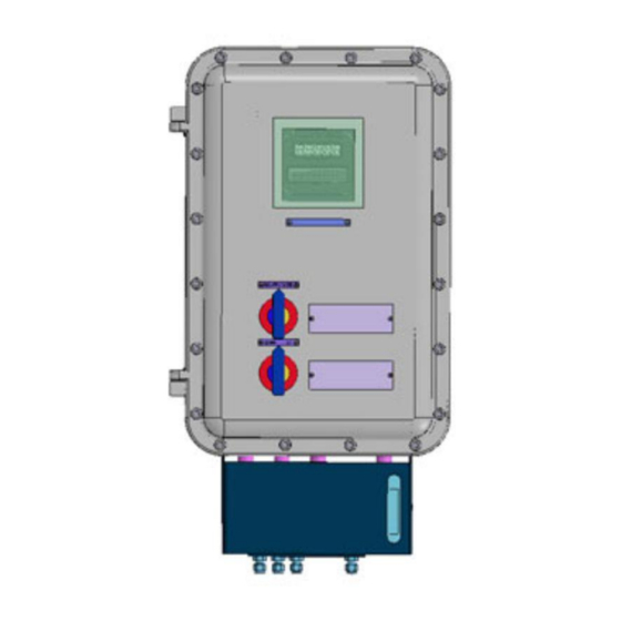
Page 47: Figure 3-4: Front And Side View Of The Model 3020M-Atex
Installation Model 3020M-ATEX Figure 3-4: Front and Side View of the Model 3020M-ATEX (shown with optional Gas Panel) CAUTION: ALL ENTRIES MUST BE PROPERLY SEALED PRIOR TO PLACING THE ANALYZER INTO SERVICE. Electrical Connections Figure 3-5 shows the Model 3020M Electrical Connector Panel. -
Page 48: Primary Input Power
The actual input voltage used must show in the window of the VOLTAGE SELECTOR switch before the power source is connected. See Figure 3-6 for detailed connections. DANGER: Power is applied to the instrument's circuitry as long as the instrument is connected to the power Teledyne Analytical Instruments... -
Page 49: Fuse Installation
Installation Model 3020M-ATEX source. The Standby function switches power on or off to the displays and outputs only. Figure 3-6: Primary Input Power Connections 3.3.2 Fuse Installation The fuse holders accept 5 x 20 mm, 4 A, type 250VAC fuses. Fuses are not installed at the factory. -
Page 50: Table 3-1: Analog Concentration Output-Example
For example, if the analyzer is set on a range that was defined as 0–10 % O , then the output would be as shown in Table 3-1. Table 3-1: Analog Concentration Output—Example Voltage Signal Current Signal Output (VDC) Output (mA DC) 10.4 12.0 13.6 15.2 16.8 18.4 20.0 Teledyne Analytical Instruments... -
Page 51: Alarm Relays
Installation Model 3020M-ATEX To provide an indication of the range, a second pair of analog output terminals are used. They generate a steady preset voltage (or current when using the current outputs) to represent a particular range. Table 3-2 gives the range ID output for each analysis range. -
Page 52: Digital Remote Cal Inputs
Remote Zero and Span Inputs: The REMOTE SPAN and REMOTE ZERO inputs are on the DIGITAL INPUT terminal block. They accept 0 V (OFF) or 24 VDC (ON) for remote control of calibration. (See Remote Calibration Protocol below.) Teledyne Analytical Instruments... - Page 53 (See Remote Calibration Protocol below.) Remote Calibration Protocol: To properly time the Digital Remote Cal Inputs to the Model 3020M Analyzer, the customer's controller must monitor the CAL CONTACT relay. When the contact is OPEN, the analyzer is analyzing, the Remote Cal Inputs are being polled, and a zero or span command can be sent.
-
Page 54: Range Id Relays
If you have the –C Internal valve option—which includes additional zero and span gas inputs—the 3020M automatically regulates the zero, span and sample gas flow. 3.3.6 Range ID Relays There are four dedicated RANGE ID CONTACT relays. -
Page 55: Table 3-3: Rs-232 Signals
Installation Model 3020M-ATEX Table 3-3: RS-232 Signals RS-232 Sig RS-232 Pin Purpose Data Carrier Detect Received Data Transmitted Data Data Terminal Ready Common Data Set Ready Request to Send Clear to Send Ring Indicator The data sent is status information, in digital form, updated every two seconds. -
Page 56: Remote Sensor And Solenoid Valves
Paramagnetic Oxygen Analyzer Installation The RS-232 protocol allows some flexibility in its implementation. Table 3-5 lists certain RS-232 values that are required by the 3020M implementation. Table 3-5: Required RS-232 Options Parameter Setting Baud 2400 Byte 8 bits Parity none... -
Page 57: Gas Connections
Installation Model 3020M-ATEX obtainable voltage, depending on the load impedance applied. See Figure 3-10. Figure 3-10: FET Series Resistance 3.4 Gas Connections Restrictors are located in the flame arrestors on all input lines and in the auto-cal assembly if equipped. - Page 58 These are additional ports for inputting span gas and zero gas. There are electrically operated valves inside for automatic switching between sample and calibration gases. These valves are completely under control of the 3020M Electronics. They can be externally controlled only indirectly through the Remote Cal Inputs, described below.
- Page 59 Installation Model 3020M-ATEX 3.5 Temperature Controller Settings (0-1% Analyzer only) The 0-1% Sensor uses a PID Temperature Controller to control an oven that surrounds the sensor. It has been set up at the factory for your application. Nevertheless, it is possible to make changes to the thermal environment if required however this should never be done without contacting Teledyne Customer Service first.
- Page 60 Check that the voltage selector switch on the Electrical Connector Panel is in the appropriate position for your power source. Power up the system, and test it by performing the following operations: 1. Repeat the Self-Diagnostic Test as described in Chapter 4, Section 4.3.5. Teledyne Analytical Instruments...
- Page 61 Installation Model 3020M-ATEX Blank Page Teledyne Analytical Instruments...
-
Page 62: Operation
Set alarm setpoints, and modes of alarm operation (latching, failsafe, etc). Establish a security password, if desired, requiring Operator to log in. Before you configure your 3020M these default values are in effect: Ranges: LO = 0-5%, MED = 0-25%, HI = 0-100%. Auto Ranging: ON Alarm Relays: Defeated, 10%, HI, Not failsafe, Not latching. -
Page 63: Mode/Function Selection
4.2.1.2 S ETUP The MAIN MENU consists of 12 functions you can use to customize and check the operation of the analyzer. Figure 4-1 shows the functions available with the 3020M. They are listed here with brief descriptions: Teledyne Analytical Instruments... - Page 64 All of these functions are described in greater detail in the procedures starting in section 4.3. The VFD screen texts used to Arial Narrow Bold illustrate the procedures are reproduced in the type style. Teledyne Analytical Instruments...
-
Page 65: Data Entry
Operation Model 3020M-ATEX Figure 4-1: Modes and Functions 4.2.2 Data Entry 4.2.2.1 ENTER When the selected option is a function on the Main Menu screen, the function name appears between the arrows on the screen. You activate the function by turning the ESCAPE/ENTER control to ENTER. -
Page 66: Escape
Note: If you require highly accurate timing of your AUTO-CAL, use external AUTO-CAL control where possible. The internal clock in the Model 3020M is accurate to 2-3 %. Accordingly, internally scheduled calibrations can vary 2- 3 % per day. -
Page 67: The Pwd (Password) Function
Operation Model 3020M-ATEX DOWN/UP to set the OFF/ON field to ON. You can now turn these fields ON because there is a nonzero span interval defined. 4.4 The PWD (Password) Function Security can be established by choosing a 5 digit password from the standard ASCII character set. -
Page 68: Installing Or Changing The Password
ENTER to change the password (to change either the default TETAI or the previously assigned password), or ESCAPE to keep the existing password and move on. If you choose ENTER to change the password, the password assignment screen appears. T E T A I <ENT> To Proceed Teledyne Analytical Instruments... - Page 69 Operation Model 3020M-ATEX A A A A A <ENT> To Proceed Enter the password using ENTER to scroll through the existing password letters, and DOWN/UP to change the letters to the new password. The full set of 94 characters available for password use are shown in the table below.
-
Page 70: The Logout Function
4.7 The SELF-TEST Function The Model 3020M has a built-in self-testing diagnostic routine. Preprogrammed signals are sent through the power supply, output board and sensor circuit. The return signal is analyzed, and at the end of the test the status of each function is displayed on the screen, either as OK or as a number between 1 and 3. -
Page 71: The Zero And Span Functions
Operation Model 3020M-ATEX During preamp testing there is a countdown in the lower right corner of the screen. When the testing is complete, the results are displayed. Power: OK Analog: OK Preamp: 3 The module is functioning properly if it is followed by OK. A number indicates a problem in a specific area of the instrument. -
Page 72: Zero Cal
Slope you will see a countdown: 5 Left, 4 Left, and so forth. These are five steps in the zeroing process that the system must complete, AFTER settling, before it can go back to Analyze. Teledyne Analytical Instruments... -
Page 73: Manual Mode Zeroing
Operation Model 3020M-ATEX #### Zero 1 Left=### ppm/s The zeroing process will automatically conclude when the output is within the acceptable range for a good zero. Then the analyzer automatically returns to the Analyze mode. 4.8.1.2 M ANUAL EROING Press Zero to enter the Zero function. The screen that appears allows you to select between automatic or manual zero calibration. -
Page 74: Span Cal
Use the DOWN/UPswitch to toggle between AUTO and MAN span settling. Stop when AUTO appears on the display. Span: Settling: AUTO <ENT> For Next Use ENTER to move to the next screen. Span Val: 20.90 <ENT>Span <UP>Mod # Teledyne Analytical Instruments... -
Page 75: Manual Mode Spanning
Operation Model 3020M-ATEX Use DOWN/UP to start changing the oxygen-concentration. Use ESCAPE/ENTER to blink the digit you are going to modify. Use DOWN/UP again to change the value of the selected digit. When you have finished typing in the concentration of the span gas you are using, repeatedly select ENTER until the rightmost digit is reached, then, the next ENTER will exit the Span Val screen. -
Page 76: The Alarms Function
ANALYZE function. 4.9 The ALARMS Function The Model 3020M is equipped with 2 fully adjustable concentration alarms and a system failure alarm. Each alarm has a relay with a set of form “C" contacts rated for 3 amperes resistive load at 250 V ac. - Page 77 Operation Model 3020M-ATEX One high and one low alarm, or Both low (low and low-low) alarms. 2. Are either or both of the alarms to be configured as failsafe? In failsafe mode, the alarm relay de-energizes in an alarm condition.
-
Page 78: The Range Function
0-1% 0-1% version) Med = 0–25% High = 0–100% The Model 3020M is set at the factory to default to auto-ranging. In this mode, the microprocessor automatically responds to concentration changes by switching ranges for optimum readout sensitivity. If the current range limits are exceeded, the instrument will automatically shift to the next higher range. -
Page 79: Setting The Analog Output Ranges
Operation Model 3020M-ATEX corresponding shift in the DC percent-of-range output, and in the range ID outputs, will be noticed. The auto-ranging feature can be overridden so that analog output stays on a fixed range regardless of the oxygen concentration detected. If the concentration exceeds the upper limit of the range, the DC output will saturate at 1 VDC (20 mA at the optional current output). -
Page 80: The Contrast Function
WARNING: THE POWER CABLE MUST BE UNPLUGGED TO FULLY DISCONNECT POWER FROM THE INSTRUMENT. WHEN THE ACCESS DOOR IS OPEN AND THE POWER CABLE IS CONNECTED, EXTRA CARE IS REQUIRED TO AVOID CONTACT WITH LIVE ELECTRICAL CIRCUITS. Teledyne Analytical Instruments... -
Page 81: The Analysis Mode
Operation Model 3020M-ATEX CAUTION: If you disconnect the primary power source from the analyzer, then on re-energizing, you will be required to choose to keep the configuration you previously programmed into your instrument in the Setup Mode by pressing the “Enter” key, or by pressing the “Escape”... -
Page 82: Maintenance
Figure 5-1 which shows the 0-1% version with the Auto Cal option and gas control panel. The fuse receptacle is shown in Figure 5-2. The 3020M contains the following major internal components: Paramagnetic Sensor Paramagnetic Sensor 24VDC Power Supply ... -
Page 83: Cell Replacement
Maintenance Model 3020M-ATEX See the drawings in the Drawings section in back of this manual for details. Figure 5-1: Major Internal Components (0-1% Version with Auto-Cal and optional Gas Panel and Flowmeter shown) To swing open the cover panel, remove all screws. -
Page 84: Fuse Replacement
WARNING: Risk of electric shock high voltage exposed at the end of enclosure! The 3020M requires two 5 x 20 mm, 4 A, T type (Slow Blow) fuses. The fuses are located inside the explosion proof housing on the Electrical Connector Panel, as shown in Figure 5-2. To replace a fuse: 1. -
Page 85: System Self Diagnostic Test
Maintenance Model 3020M-ATEX 5.5 System Self Diagnostic Test Use the DOWN/UP switch to scroll through the MAIN MENU to SELF-TEST. The screen will follow the running of the diagnostic. RUNNING DIAGNOSTIC Testing Preamp — 83 During preamp testing there is a countdown in the lower right corner of the screen. -
Page 86: Appendix
Diagnostics: Start-up or on-demand self-testing function. Response Time: 90% in 10 seconds or less. Displays: 2 line by 20 alphanumeric, VFD screen, and one 5 digit LED display. Digital Interface: Full duplex RS-232 communications port. Teledyne Analytical Instruments... - Page 87 Appendix Model 3020M-ATEX Power: User selectable power supply 115 or 230 VAC, at 50 or 60 Hz. Operating Temperature: 0-45°C Accuracy: ±1% of full scale at constant temperature. ±5% of full scale over operating temperature range, on factory default analysis ranges, once thermal equilibrium has been achieved.
-
Page 88: Recommended 2-Year Spare Parts List
Note: Orders for replacement parts should include the part number (if available) and the model and serial number of the instrument for which the parts are intended. Orders should be sent to: Teledyne Analytical Instruments 16830 Chestnut Street City of Industry, CA 91748 Phone... -
Page 89: Drawing List
Appendix Model 3020M-ATEX Drawing List C94974 Outline Drawing D94906, D94907 Wiring Diagrams B95024 Piping Diagram D94409, C94905 Interconnection Diagrams Teledyne Analytical Instruments...
Need help?
Do you have a question about the 3020M and is the answer not in the manual?
Questions and answers