Table of Contents
Advertisement
A5 GSM Control & Monitoring System
A5 GSM Control & Monitoring System
A5 GSM Control & Monitoring System
A5 GSM Control & Monitoring System
Installation and Setup Manual
Installation and Setup Manual
Installation and Setup Manual
Installation and Setup Manual
Firmware F6.05
Firmware F6.05
Firmware F6.05
Firmware F6.05
GSM850MHz, GSM900MHz
GSM850MHz, GSM900MHz
GSM850MHz, GSM900MHz
GSM850MHz, GSM900MHz
DCS1800MHz & PCS1900MHz
DCS1800MHz & PCS1900MHz
DCS1800MHz & PCS1900MHz
DCS1800MHz & PCS1900MHz
Access Control
Access Control
Access Control
Access Control
www.adventcontrols.co.uk
www.adventcontrols.co.uk
www.adventcontrols.co.uk
www.adventcontrols.co.uk
SMS Texter
SMS Texter
SMS Texter
SMS Texter
Emailer
Emailer
Emailer
Emailer
Auto- - - - Dialler
Auto
Auto
Auto
Dialler
Dialler
Dialler
Advertisement
Table of Contents

Related Manuals for Advent Controls A5

Summary of Contents for Advent Controls A5
- Page 1 A5 GSM Control & Monitoring System A5 GSM Control & Monitoring System A5 GSM Control & Monitoring System A5 GSM Control & Monitoring System Installation and Setup Manual Installation and Setup Manual Installation and Setup Manual Installation and Setup Manual Firmware F6.05...
-
Page 2: Table Of Contents
EMC/EMI Compliance Statement: CE Mark Declaration of Conformance Manufacturer's Disclaimer Statement: The information in this document is subject to change without notice and does not represent a commitment on the part of the vendor. No warranty or representation, either expressed or implied, is made with respect to the quality, accuracy or fitness for any particular purpose of this document. -
Page 3: Introduction
Setup can also be performed over the internet via GPRS using PC software. A5.02 v6 firmware devices are able to send emails to a single email addresses in addition to making calls and sending SMS messages. Additionally service information is available via email. -
Page 4: Number Types
Number Types When adding a telephone number to the system it can be set up as one of five different telephone number types with each type having a specific purpose. There is space for 512 numbers (1024 on selected C4 PCBs) and each number can be set up as any type of num- ber. -
Page 5: Command Message Format
The second LED, LED2 found by the 5 pin header, is used to display the result of a command. The LED will flash twice to acknowledge the successful receipt of a command and will light continuously for 2s to show the instruction has failed. It also illuminates during any call (valid or invalid) and lights continuously when a signal cannot be found (network dependent). -
Page 6: 2.4 Allowing Master Control For All Users
The result LED, LED2, will flash two times to indicate the master number has been success- fully setup. Calling the board’s telephone number with the master phone will now acti- vate the relay. Once one master number has been setup further masters (up to 512) can be setup by this and subsequent master phones without the jumper fitted (using the same message). -
Page 7: Viewing The Valid Number List
For example to remove a Call Number the ‘C’ character is appended after the word re- move as follows: REMOVEC 07574163361. This will only remove instances of the number 07574163367 that are stored as Call Numbers. The following shows the characters associated with each number type: T—Text Number C—Call Number M—Master Number... -
Page 8: Finding A Number In The Memory
Finding a Number in the Memory When a large number of numbers are stored in the memory using the LIST command can be impractical. To find whether an individual number is stored in the memory the master user sends the following command to the board: QUERY<space>number. -
Page 9: Call Reject
To disable activation of the relay by calling the following command is sent to the board (the relay can still be activated by SMS text; see OPEN/ON & CLOSE/OFF commands): CALL NONE To switch the inputs on and off the CALL DIALER command is used. There is no relay activa- tion by calling in this mode (although it can be activated by SMS text) CALL DIALER switches the inputs on and off (see section 4) -
Page 10: Relay Activation Mode
Relay Activation Mode When a valid call is received the relay can be set to activate for a set period of time (set by the RLYTIME command), to activate whilst the caller is ringing or to toggle between states on each call. By default the relay mode is set for timed (pulsed) activation. To switch to toggle mode the following message is sent to the system by the master number: RLYMODE TOG GLE enables toggle mode... -
Page 11: Exit Switch Enable
If the system loses power the relay state is restored when the power is reconnected! Exit Switch Enable The INPUTA connection can be used to activate the output relay which is ideal for con- nection to a secure-side exit switch. It uses the trigger level for the input text message (see INLVL) and activates the relay as per a phone call. -
Page 12: Input Change State Level
The maximum call length in auto-dialler mode is fixed at 5s. The maximum ring time (the time between dialling and call pick up) can be set using the RTIME command. The triggering of dialling and SMS messaging can be delayed using the HOLD command. If the input ceases to be active during the holding period the dialling and texting is can- celled. -
Page 13: Customising The Input Alert Message
Customising the Input Alert Message The default input alert message is ‘>INPUTX ACTIVE’. This can be customised by the user using the CUSTOM command for each input. The maximum length of the message is 127 characters and it must end with a full stop. The custom command is used as follows: CUSTOMA THE GATE IS OPEN. -
Page 14: Adding Sms Sender Text Numbers
STIME 25. sets the maximum line silence time to 25 seconds Adding Auto-dialler SMS Text Numbers The system can send the input triggered message (2.16) to up to all 511 numbers. To add a text num- ber the following SMS text message is sent to the system by any master number: TEXT<space>number. -
Page 15: Silencing The Alarm
4.14 Silencing the Alarm The bell –ve wire can be routed through the relay COM and NC terminals onto the bell. This al- lows the relay to break the connection when active and silence the alarm. Whilst the bell is sounding the SILENCE command can be used to silence the bell. -
Page 16: Power Up/Reset Text Message
To achieve an improved RSSI the standard antenna can be upgraded to a model with higher gain and/or the antenna should be positioned in an area with less physical ob- struction. An extension lead can be attached to the SMA connector on the PCB to lo- cate the antenna away from the control unit housing. -
Page 17: Web Security
You device has software embedded within it to establish a client connection with a PC or Advent Controls Web Interface Servers. The device never acts like a server and as such computers cannot connect to it; it must connect to an external server. -
Page 18: Connection To A Burglar Alarm
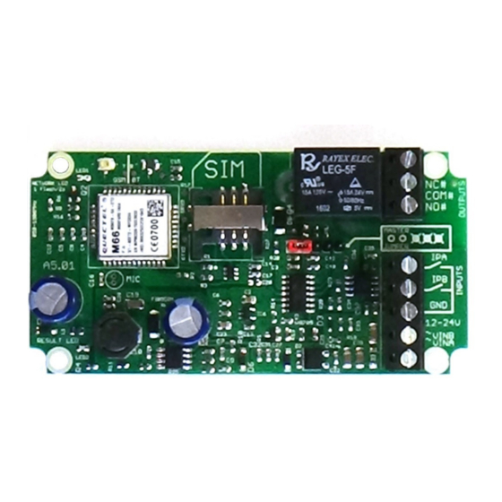
Input Circuit Reference Schematic Connection to a Burglar Alarm The system features an optically isolated input terminal which is driven low (to GND or -VE) in the active state. The A or B terminal is held at approximately 13V (or +VE if VIN is less than 13V) through a 4400 Ohm load. -
Page 19: Antenna Connection
Antenna Connection The standard antenna can be used where a good signal exists. In areas with a poor sig- nal an external antenna is recommended connected via RG174 coaxial cable. The sys- tem antenna connection is a male Hirose U.FL connector. The supplied pigtail is a U.FL female to SMA female connector. -
Page 20: Command Set Summary
Frequently Used Commands BOLD indicates default settings Command Action Comments ACKNOWLEDGE DISABLE ENABLE SMS on Relay Change State number Add User Number Set Access Point Name ANSWER CALL Answer Incoming Calls AUTODIAL THEN A>B Calling Logic ACCESS LIST NONE Call Handling CALL(A/B) number Add Autodial Call Number...
Need help?
Do you have a question about the A5 and is the answer not in the manual?
Questions and answers