Table of Contents
Advertisement
X5 GSM Control & Monitoring Systems
X5 GSM Control & Monitoring Systems
X5 GSM Control & Monitoring Systems
X5 GSM Control & Monitoring Systems
Installation and Setup Manual
Installation and Setup Manual
Installation and Setup Manual
Installation and Setup Manual
GSM850MHz, GSM900MHz
GSM850MHz, GSM900MHz
GSM850MHz, GSM900MHz
GSM850MHz, GSM900MHz
DCS1800MHz & PCS1900MHz
DCS1800MHz & PCS1900MHz
DCS1800MHz & PCS1900MHz
DCS1800MHz & PCS1900MHz
Open- - - - on
Open
Open
Open
Alarm Dialer & SMS Sender
Alarm Dialer & SMS Sender
Alarm Dialer & SMS Sender
Alarm Dialer & SMS Sender
Remote Voltage Monitoring
Remote Voltage Monitoring
Remote Voltage Monitoring
Remote Voltage Monitoring
Remote Relay Control
Remote Relay Control
Remote Relay Control
Remote Relay Control
Firmware F5.03
Firmware F5.03
Firmware F5.03
Firmware F5.03
on- - - - Call Access Control
Call Access Control
on
on
Call Access Control
Call Access Control
www.adventcontrols.co.uk
www.adventcontrols.co.uk
www.adventcontrols.co.uk
www.adventcontrols.co.uk
Advertisement
Table of Contents

Related Manuals for Advent Controls X5 Series

Summary of Contents for Advent Controls X5 Series
- Page 1 X5 GSM Control & Monitoring Systems X5 GSM Control & Monitoring Systems X5 GSM Control & Monitoring Systems X5 GSM Control & Monitoring Systems Installation and Setup Manual Installation and Setup Manual Installation and Setup Manual Installation and Setup Manual Firmware F5.03 Firmware F5.03 Firmware F5.03...
-
Page 2: Table Of Contents
Contents Introduction Product Selection an d Specification Number Types Numbers and Startup Registration Command Message Format Master Number Setup Allowing Master Control for All Users Adding a User Number Removing a User Number Viewing the Valid Number List Finding a Number in the Memory Clearing All Numbers and Settings 2.10 Result Acknowledgement Message... -
Page 3: Introduction
Introduction The Advent Controls X5 Series of GSM Alarm Dialler and SMS Sender Relay Boards allow for remote monitoring and control of electronic equipment. Primarily designed for security appli- cations these systems are ideal for use in burglar and fire alarm panels. -
Page 4: Number Types
Number Types When adding a telephone number to the system it can be set up as one of five different telephone number types with each type having a specific purpose. There is space for 512 numbers and each number can be set up as any type of number. For example you may wish to have 200 masters and 312 users. -
Page 5: Numbers And Startup
A call from a data number may leave the unit unresponsive for up to 3 minutes after the call has ended. Data numbers cannot activate the output relay. Details of the software are not covered in this manual. Please see the Advent Controls web- site/blog. -
Page 6: Master Number Setup
Master Number Setup The system is set up by any of the master cell phone numbers (see 1.2 Number Types). The system must first be associated with at least one master phone’s number before it can be used. To do this, the supplied 2.54mm jumper connector must be fitted to the pins on HDR1 as shown on the silk screen on the PCB. -
Page 7: 2.4 Allowing Master Control For All Users
Using the PIN for Master Setup The Master Number can also be set up using the PIN. This is only possible for the first master number that is added to the system. Subsequent masters must be added by a master using the MASTER command. -
Page 8: Viewing The Valid Number List
For example to remove a Call Number the ‘C’ character is appended after the word remove as follows: REMOVEC 07574163361. This will only remove instances of the number 07574163367 that are stored as Call Num- bers. The following shows the characters associated with each number type: T—Text Number C—Call Number M—Master Number... -
Page 9: Finding A Number In The Memory
Finding a Number in the Memory When a large number of numbers are stored in the memory using the LIST command can be impractical. To find whether an individual number is stored in the memory the master user sends the following command to the board: QUERY<space>number. -
Page 10: General Setup
General Setup Input/Output Status Message To determine the current status of the input and output terminals the STATUS com- mand is sent to the system telephone number by a master phone as follows: STATUS The system will respond with a SMS text message as follows: V5.XX OPEN#RELAY OFF relay 1 in-active... -
Page 11: Signal Strength Indicator
Inactivity Period (With No Chargeable Events) Mobile Network For Account Termination For Expiry of Unused Credit 180 days 180 days 6 months 6 months giffgaff 6 months 6 months 6 months 6 months Orange 180 days 270 days Talkmobile 6 months 6 months Tesco Mobile 6 months... -
Page 12: Power Up/Reset Text Message
Power Up/Reset Text Message The system can send an message to all the text numbers when a system reset or power up has occurred. This can be due to network failure or power cycling (power off followed by power on). Note the system repeatedly resets during network out- age. -
Page 13: Inverting The Relay Output
Inverting the Relay Output If desired the relay output can be inverted so that the Normally Open output termi- nal becomes the Normally Closed terminal and vice-verse. To invert the output the follow command is sent to the system: Normally Closed sets the Normally Open output to Normally Closed Normally Open sets the Normally Open output to Normally Open... -
Page 14: Relay Operation/Access Control
Relay Operation/Access Control Enabling Any Number and Disabling Open-on-Call The system can be setup to allow any number to operate the relay output. To enable any call the CALL command is used with the action ANY and is sent by the master phone in the following format: Call any To return the system to operate from only valid user numbers the LIST action is sent with... -
Page 15: Relay Activation Mode
To change the connect mode the CONN command is sent by the master phone with the action CL or OP. To disable connect on call the NOne action is sent. e.g. connect when input high CONN CL connect when input low CONN OP do not connect call CONN NO... -
Page 16: Exit Switch Enable
When sent with additional time information the relay is activated for however many sec- onds or minutes specified. e.g. activates relay indefinitely OPEN activates relay indefinitely 10 second activation time (s parameter optional) open 10. 250 second activation time Open 250s 1 minute activation time ON 1m. -
Page 17: Auto-Dialler/Sms Sender
Auto-dialler: Input Triggered SMS Text Message Sending and Autodialing The inputs can be used to trigger the sending of customisable SMS text messages to all of the ‘text numbers’ (see section 1.2 Number Types) and to sequentially dial all of the ‘call numbers’... -
Page 18: Input Change State Level
also valid; enables autodialing on input B inputa a input A is the default input if not specified input t inpc b INPD D Input Change State Level The INLEVEL commands sets the active state of the input for triggering the auto-dialler. For example, if the user requires triggering when the input is (going) closed (GND), then the following message is sent by the master number: trigger when input A closed (GND/-VE) -
Page 19: Customising The Input Alert Message
Customising the Input Alert Message The default input alert message is ‘>INPUTX ACTIVE’. This can be customised by the user using the CUSTOM command for each input. The maximum length of the message is 127 characters and it must end with a full stop. The custom command is used as follows: customised A message CUSTOMA THE GATE IS OPEN. -
Page 20: Changing The Maximum Call Time
Changing the Maximum Call Time The maximum time limit for an answered call is set using the CTIME command. The de- fault time limit is 45s. The CTIME command is specified in seconds and can be set from 1s to 255s. CTIME 45. -
Page 21: International Calling/Texting
5.11 International Calling/Texting The system can call/text international numbers, however the exit code should not be specified and should be replaced with the ‘+’ symbol e.g: UK Number 07574163367 should be entered as +447574163367 when outside the UK 5.12 Dial Now If necessary the system can make a call to a number not stored in it’s memory at any time. -
Page 22: Analogue Voltage Measurements
Analogue Voltage Measurements Analogue inputs 1 & 2 are able to measure voltages between 0V and 36V (accuracy 0.5v or better) When a voltage on the input exceeds the upper voltage limit the high SMS messages are sent to the text numbers and dialling commences. Similarly when a voltage drops below the lower voltage limit dialling commences and the low voltage message is sent to the text numbers associated with that input. -
Page 23: Gprs Software Pc Connection
GPRS PC Connection The system can connect to a PC running Advent Controls Remote Setup software. The most common method for accessing the system remotely using a PC is shown below Specifying the Access Point Name (APN) It is essential that your GSM network’s Access Point Name (APN) is specified. This informa- tion can typically be found from your network’s website. -
Page 24: Installation
(0v) supply to the GND terminal and the supply +ve to the outer-most ~VIN termi- nal (terminal number 5). This will bypass the bridge rectifier for the GND negative supply. Please note if using this equipment in a motor vehicle please consult Advent Controls prior to fitting (support@adventcontrols.co.uk) Current Consumption 1.8GHz (RSSI 9) D 4 .0 1 C ur r ent C o nsump t io n... -
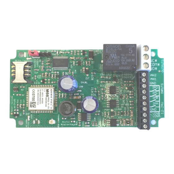
Page 25: Input Connection
Input Connection The inputs are optically isolated from the digital circuitry. Both inputs are active low and should be connected to the GND terminal in the active state. Input impedance is 4.4kΩ and is limited to 13V max. The input features protection against over-voltage but should not exceed 50V. -
Page 26: Output Connection
Output Connection The relay output has Normally Open (NO) and Normally Closed (NC) relative to COMmon (COM) connections. These can be actuated in a momentary operation or can be toggled (see 3 Setup). The connections are ‘voltage free’ with no connection to +VE or GND. The relay connections have a minimum creepage distance to GND greater than 5mm and are CATII rated to 220V. -
Page 27: Antenna Connection
Antenna Connection The standard antenna can be used where a good signal exists. In areas with a poor sig- nal an external antenna is recommended connected via RG174 coaxial cable. The sys- tem antenna connection is a male Hirose U.FL connector. The supplied pigtail is a U.FL female to SMA female connector. -
Page 28: Command Set Summary
SMS Command Set Summary Command Action Comments ENABLE SMS on Relay Change State ACKNOWLEDGE DISABLE Add User Number number ,“user” ,”password” Set Network APN “apn_name” THEN AUTODIAL NONE Call Handling CALL LIST Add Autodial Call Number CALLNUM(A/B) number Factory Reset (CLEAR ALL) CLEAR Deactivate Relay CLOSE...
Need help?
Do you have a question about the X5 Series and is the answer not in the manual?
Questions and answers