Advertisement
INSTALLER: THESE INSTRUCTIONS CONTAIN IMPORTANT SAFETY INFORMATION AND MUST BE FORWARDED TO THE BOAT OWNER.
INSTALLATION AND OPERATION OF MV-2
SERIES SIDE MOUNT CONTROL
OWNER'S MANUAL
NOTICE
nied by the International Hazard Symbol
instructions concerning a particular service or operation that may be hazardous if preformed incor-
rectly or carelessly.
Warnings alone do not eliminate dangers, nor are the a substitute for safe boat handling and proper
accident prevention measures. Observe these alerts carefully!
These "saftey alerts" alone cannot elim-
inate the hazards they signal. Strict
compliance to these special instruc-
tions when installing, operating or
performing maintanence and using
common sence are the most effective
accident prevention measures.
INSTALLATION MANUAL
Manual # 055001-518
Throughout this manual, Warnings and Cautions, accompa-
, are used to alert the manufacturer or installer to special
!
DANGER
!
Immediate Hazards which
WILL result in severe
personel injury or death.
CAUTION
!
Hazards or unsafe practices
which COULD result in injury,
product and/or property
damage.
Page 1
Revision 1
For Single Station Only
WARNING
!
Hazards or unsafe practices
which COULD result in sever
personel injury or death.
NOTICE
Information that is important to
the proper installation,
operation and maintenance, but
is not hazard related.
of 9
Advertisement
Table of Contents

Related Manuals for Teleflex MV-2 Series

Summary of Contents for Teleflex MV-2 Series
- Page 1 INSTALLATION MANUAL Page 1 of 9 Manual # 055001-518 Revision 1 INSTALLER: THESE INSTRUCTIONS CONTAIN IMPORTANT SAFETY INFORMATION AND MUST BE FORWARDED TO THE BOAT OWNER. INSTALLATION AND OPERATION OF MV-2 SERIES SIDE MOUNT CONTROL OWNER’S MANUAL For Single Station Only NOTICE Throughout this manual, Warnings and Cautions, accompa- nied by the International Hazard Symbol...
- Page 2 All specifi cations and features are subject to change with- out notice. NOTICE TELEFLEX MARINE HIGHLY RECOMMENDS THE INSTALLATION, AND USAGE OF AN ENGINE SHUT OFF SWITCH (SOMETIMES CALLED A “KILL” SWITCH) AS AN IMPORTANT EMERGENCY SAFETY FEATURE FOR BOATS. THIS SWITCH SHOULD BE CONNECTED BY A CORD TO THE BOAT DRIVER.
-
Page 3: Control Confi Guration
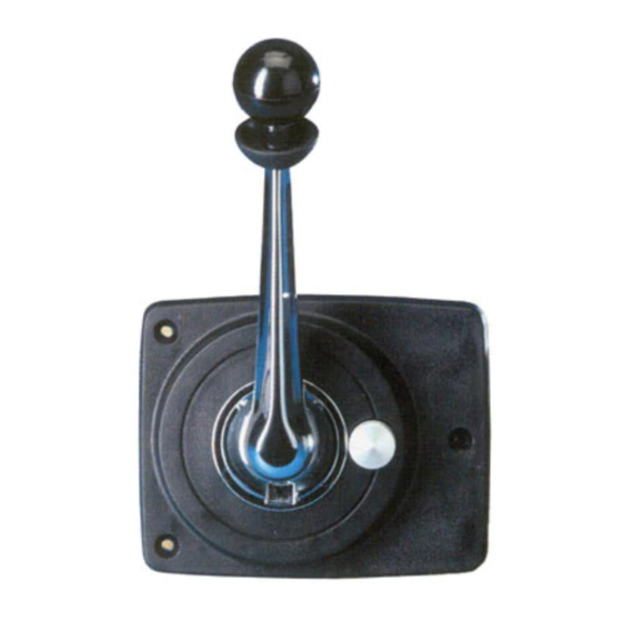
Introduction The Morse MV-2 Control is designed to provide convenient, one hand, single lever operation of shift and throttle for most popular outboards, inboard/outdrives and inboards equipped with hydraulic reverse gears. A safety feature of the MV-2 is a Neutral Locking Hand Lever. It can only be dis- engaged from Neutral by raising the collar under the ball knob. - Page 4 R.H. CABLE FROM FRONT-PULL TO GO FORWARD L.H. CABLE FROM REAR-PUSH TO GO FORWARD R.H. CABLE FROM REAR-PUSH TO GO FORWARD L.H. CABLE FROM FRONT-PULL TO GO FORWARD R.H. CABLE FROM FRONT-PUSH TO GO FORWARD L.H. CABLE FROM REAR-PULL TO GO FORWARD Reversing Throttle Action Check the carburetor throttle arm to determine whether Push or Pull is required WARNING...
-
Page 5: Mounting Location
CAUTION Should it be necessary to re- move the hanger plate from the back of the control, DO NOT remove the two (2) recessed screws which retain the back of the Gear Unit Assembly. Disas- sembly of the gear unit could result in loss of inner compo- nents and incorrect re-assem- bly. - Page 6 NOTICE Maximum thickness panel is 3/4 inches. Control will install more easily in a 1/2 inch thick panel. Shift Cable Connection Insert shift cable through opening at rear of hanger assembly in line with the shift arm pivot attachment holes and lock cable anchor groove in the hanger CAUTION slot.
-
Page 7: Neutral Safety Switch
Throttle Cable Connection With the opening in the swivel bracket nearest to the cable entry end of the control, insert the throttle cable through the opening in the swivel bracket and secure the cable anchor groove in the swivel bracket slot. Screw the pivot on to cable rod end and allow cable rod threads to protrude through the pivot 3/16 inch minimum. -
Page 8: Engine Connection
Engine Connection Connect the shift and throttle cables to the shift and throttle levers at the en- gine, following the instructions provided with the appropriate connection kit or CAUTION with the engine. Over jamming the transmis- sion stop at either at either end Shift cable must connect so that the “FORWARD”... -
Page 9: Preliminary Check
Preliminary Check Check to make sure there is no interference with either the hand lever or the control mechanism movement. NOTICE Place the control handle lever in the Neutral position, then grasp the button To operate the hand lever, it is next to the hand lever hub. -
Page 10: Replacement Kits
Hand Lever Assembly, Complete with knob and Set screw #306494 Interlock Ring #307365 Ball Knob Set - One Red, One black - #CA68287 USA Sales/Support Overseas Sales/Support Teleflex Marine Teleflex Marine Nuetral Safety Switch Kit #300928 640 North Lewis Road International Sales and...
Need help?
Do you have a question about the MV-2 Series and is the answer not in the manual?
Questions and answers