Table of Contents
Advertisement
Quick Links
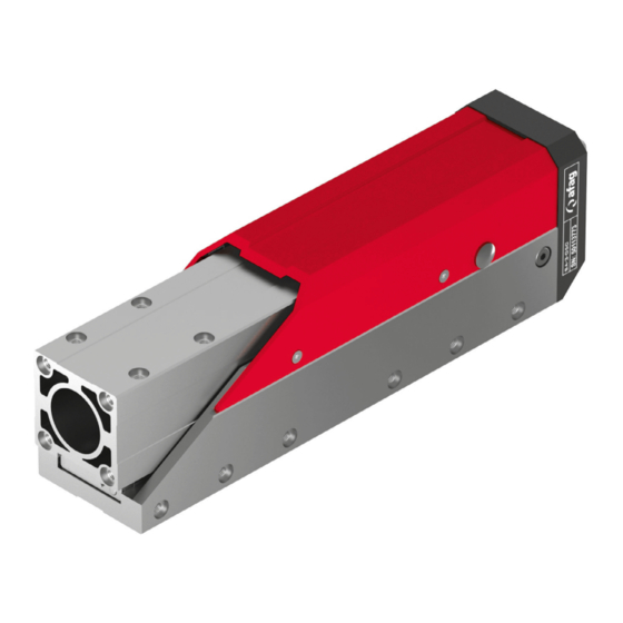
Assembly and operating instructions
Telescope spindle axis
Translation of the Original Assembly Instructions EN
SA-1-050
Order no.: 50249011
SA-1-050-FL
Order no.: 50471882
SA-1-100
Order no.: 50249013
SA-1-100-FL
Order no.: 50471883
SA-1-150
Order no.: 50249014
SA-1-150-FL
Order no.: 50471884
Assembly instructions EN
SA-1
SA-1 I SA-1-FL
Edition 01/2021
I
SA-1-FL
Rev. 3.5
1–52
Advertisement
Chapters
Table of Contents

Related Manuals for Afag SA-1 Series


Summary of Contents for Afag SA-1 Series
- Page 1 Assembly and operating instructions Telescope spindle axis SA-1 SA-1-FL Translation of the Original Assembly Instructions EN SA-1-050 Order no.: 50249011 SA-1-050-FL Order no.: 50471882 SA-1-100 Order no.: 50249013 SA-1-100-FL Order no.: 50471883 SA-1-150 Order no.: 50249014 ...
- Page 2 Your Afag team © Subject to modifications The modules have been designed by Afag Automation AG according to the state of the art. Due to the constant technical development and improvement of our products, we reserve the right to make technical changes at any time.
-
Page 3: Table Of Contents
Table of contents Table of contents General ........................5 Contents and purpose of these assembly instructions ......... 5 Explanation of symbols................. 5 Additional symbols ..................6 Applicable documents .................. 7 Warranty ....................... 7 Liability ......................7 Safety instructions ....................8 General ...................... - Page 4 Motor layout ....................27 6.3.1 Arrangement options ................27 6.3.2 Adjusting the motor position ..............28 6.3.3 Motor control ..................29 Afag standard controllers ................30 6.4.1 SE-48 Controller ................... 30 6.4.2 SE-Power for control cabinet mounting..........32 6.4.3 Servo controller ..................34 Programming of the telescope spindle axis..........
-
Page 5: General
General General 1.1 Contents and purpose of these assembly instructions These assembly instructions contain important information on assembly, commissioning, functioning and maintenance of the telescope spindle axis SA- 1 and SA-1-FL to ensure safe and efficient handling and operation. Consistent compliance with these assembly instructions will ensure: ... -
Page 6: Additional Symbols
General This note contains important additional information as well as useful tips for safe, efficient and trouble-free operation of the module. Further warning signs: Where applicable, the following standardised symbols are used in this manual to point out the various potential health risks. Warning - Dangerous electrical voltage. -
Page 7: Applicable Documents
This does also apply to defective accessories and wear parts. Normal wear and tear are excluded from the warranty. The warranty covers the replacement or repair of defective Afag parts. Further claims are excluded. The warranty shall expire in the following cases: ... -
Page 8: Safety Instructions
Safety instructions Safety instructions 2.1 General This chapter provides an overview of all important safety aspects to ensure safe and proper use of the telescope spindle axis and optimal protection of personnel. Safe handling and trouble-free operation of the telescope spindle axis requires knowledge of the basic safety regulations. -
Page 9: Obligations Of The Operator And The Personnel
the operating company shall be solely responsible for such damage, and Afag does not accept any liability for damages caused by improper use. 2.4 Obligations of the operator and the personnel 2.4.1... -
Page 10: Obligations Of The Personnel
Safety instructions 2.4.3 Obligations of the personnel All personnel working with the telescope spindle axis are required to: read and observe these assembly instructions, especially the chapter on safety, observe the occupational safety and accident prevention regulations, observe all safety and warning signs on the telescope spindle axis, ... -
Page 11: Personal Protective Equipment (Ppe)
2.7 Changes & modifications No changes may be made to the telescope spindle axis which have not been described in these assembly instructions or approved in writing by Afag Automation AG. Afag Automation AG accepts no liability for unauthorised changes or improper assembly, installation, commissioning, maintenance or repair work. -
Page 12: General Hazards / Residual Risks
Safety instructions 2.8 General hazards / residual risks Despite the safe design of the telescope spindle axis and the technical protective measures taken, there still remain residual risks that cannot be avoided and which present a non-obvious residual risk when operating the telescope spindle axis. -
Page 13: Mechanical Hazards
Safety instructions 2.8.1 Mechanical hazards CAUTION Risk of injuries by moving parts and unexpected movements! When operating the telescope spindle axis uncontrolled movements may occur which can cause personal injury or property damage. There is always a risk of injury by moving parts during normal operation. ... -
Page 14: Danger Due To High Temperatures
Safety instructions 2.8.4 Danger due to high temperatures CAUTION Danger of injury from hot surfaces. During continuous operation of the telescope spindle axis, the surface of the axis heats up. Before touching hot surfaces without protective gloves, make sure they have cooled down to ambient temperature. -
Page 15: Technical Data
Technical data Technical data 3.1 Dimension drawing SA-1 and SA-1-FL Fig. 1 Dimension drawing telescope spindle axis Assembly instructions EN SA-1 I SA-1-FL Edition 01/2021 Rev. 3.5 15–52 ... -
Page 16: Technical Data Sa-1 And Sa-1-Fl
Technical data 3.2 Technical data SA-1 and SA-1-FL 16 – 52 Assembly instructions EN SA-1 I SA-1-FL Edition 01/2021 Rev. 3.5 ... -
Page 17: Preferred Combinations Sa-1 And Sa-1-Fl
Technical data 3.3 Preferred combinations SA-1 and SA-1-FL AFAG accepts no liability for the attachment of third-party modules to the telescope spindle axis. Modules for attachment shall be selected to withstand full load operation of the telescope spindle axis and not exceed the payload. -
Page 18: Transport, Packaging And Storage
Transport, Packaging and Storage Transport, Packaging and Storage 4.1 Safety instructions for transport CAUTION Risk of injury when unpacking the telescope spindle axis! The telescope spindle axis can be moved back and forth when it is not fastened, causing crushing injuries to the fingers. ... -
Page 19: Transport
4.4 Packaging The telescope spindle axis is transported in the Afag Automation AG transport packaging. If no Afag packaging is used, the telescope spindle axis must be packed in such a way that it is protected against shocks and dust. -
Page 20: Structure And Description
Structure and description Structure and description 5.1 Structure telescope spindle axis Fig. 3 Structure of telescope spindle axis (example) 1. Base body 6. Coupling housing 2. Bracket 7. Servo motor 3. Linear guide 8. Holding brake 4. Ball screw axis 9. -
Page 21: Accessories
Structure and description The telescope spindle axis SA-1 and SA-1-FL is available in the following versions ( Chapter 3 “Technical data”). Type Nominal stroke SA-1-50 and SA-1-50-FL 50 mm SA-1-100 and SA-1-100-FL 100 mm SA-1-150 and SA-1-150-FL 150 mm 5.3 Accessories Designation Order Number... -
Page 22: Installation, Assembly & Setting
Installation, assembly & setting Installation, assembly & setting The system operator is responsible for the installation of the telescope spindle axis in a system! 6.1 Safety Instructions for Installation & Assembly The telescope spindle axis is an incomplete machine. For safe operation, the telescope spindle axes must be integrated into the safety concept of the system in which they are installed. -
Page 23: Assembly & Attachment
Installation, assembly & setting 6.2 Assembly & attachment The telescope spindle axis can be installed in any position. In the case of vertical installation, the servomotor must have a holding brake that prevents axle from falling when de-energised! The telescope spindle axis must be earthed when installed in a system! 6.2.1 Fastening the module The telescope spindle axis mounting holes (M4) are located on the back of the... -
Page 24: Attachment Grid And Centering Bushings
Installation, assembly & setting 6.2.3 Attachment grid and centering bushings Use the centring bushings included in the scope of delivery for positioning. Insert the centering bushings in two diagonally opposite holes of the attachment grid. SA-1 and SA-1 FL Base body Bracket Hole grid 30 x 30 mm... -
Page 25: Load On The Telescope Spindle Axis
Installation, assembly & setting 6.2.4 Load on the telescope spindle axis The following telescope spindle axis loads apply to assembly: Assembly instructions EN SA-1 I SA-1-FL Edition 01/2021 Rev. 3.5 25–52 ... -
Page 26: Load Diagrams
Installation, assembly & setting 6.2.5 Load diagrams 26 – 52 Assembly instructions EN SA-1 I SA-1-FL Edition 01/2021 Rev. 3.5 ... -
Page 27: Motor Layout
Installation, assembly & setting 6.3 Motor layout The motor arrangement can be either front, left, right or axial. Fig. 5 Possible arrangement of the servomotor 6.3.1 Arrangement options Motor RIGHT Motor AXIAL Fig. 6 Mounting the motor RIGHT / AXIAL 1. -
Page 28: Adjusting The Motor Position
Installation, assembly & setting 6.3.2 Adjusting the motor position Fig. 7 Adjusting the motor position 1. Cover 2. 1 x Screw M3x6 3. 4 x Screws M3x6 4. Housing Procedure for changing the position of the motor: 1. Switch off the controller of the module. 2. -
Page 29: Motor Control
Emergency Stop switch Signal 5 … 24 V DC Signal, PNP We recommend using the Afag standard cables specified in the accessories. The motor connectors can be rotated 180°. Proceed as described below. 1. Loosen the screws. 2. Rotate the motor connectors. -
Page 30: Afag Standard Controllers
Installation, assembly & setting 6.4 Afag standard controllers Afag Automation AG offers two different controllers for the SA telescope spindle axis (type SE-48). Further information on the control units can be found in the technical product catalogue ( Chapter “Controller”) or in the respective instructions on our website (www.afag.com). -
Page 31: Fig. 10 Dimensions - Controllers Se-48
Installation, assembly & setting Fig. 10 Dimensions - Controllers SE-48 Assembly instructions EN SA-1 I SA-1-FL Edition 01/2021 Rev. 3.5 31–52 ... -
Page 32: Se-Power For Control Cabinet Mounting
Installation, assembly & setting 6.4.2 SE-Power for control cabinet mounting Fig. 11 Overview table - SE-Power for control cabinet mounting 32 – 52 Assembly instructions EN SA-1 I SA-1-FL Edition 01/2021 Rev. 3.5 ... -
Page 33: Fig. 12 Installation - Se-Power For Control Cabinet Mounting
Installation, assembly & setting Fig. 12 Installation - SE-Power for control cabinet mounting Assembly instructions EN SA-1 I SA-1-FL Edition 01/2021 Rev. 3.5 33–52 ... -
Page 34: Servo Controller
Installation, assembly & setting 6.4.3 Servo controller 34 – 52 Assembly instructions EN SA-1 I SA-1-FL Edition 01/2021 Rev. 3.5 ... -
Page 35: Programming Of The Telescope Spindle Axis
Immediately replace a defective encoder or limit switch cable. When using an AFAG Se-Power controller, the information in the corresponding operating instructions must be observed. The associated operating instructions are additionally available on the AFAG website www.afag.com. -
Page 36: Commissioning
Commissioning Commissioning After connection, the telescope spindle axes are put into operation for the first time via the system controller. 7.1 Safety instructions for commissioning WARNING Risk of injury during commissioning due to incorrect programming! Incorrect programming can trigger uncontrolled movements of the telescope spindle axis, which can lead to serious injuries as well as damage to property. -
Page 37: Preparatory Activities For Commissioning
Commissioning 7.2 Preparatory activities for commissioning An insulation test must be carried out before the telescope spindle axis is put into operation! CAUTION Danger due to missing protective devices! Operating the telescope spindle axis without suitable safety devices can lead to considerable damage to property and injuries. -
Page 38: Setting Up & Retrofitting
Commissioning 7.4 Setting up & retrofitting CAUTION Risk of injury due to incorrect operation of the system! Incorrect operation during set-up work on the system can lead to unintentional start-up of the telescope spindle axis and cause injuries. Adjusting and maintenance work may only be carried out by qualified personnel. -
Page 39: Fault Elimination
Fault elimination Fault elimination 8.1 Safety instructions for troubleshooting WARNING Danger of injury due to faulty troubleshooting! Poorly performed troubleshooting work can lead to serious injuries and damage to property. Only use trained specialist personnel for troubleshooting. All work on the telescope spindle axis must be carried out with the power supply cut off! NOTICE Danger of material damage due to vibrations on the drive! -
Page 40: Fault Causes And Remedy
Carry out function check Motor disconnection Check motor cable Drive defective Have the drive replaced by AFAG Malfunction during operation Fault Possible cause Remedy: Control parameters incorrectly Readjust the parameters on the... -
Page 41: Maintenance And Repair
Maintenance and Repair Maintenance and Repair 9.1 General notes The following maintenance activities can ensure optimum operating condition of the telescope spindle axis. 9.2 Safety instructions for Maintenance and Repair WARNING Danger of injury due to improper maintenance! Improperly carried out maintenance activities can cause considerable damage to property and serious injury. -
Page 42: Maintenance Activities And Maintenance Intervals
Maintenance and Repair 9.3 Maintenance activities and maintenance intervals Observe the specified maintenance and care intervals. The intervals apply to normal operating conditions and are to be shortened accordingly for other conditions. Fig. 13 Telescope spindle axis 9.3.1 Overview of the maintenance points System Maintenance Interval... -
Page 43: Lubrication Of Spindle Gear
Maintenance and Repair NOTICE Risk of property damage if unsuitable lubricants are used! Certain lubricants with additives can cause damage to the linear unit. Lubricants with additives (e.g. MoS , Graphite or PTFE) must not be used for maintenance of the linear unit! 9.3.2 Lubrication of spindle gear The spindle gear must be lubricated every 4 million load changes (strokes). -
Page 44: Lubrication Of Linear Guide
Maintenance and Repair 9.3.3 Lubrication of linear guide The linear guide is initially lubricated with the special long-life grease on delivery. The linear guide must be lubricated every 10 million load changes (strokes). Fig. 15 Telescope spindle axis - grease nipple linear guide 1. -
Page 45: Further Maintenance
9.4 Spare parts and repair work Afag Automation AG offers a reliable repair service. Defective telescope spindle axis can be sent to AFAG for warranty repair within the warranty period. Damaged telescope spindle axis may only be replaced or repaired by Afag... -
Page 46: Decommissioning, Disassembly, Disposal
Decommissioning, disassembly, disposal 10 Decommissioning, disassembly, disposal The telescope spindle axis must be properly dismantled after use and disposed of in an environmentally friendly manner. 10.1 Safety instructions for decommissioning and disposal WARNING Risk of injury due to improper decommissioning and disposal! Improperly carried out activities can result in considerable material damage and serious injury. -
Page 47: Declaration Of Incorporation
The relevant technical documentation has been created according to Annex VII, Part B of the above- mentioned Directive. Authorised representative for compiling the technical documentation: Niklaus Röthlisberger, Product-Manager, Afag Automation AG, CH-4950 Huttwil, Germany Place/Date: Huttwil, 07.01.2020 Siegfried Egli Niklaus Röthlisberger... - Page 48 Index Index Operator ............10 Axes and channels ..........41 Packaging ............19 Personal protective equipment (PPE)....11 Decommissioning ..........46 Personnel qualifications ........10 Disposal ............. 46 Personnel requirements ........10 Protective clothing..........11 Explanation of symbols ........5 Protective gloves..........
- Page 49 List of figures List of figures Fig. 1 Dimension drawing telescope spindle axis ..................15 Fig. 2 Telescope spindle axis ........................18 Fig. 3 Structure of telescope spindle axis (example) ................20 Fig. 4 Mounting holes (M4) on the back of the housing ................23 Fig.
- Page 50 50 – 52 Assembly instructions EN SA-1 I SA-1-FL Edition 01/2021 Rev. 3.5 ...
- Page 51 Assembly instructions EN SA-1 I SA-1-FL Edition 01/2021 Rev. 3.5 51–52 ...
- Page 52 52 – 52 Assembly instructions EN SA-1 I SA-1-FL Edition 01/2021 Rev. 3.5 ...
Need help?
Do you have a question about the SA-1 Series and is the answer not in the manual?
Questions and answers