
Subscribe to Our Youtube Channel
Related Manuals for Afag Flipband 200

Summary of Contents for Afag Flipband 200
- Page 1 Flexible feed device Flipband 200 / Flipband 300 Operating and assembly manual Copyright by Afag GmbH...
- Page 2 Version of this documentation: BA_Flipband_200_300_R03.2_EN.docx Release: R03.2 Date: 08/07/2018 History version changes R03.0 Documentation of Flipband 200 and Flipband 300 R03.1 Changes of technical data regarding the maximal clockwise belt rotation length R03.2 Correction of order numbers Page 2 08/07/2018 R03.2...
-
Page 3: Table Of Contents
Belt operating mode, rotary switch "mode rpm" ..................23 Flip direction, "mode dir" rotary switch ....................24 Flipping operating mode, "mod" rotary switch..................25 4.4.1 Afag test mode ..........................26 Control profiles ....................27 Profiles for belt control ........................... 27 5.1.1 Belt direction and speed via an analog input ................ - Page 4 Maintenance instructions ................31 Ordering address: .................... 31 10 Disposal ......................31 Page 4 08/07/2018 R03.2...
-
Page 5: Safety Instructions
1 Safety instructions Explanation of symbols and notices Symbols: Installation and commissioning must be carried exclusively by qualified personal according to the operating manual. Please observe the following explanation of symbols and notices. They are classified according to danger levels and in according to ISO 3864-2. DANGER Identifies an imminently threatening danger. -
Page 6: Electrical Connection
Principle safety information This operating manual serves as a basis for safe use and operation of the flexible Flipband feed device. This operating manual, particularly the safety information, must be observe by all persons working on or with the Flipband. In addition, the rules and regulations for accident prevention for the respective place of use must be observed. -
Page 7: Danger Areas
1.1.2 Danger areas NOTICE The flexible supply devices from Afag are designed in accordance with the EC Machinery Directive, according to the state-of-the-art and generally recognized good engineering practices. Neverthe- less, the use can result in hazards to life and limb of the user or others and can cause damage to the Flipband or other property. -
Page 8: Obligations Of The Owner
Obligations of the owner The Flipband must be in a safe condition and used safely to ensure the safe operation. Consequently, the operating company is obligated to ensure that the following instruc- tions are complied with: Ensure that the Flipband is operated exclusively by authorized personnel. Forbid unsafe and/or dangerous work procedures. - Page 9 NOTICE Reasonably foreseeable misuse, which could pose a danger to the user, third parties or the Flipband, includes: a) The feed of components that deviates from the size and geome- try that deviates specified for the Flipband. b) Operating the Flipband beyond the physical operating limits as described in the Chapter “Commissioning/Operation”...
-
Page 10: Description Of The Device
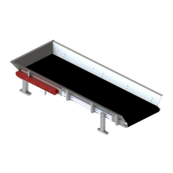
2 Description of the device General information The Flipband consists of a conveyor belt and the integrated flip unit, with a control unit integrated in the flip unit. The control unit is designed for configuration of the possible operating modes. The advantages of the Flipband system are: Configuration of an individual system, adapted to the respective application Fully-integrated embedded system... -
Page 11: Technical Data
Technical Data Figure 1: Flip belt dimension sheet Table 1: Technical Data Description Unit Flipband 200 Flipband 300 [mm] [mm] [mm] [mm] [mm] ~1044 ~1044 Dimensions [mm] [mm] [mm] 1000 1000 [mm] [mm] 40x40 40x40 Max. part size [mm x mm] Max. -
Page 12: Transport
Transport WARNING Incorrect use of transport equipment (industrial trucks, hall crane, aids, slings, etc.) can result in crushing and other injuries. Re- quired conduct: ▪ Observe and adhere to the transport and assembly instruc- tions ▪ Use transport equipment appropriately CAUTION The Flipband must only be lifted by the base body for transport. -
Page 13: Assembly Of The Unit
Fault-free operation cannot be guaranteed if it this is disregarded. 2.5.1 Hole pattern for assembly Figure 2: Hole pattern on assembly level Description Flipband 200 Flipband 300 Hole distance X in [mm] Hole distance L remains the same for both types R03.2... -
Page 14: Assembly Of The 4 Holders On The Flipband
2.5.2 Assembly of the 4 holders on the Flipband 2.5.2.1 Assembly of the two front holders in the slot of the aluminum profile Figure 3: Insertion of T-nuts and slotted nuts, of the front holder Proceed as follows to fasten the 2 holders on the slotted profile: Slide one of the two accompanying slotted nuts into the upper slot at the desired posi- tion and secure one of the double T-nuts at the desired position in the lower slot with a setscrew. - Page 15 Figure 4: Assembly of the two front holders in the slot of the aluminum profile Now the holder is fastened with the supplied M4x20 (10.9) cylinder head screws and the corresponding spring washers on the T-block and slotted nut. NOTICE Observe the following: Maximum torque: 3.5Nm 2.5.2.2 Assembly of the holder for the gear cover...
- Page 16 NOTICE Observe the following: Maximum torque: 1.8Nm 2.5.2.3 Assembly of the holder opposite the gear cover Figure 6: Assembly of the holder opposite the gear cover The last holder is fastened in the same manner as the first two, with M4x20 (10.9) and the corresponding spring washers.
-
Page 17: Assembly Of The Flipband On The Base Plate
2.5.3 Assembly of the Flipband on the base plate Figure 7: Assembly of the Flipband on the base plate The belt is then mounted with 8 M5 cylinder head screws on the base plate. (These screws are not included in the scope of supply) NOTICE Observe the following: Base plate executed as steel plate ≥... -
Page 18: Connection Of The Unit
Connection of the unit The actuators of the Flipband are connected by means of the 16-pin socket on the underside. Use the supplied connection cable with corresponding plug connector for this purpose. Figure 8: Connection of the unit Power supply WARNING ▪... -
Page 19: Signal Designation
Signal designation The Sub-D interface of the Flipband has three analogue inputs, four digital inputs and three digital outputs. The supply voltage is fed via the same supply line. The supply to the control unit via the control voltage is separate from the supply of the motors via the load voltage. -
Page 20: Cable Signal Assignment
Cable signal assignment Figure 9: Circuit diagram Figure 11: Conductor cross-section Figure 10: Plug pin assignment Page 20 08/07/2018 R03.2... -
Page 21: Referencing
3 Referencing Once the supply voltage is connected to the logic and load feed, the belt begins to reference. This means that it starts the search process for the center position of the flip shafts. This process is mandatory in order to perform end positioning of the shafts after each flip process. -
Page 22: Adjustment Modes
4 Adjustment modes The Flipband supports different control profiles. The profile is selected via rotary switch on the Flipband. The adjustment options of individual rotary switches are listed below. Belt direction, "mode dir" rotary switch NOTICE Observe adjustment constellations! Only turn the switch to Setting 4 in mode dir if Setting 4 is also se- lected for mode rpm. -
Page 23: Belt Operating Mode, Rotary Switch "Mode Rpm
Belt operating mode, rotary switch "mode rpm" NOTICE Observe adjustment constellations! Only turn the switch to Setting 4 in mode rpm if Setting 4 is also selected for mode dir. Examples for control, see 5.1 Profiles for belt control The different speed operating modes of the conveyor belt are listed below. Figure 13: Belt speed mode Table 4: Speed mode selection options Switch posi-... -
Page 24: Flip Direction, "Mode Dir" Rotary Switch
CAUTION If Mode 4 is selected with "man rpm", a 5V level must be connected to U before the supply voltage U is switched on. Other- A_Csp Logic wise, the belt starts up. Flip direction, "mode dir" rotary switch The different rotating directions of the flip shafts are listed below. Figure 14: Flip direction mode The rotating direction of the flip shafts is permanently adjusted via the rotary switch. -
Page 25: Flipping Operating Mode, "Mod" Rotary Switch
Table 6: Flip configuration selection options Switch Description Flip mode position Test program for diagnosis (Afag test mode) See 4.4.1 Afag test mode. Rising flank at U starts the flipping pro- Flip duration Analog D_Fon cess. If an additional rising flank is recognized, A_Fdur the flip duration starts from nine. -
Page 26: Afag Test Mode
(PT1)) 4.4.1 Afag test mode The Afag test mode is intended for checking the toothed belt tension of the flipper shafts. This check must only be started with the belt disassembled, because the flipper must move freely during the check. The minimum current required to move the respec- tive flipper is evaluated. -
Page 27: Control Profiles
5 Control profiles The combination of rotary switches described in the previous chapter indicates the different control profiles. One of these profiles should be selected depending on the required flexibility and available control options. Profiles for belt control 5.1.1 Belt direction and speed via an analog input In order to control the belt direction and belt speed with input U , the direction A_Csp... -
Page 28: Profiles Of The Flipper Control
change from a level of 0V to a voltage value (depending on selection of the desired belt speed) at U , the belt is started. A_Csp NOTICE If the input U does not have a fixed level (open end), the belt D_Cdir runs counterclockwise. -
Page 29: Led Displays
positioning is carried out after the time has expired if there is a High signal at U DO_rdy to signal that the belt is ready to flip again. Define flip duration and flipping speed dynamically mode In order to define the flipping speed and flip duration manually, but define the flip du- ration dynamically via the analogue inputs U and U the flip mode switch (mod) -
Page 30: Acknowledge Error
Table 7: Flipband LED display Message Error occurred during operation Initialization Afag test mode 7 Acknowledge error If an error occurs during operation, it must be acknowledged with the "check" button or via the connection . If there is still an error pending after the error has been D_AckErr confirmed, the Flipband switches to error mode. - Page 31 However, if repairs or maintenance work are necessary, please contact the manufacturer of the Flipband. 9 Ordering address: Germany: Switzerland: Afag GmbH Afag Automation AG Wernher-von-Braun-Straße 1 Feeding technology D – 92224 Amberg Fiechtenstrasse 32 CH – 4950 Huttwil Tel.: ++49 (0) 96 21 / 65 0 27-0 Fax: ++49 (0) 96 21 / 65 0 27-490 Tel.: ++41 (0) 62 / 959 86 86...
- Page 32 Page 32 08/07/2018 R03.2...
Need help?
Do you have a question about the Flipband 200 and is the answer not in the manual?
Questions and answers