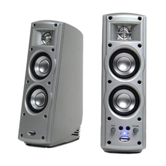
Klipsch ProMedia Ultra 2.0 Replacement Manual
Replacement of the bass and volume controls
Hide thumbs
Also See for ProMedia Ultra 2.0:
- Owner's manual (20 pages) ,
- User manual (4 pages) ,
- Brochure (20 pages)
Advertisement
Replacement of the bass and volume controls of the Klipsch ProMedia
Ultra 2.0 speakers
Overview:
Both the bass and volume controls use a linear taper, 50K resistance potentiometer. The bass control is
single-gang, the volume control is double-gang + rotary switch. This document describes replacement of
both potentionmeters with new potentiometers and a seperate toggle switch that takes the position of the
power LED on the faceplate. To accommodate the new components the faceplate is modified.
Components used:
- Jaycar RP8516 (bass pot – 9mm single-gang linear 50K pot)
- Jaycar RP8710 (volume pot – 9mm double-gang linear 50K pot)
- Jaycar HK7734 (bass and volume knobs)
- NKK G12JPF (illuminated toggle switch)
Tools/other used:
- Screwdriver (say 6mm Phillips and 2mm flat, or thereabouts)
- Soldering iron, solder, wire (thin as possible)
- Hot glue gun
- Drill, drill bits 2.5-12mm, spade bit 10mm
- Spanner/wrench 10mm
- Light sandpaper
Initial disassembly:
1. Turn the speakers off, remove them from mains power, unplug all cables from the main speaker.
2. Remove it's dust cover.
3. Remove the ten screws that secure the faceplate.
4. Remove the faceplate.
Note: The faceplate is leashed to the main body by wiring. It is best to lay the unit on it's side from here on.
5. Remove the three pieces of packing material.
6. Remove the glue from the power LED and free it from the faceplate.
7. Remove the glue that anchors the speaker wiring to body.
8. Remove the glue from the body where it secures the main PCB.
9. Remove the tape from the body where is secures the main PCB.
10. Remove the two screws that secure the rear-mounted PCB.
11. Slide the main PCB out from the body.
Note: Use a pen or similar object to push the main PCB out from behind.
Advertisement
Table of Contents

Subscribe to Our Youtube Channel
Related Manuals for Klipsch ProMedia Ultra 2.0


Summary of Contents for Klipsch ProMedia Ultra 2.0
- Page 1 Replacement of the bass and volume controls of the Klipsch ProMedia Ultra 2.0 speakers Overview: Both the bass and volume controls use a linear taper, 50K resistance potentiometer. The bass control is single-gang, the volume control is double-gang + rotary switch. This document describes replacement of both potentionmeters with new potentiometers and a seperate toggle switch that takes the position of the power LED on the faceplate.
- Page 2 Potentiometer removal: 1. Remove the knobs from the bass and volume potentiometers. 2. Peel back the adhesive pads from the PCB, exposing the solder points of the potentiometers and their bracing.
- Page 3 3. Unscrew the nuts and remove the washers from the bass and volume potentiometers. Note: Steps 3,4 apply to the bass potentiometer. 3. Apply the soldering iron to the two brace solders and use leverage to free it from the PCB. Note: Either of the following...
- Page 4 Reference: Switch contacts in blue, pots as red/green/purple, bracing mounts as yellow. Note: Because these potentiometers will be mounted contacts away from the board, you will need to swap the red/purple sides to maintain a clockwise action. 1. Solder new wiring to main PCB board. Note: Unlike these pictures, make sure the wiring is kept as low and backward as possible to allow space for the new potentiometers.
- Page 5 3. Solder wiring to potentiometers. 4. Attach potentiometers to frames. Note: In this case I added some hot melt glue between the frames and potentiometers to prevent slipping. 5. Solder frames to main PCB. New switch: 1. Sever the LED wiring. You could new wire for length, but if you cut close to the LED it shouldn't be necessary.
- Page 6 1. Cover the speakers to prevent plastic from entering them. 2. Start with the bass and volume holes. Find the drill bit the size of the holes, then use the next larger bit to enlarge them. Gradually step up the bit size until the holes are large enough to accommodate the new knobs. The bits will generally self-centre, and the plastic is thin enough to hand drill.
- Page 7 the faceplate and hold it there until the glue cools. Finished product – before and after...
Need help?
Do you have a question about the ProMedia Ultra 2.0 and is the answer not in the manual?
Questions and answers