Opera 6000 Series Operation Manual
Digital gas monitor/controller
Hide thumbs
Also See for 6000 Series:
- Operation manual (27 pages) ,
- Installation manuallines (2 pages) ,
- Operation manual (22 pages)
Table of Contents
Advertisement
Advertisement
Table of Contents

Subscribe to Our Youtube Channel
Related Manuals for Opera 6000 Series


Summary of Contents for Opera 6000 Series
- Page 1 Version 6.2 Digital Gas Monitor/Controller OPERATION MANUAL...
-
Page 2: Table Of Contents
TABLE OF CONTENTS General Description Applications Features Specifications User Interface Model Selection Guide Installation Monitor Placement Wiring Installation Check List Operation Screen Display Default Settings Changing Settings List of Settings Sequence of Operation Network Configuration Using CAN Network, Central Controller Using CAN Network No Central Controller Defaults Configuration Creating Zones or Groups... -
Page 3: General Description
MS/TP cable to any monitor or 6000 controller on the CAN network. The gas readings from all the monitors will display on the BMS and the BMS can over-ride output relays on the monitor it is connected to. 6000 Series Digital Gas Monitor/Controller... -
Page 4: Applications
For indoor use • Flame resistant Polycarbonate ABS enclosure rated UL94 V0, 5VB, and 5VA • Standards. Listed to CSA C22.2. no. 205-17. Conforms to CSA C22.2 61010-1. • Analogue 4-20 ma or 2-10v (model 6000-A) 6000 Series Digital Gas Monitor/Controller... -
Page 5: User Interface
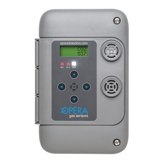
• Pollution degree 2 • Installation catagory II • Altitude 2000 m • Humidity max 80% rh. 80% to temperatures up to 31 ºC 88 ºF, decreasing linearity to 50% rh at 40 ºC (104 ºF) 1.4 User Interface: • Back lit LCD display shows gas concentration, user settings, calibration controls •... -
Page 6: Model Selection Guide
Example: Monitor for CO + NO 6002-14-B 6002-14-A Gas Type Gas type Gas Type Gas type (see chart) if second (see chart) if second sensor sensor installed installed Controller with Sensor(s) inside 55-xx Gas Type (see chart) Sensor Replacement Module 6000 Series Digital Gas Monitor/Controller... - Page 7 Gas Type Range Controller only, no sensor Ammonia 0-250 ppm Argon (O depletion) 0-50% O Carbon dioxide (air quality) 15-2000 0-2000 ppm Carbon dioxide (compressed) 15-5000 0-5000 ppm Carbon Monoxide 0-100 ppm Carbon Monoxide 02-250 0-250 ppm CO nil H Carbon Monoxide nil H effect 02nilH2...
-
Page 8: Installation
3 to 5 feet (1 to 2 meters) from the floor when the ceiling height is 7 to 10 feet. If the ceiling height is higher than 10 feet, example- for heavy equipment, the carbon monoxide monitors are installed 6000 Series Digital Gas Monitor/Controller... - Page 9 3. Heavier than air and will concentrate near the floor; - HFCs, HCFCs, propane, chlorine, most organic vapors (consult Opera). Install 1-2 feet (30cm to 50cm) from floor. For all types of monitors avoid drafts, obstacles, aerosols, silicones. Place sensors in the center of its coverage area as much as possible.
- Page 10 120/24 Vac network High (H) 5 Va for to other Low (L) each unit units Shield Independant (on 1rst unit only) Circuit 120 Vac To magnetic starter coil or Supply control relay coil for ventilation 6000 Series Digital Gas Monitor/Controller...
-
Page 11: Wiring
3.2.2 Wiring Model 6000-B End of line jumper CAN bus Down = Off Up for first and last unit on cable EOL BACnet BACnet Relay 1 Relay 2 Binary MSTP NO COM NO COM input network to limit – switch see 4.4 #32 Shield (no connect) -
Page 12: Installation Check List
EOL jumper is off (down) if it is in the middle. Monitor/controller addresses can be in any location on the chain. 7. Power on the units. They will display the gas type and reading. To verify if monitors are communicating correctly, change setting 6000 Series Digital Gas Monitor/Controller... - Page 13 1 on that unit and all of the other units on the network. See section 5 to set up a configuration for multiple zones. For assistance contact Opera Inc. (see back cover for contact info) Magnetic...
-
Page 14: Operation
Then click again to increase time from 5 to 60 minutes. This activates alarm 1 (or 2, and 3 per setting 69) and sends alarm transmit messages (settings 9-17) to other monitor on the CAN 6000 Series Digital Gas Monitor/Controller... -
Page 15: Default Settings
network. The unit will return to automatic operation after the time runs down. To cancel manual mode press ↓ several times to reduce time left to run. It will take a few seconds to stop. “M” also displays when auto-cycle is on. See setting 73. T indicates alarm 1 on due to high ambient temperature (setting 51). -
Page 16: List Of Settings
Alarm 2 transmit message, CAN 0-255 network A2Tx Alarm 2 transmit message, CAN 0-255 network A3Tx Alarm 3 transmit message, CAN 0-255 network A3Tx Alarm 3 transmit message, CAN 0-255 network A3Tx Alarm 3 transmit message, CAN 0-255 network 6000 Series Digital Gas Monitor/Controller... - Page 17 4.4 List of Settings Sensor B (lower socket) settings Name Description Range Default AL1-B Alarm 1 threshold, activates by sensor relay 1 A1Del Alarm 1 Delay on (seconds) 0-999 A1Off Alarm 1 Delay off (seconds) 0-999 AL2-B Alarm 2 threshold, activates by sensor relay 2 A2Del...
- Page 18 2 = BACnet communication enabled and display all sensors on CAN network BACnet MAC address BACnet baud rate 0/1/2/3 0 = 9600 1 = 19200 2 = 38400 3 = 76800 Keyboard lock, blocks access to options 6000 Series Digital Gas Monitor/Controller...
- Page 19 Name Description Range Default TMod Temperature modify/calibrate -9/+9 ºC ATHi High temperature alarm limit used 0-99 ºC for summer ventilation. Alarm 1 is 0-210 ºF activated when temperature exceeds option. Temp setting 72 deg C/ F will auto convert Warm up delay disables alarms, seconds 0-255 BACnet maximum MAC address when 0-127...
- Page 20 Automatic cycle timer Alarm 1 00C = total Cycle time in minutes Cycle 0-255 00/00 Press right arrow 00R = Run time in minutes Sensor module A age in days Press enter to display Sensor B 6000 Series Digital Gas Monitor/Controller...
-
Page 21: Sequence Of Operation
Name Description Range Default Variable Speed Drive logic Analogue output A Combines analogue outputs over CAN bus. See options 60-66 0= highest reading wins VSD A 1= sensor readings are averaged 0/1/2 2= auto ramping increases analogue output by one-minute intervals on alarm 1 and decreases when below alarm. - Page 22 LED strobe flasher will start (if enabled; setting 45), a 3 will appear in the bottom left corner of the display, and the Alarm 3 Transmit message (default 3) will be sent to other sensors or controllers. They can be silenced by pressing any button. 6000 Series Digital Gas Monitor/Controller...
- Page 23 13. When the gas concentration drops below the Alarm 3 set point for longer than the Alarm 3 Delay-Off setting then the audible alarm and strobe flasher will stop and the Alarm 3 Transmit message will stop being sent on the CAN network. 14.
-
Page 24: Network Configuration
6100 Relay Expansion Unit which has four additional relays. Zone 1 60xx 60xx 60xx 60xx Controller 6000 24 Vac; 2 conductor 18-20 AUG CAN; 2 conductor shielded 22-24 AUG Zone 2 60xx 60xx 60xx 60xx 6000 Series Digital Gas Monitor/Controller... -
Page 25: Using Can Network No Central Controller
5.2 Using CAN Network with No Central Controller (master/slave operation) One of the 60XX series monitors can be used as the controller. It can activate the ventilation for all the sensors, or a group. The use of a dedicated controller is optional; - to add a display in some specific location, such as before entering a mechanical room or to interface with several fan starters located in one place. -
Page 26: Defaults Configuration
(setting 36, 37) on the network, sent by other sensors. If more than 2 relays are needed, add a model 6100 Relay Expansion Unit which has 4 additional relays. It can be installed anywhere on the CAN network. 6000 Series Digital Gas Monitor/Controller... - Page 27 A model 6000 basic controller has no sensors on board so the relays will only activate if it sees it’s receive codes on the network. The 6000 controller could control two zones via its two relays. When no controller is used, the master monitor(s) needs to be a member of the group it is controlling.
-
Page 28: Maintenance Guide
5. Adjust gas reading to zero with the ↑ and ↓ buttons 6. Press ↑ and ← at the same time to save. 7. Press → The display will show SAS (sensor A span) and the current gas reading 6000 Series Digital Gas Monitor/Controller... - Page 29 4. Remove span gas mix and supply air. Sensor will return to zero. 5. If sensor does not return to zero, it needs replacement For assistance contact Opera Inc. (see back cover for contact info) 6.0 Maintenance Guide...
-
Page 30: Bacnet Network Configuration
ZZ = ID of device that received token. Setting 70 Device ID 4,194,303 60,000+BMA Ventilation Controlled by BACnet Building Automation 120 Vac 24 Vac Transformer for sensors only. Do not use 24 Vac from BMS 6000 Series Digital Gas Monitor/Controller... - Page 31 Object Table Type and Instance Object Name Object Property Parameter gas reading 1 Present value (R) Gas reading local sensor A gas reading 2 Present value (R) Gas reading local sensor B Ambient temperature Present value (R) Temperature in celsius BI 0 Input 1 Present value (R)
- Page 32 697 Meloche St Dorval, Quebec Canada H9P2S4 514-556-3013 info@detecteursopera.com www.operadetectors.com...
Need help?
Do you have a question about the 6000 Series and is the answer not in the manual?
Questions and answers