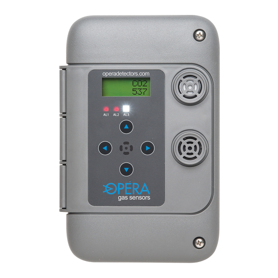
Opera 6000 series Operation Manual
Digital gas detector/controller
Hide thumbs
Also See for 6000 series:
- Operation manual (32 pages) ,
- Installation manuallines (2 pages) ,
- Operation manual (22 pages)
Table of Contents
Advertisement
Advertisement
Table of Contents

Related Manuals for Opera 6000 series


Summary of Contents for Opera 6000 series
- Page 1 Version 005.00 Digital Gas Detector/Controller OperatiOn Manual...
-
Page 2: Table Of Contents
Default Settings Changing Settings List of Settings Network Configuration Using CAN Network, Central Controller Using CAN Network No Central Controller Defaults Configuration Creating Zones or Groups Addresses Output Relays Maintenance Guide Calibration Procedure BACnet Network Configuration 6000 Series Digital Gas Detector/Controller... -
Page 3: General Description
1.2 Features: • Stand-alone operation with 1 or 2 adjustable alarm relays, indicators and strobe • BACnet Laboratory (BTL) listed Smart Sensor, up to 76,800 baud • BACnet MS/TP RS485 interface • CAN network interface for master-slave operation or central control via model 6000 controller. • Pre-calibrated plug-and-play sensor modules avoid the need to recalibrate when upgrading expired sensors. • Impact resistant, water resistant enclosure, with top wire entry and drip proof wire guide. 6000 Series Digital Gas Detector/Controller... -
Page 4: Specifications
Specifications • Supply 24 vac 50/60 hz (17-28 vac) 0.21 amps, 5 va • Relays (1 or 2) SPDT, 5 amp @ 125 vac, non-inductive On delay; 0-999 seconds (16 minutes) Off delay; 0-999 seconds (16 minutes) • Operating temperature -20 ºC to 40 ºC (-4 ºF to 104 ºF) • For indoor use • Flame resistant Polycarbonate ABS enclosure rated UL94 V0, 5VB, and 5VA • Standards. Conforms to UL61010-1, CSA C22.2 61010-1-12, ANSI/ISA 61010-1, CSA C22.2 no. 205-12 • Analogue 4-20 ma or 2-10v (model 6000-A) • Pollution degree 2 • Installation catagory II • Altitude 2000 m • Humidity max 80% rh. 80% to temperatures up to 31 ºC 88 ºF, decreasing linearity to 50% rh at 40 ºC (104 ºF) 1.4 user interface: •... -
Page 5: Model Selection Guide
Gas Type Gas type Gas Type Gas type (see chart) if second (see chart) if second sensor sensor installed installed Controller with Sensor(s) inside 55-xx Gas Type (see chart) Sensor Replacement Module example: 6002-14-B Detector for CO + nO 6000 Series Digital Gas Detector/Controller... - Page 6 Gas type Range Ammonia 0-250 ppm Argon (O depletion) 0-50% O Butane 0-50% LEL Carbon dioxide (AQ) 15-2000 0-2000 ppm Carbon dioxide (refrigerant) 15-5000 0-5000 ppm Carbon Monoxide 0-100 ppm Carbon Monoxide 02-250 0-250 ppm CO nilH Carbon Monoxide, nilH 02nilH2 0-100 ppm Chlorine 0-10 ppm (OH) Ethylene glycol 0-50% LEL Ethanol 0-50% LEL HCFCs...
-
Page 7: Installation
2. Similar density to air and will be diluted in air equally at all levels; - carbon monoxide, nitrogen dioxide, hydrogen sulfide, oxygen, carbon dioxide. Install from 3 feet (1 meter) off floor to one half of the ceiling height. For vehicle emissions carbon monoxide detectors combined with nitrogen dioxide detectors are installed at 3 to 5 feet (1 to 2 meters) from the floor when the ceiling is 7 to 10 feet high. If the ceiling height is higher than 10 feet, for example 6000 Series Digital Gas Detector/Controller... - Page 8 3. Heavier than air and will concentrate near the floor; - HFCs, HCFCs, propane, chlorine, most organic vapors (consult Opera), butane. Install 1-3 feet (30cm to 1 meter) from floor. For all types of sensors avoid drafts, obstacles, aerosols, silicones. Place sensors in the center of its coverage area as much as possible.
- Page 9 To Other Transformer Detectors 120/24 Vac network High 5 Va for each unit Shield Independant (on 1rst unit only) Circuit 120 Vac 24 Vac To magnetic starter coil or control relay coil for ventilation 120 Vac 6000 Series Digital Gas Detector/Controller...
-
Page 10: Wiring
3.2.2 Wiring Model 6000-B EOL CAN EOL BACnet BACnet Binary Relay 1 Relay 2 MSTP NO COM NO COM input network to limit – switch Shield (no connect) To Other Transformer Detectors 120/24 Vac network High 5 Va for each unit Shield Independant (on 1rst unit only) -
Page 11: Installation Check List
Ensure its EOL jumper is off (down) if it is in the middle. Sensor/controller addresses can be in any location on the chain. 7. Power on the units. They will display the gas type and reading. To verify if sensors are communicating correctly, change setting 6000 Series Digital Gas Detector/Controller... - Page 12 8. To further test communication, press and hold the up button on a sensor for 5 seconds to start manual mode (5 minutes). This will close the relay 1 on that unit and all of the other units on the network. See section 5 to set up a configuration for multiple zones. For assistance contact Opera Inc. (see back cover for contact info) Magnetic Starter Fan Power...
-
Page 13: Operation
From the home screen, press and hold ↑ for 5 seconds to start. Then click again to increase time from 5 to 60 minutes. This activates alarm 1 (or 2, and 3 per setting 69) and sends alarm 6000 Series Digital Gas Detector/Controller... -
Page 14: Default Settings
transmit messages (settings 9-17) to other sensors on the CAN network. The unit will return to automatic operation after the time runs down. To cancel manual mode press ↓ several times to reduce time left to run. It will take a few seconds to stop. T indicates alarm 1 on due to high ambient temperature (setting 51). Useful for summer ventilation. 4.2 Default Settings User settings are factory pre-loaded with default values to facilitate set up and can be changed at any time. - Page 15 Alarm 2 transmit message, CAN 0-255 network A2Tx Alarm 2 transmit message, CAN 0-255 network A3Tx Alarm 3 transmit message, CAN 0-255 network A3Tx Alarm 3 transmit message, CAN 0-255 network A3Tx Alarm 3 transmit message, CAN 0-255 network 6000 Series Digital Gas Detector/Controller...
-
Page 16: List Of Settings
4.4 list of Settings Sensor B (lower socket) settings Name Description Range Default AL1-B Alarm 1 threshold, activates by sensor relay 1 A1Del Alarm 1 Delay on (seconds) 0-999 A1Off Alarm 1 Delay off (seconds) 0-999 AL2-B Alarm 2 threshold, activates by sensor relay 2 A2Del Alarm 2 Delay on (seconds) 0-999 A2Off Alarm 2 Delay off (seconds) 0-999... - Page 17 Local audio alarm enable on alarm 3 BACnet MSTP mode select 0/1/2 0 = BACnet communication disabled 1 = BACnet communication enabled 2 = BACnet communication enabled and display all sensors on CAN network BACnet MAC address 6000 Series Digital Gas Detector/Controller...
- Page 18 Name Description Range Default BACnet baud rate 0/1/2/3 0 = 9600 1 = 19200 2 = 38400 3 = 76800 Keyboard lock TMod Temperature modify/calibrate -9/+9 ºC ATHi High temperature alarm limit used 0-99 ºC for summer ventilation. Alarm 1 is activated when temperature exceeds option. ºC Warm up delay disables alarms, seconds 0-255 BACnet maximum MAC address when 0-127...
- Page 19 0 and 3000 feet at rate 1 Manual mode activates alarms 1, 1+2 or 1+2+3. See screen display section. Bacnet device instance replace 0-4,194, 60000 default 60,000 + BMA (setting 47) BACnet device instance replace default 6 6000 Series Digital Gas Detector/Controller...
-
Page 20: Network Configuration
5.0 Network Configuration 5.1 Using CAN Network with a Central Controller A model 6000 controller serves as the central connection point for the ventilation system. Model 60XX gas sensors transmit alarm commands to the central controller. A controller will display up to 32 sensors on the network (64 for dual units). It also displays their address, gas type, gas concentration, and alarm status for each. Two relays on board can be configured for different levels of gas or to operate different ventilation systems, zones or groups. If more than two relays are needed add a model 6100 Relay Expansion Unit which... -
Page 21: Using Can Network No Central Controller
Starters and air dampers are connected to the sensor closest to it in each zone. 60xx 60xx 60xx 60xx Zone 1 24 Vac; 2 conductor 18-20 AUG CAN; 2 conductor shielded 22-24 AUG 60xx 60xx 60xx 60xx Zone 2 6000 Series Digital Gas Detector/Controller... -
Page 22: Defaults Configuration
5.3 Default Configuration Sensors are shipped pre-loaded with default settings which can be changed in the field to suit the desired sequence with simple keypad input. When a sensor goes into alarm level 1, 2 or 3 it activates its relays and transmits a message to other sensors to activate their relays also. -
Page 23: Maintenance Guide
0.1 LPM to 0.5 LPM. The gas fitting to sensor should have a small outlet hole. If not, the pressure will increase and distort the reading (high). 5. Adjust gas reading to zero with the ↑ and ↓ buttons 6. Press ↑ and ← at the same time to save. 6000 Series Digital Gas Detector/Controller... - Page 24 Do not change the factory calibration constants in calibration mode as above. 4. Remove span gas mix and supply air. Sensor will return to zero. 5. If sensor does not return to zero, it needs replacement For assistance contact Opera Inc. (see back cover for contact info) 6.0 Maintenance Guide...
-
Page 25: Bacnet Network Configuration
YY = ID of device that received token. Setting 70 Device ID 4,194,304 60,000+BMA Ventilation Controlled by BACnet Building Automation 120 Vac 24 Vac Transformer for sensors only. Do not use 24 Vac from BMS 6000 Series Digital Gas Detector/Controller... - Page 26 Object Table Type and Instance Object Name Object Property Parameter gas reading 1 Present value (R) Gas reading local sensor A gas reading 2 Present value (R) Gas reading local sensor B Ambient temperature Present value (R) Temperature in celsius BI 0 Input 1 Present value (R) Auxiliary input state 0/1 BO 0 Relay 1 Present value...
- Page 27 697 Meloche St Dorval, Quebec Canada H9P2S4 514-556-3013 info@detecteursopera.com www.operadetectors.com...
Need help?
Do you have a question about the 6000 series and is the answer not in the manual?
Questions and answers